POSITIVE DISPLACEMENT ROTARY PUMPS Gear Pumps Screw Pump


- Slides: 26
POSITIVE DISPLACEMENT ROTARY PUMPS Gear Pumps Screw Pump Lobe Pump Vane Pump Radial Piston Pump
PDRP Rotary Pumps
POSITIVE DISPLACEMENT ROTARY PUMPS A positive displacement pump in which rotary motion carries the liquid from the pumps inlet to its outlet. A Positive Displacement Pump has an expanding cavity on the suction side of the pump and a decreasing cavity on the discharge side. Liquid is allowed to flow into the pump as the cavity on the suction side expands and the liquid is forced out of the discharge as the cavity collapses. This principle applies to all types of Positive Displacement Pumps whether the pump is a rotary lobe, gear within a gear, piston, diaphragm, screw etc.
CONTINUED… A Positive Displacement Pump, unlike a Centrifugal Pump, will produce the same flow at a given RPM no matter what the discharge pressure is. A Positive Displacement Pump cannot be operated against a closed valve on the discharge side of the pump, i. e. it does not have a shut-off head like a Centrifugal Pump does. If a Positive Displacement Pump is allowed to operate against a closed discharge valve it will continue to produce flow which will increase the pressure in the discharge line until either the line bursts or the pump is severely damaged or both.
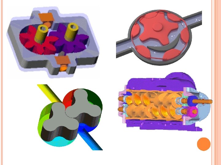
GEAR PUMPS External Gear Pump
WORKING OF EXTERNAL GEAR PUMP The external gear pump is a positive displacement pump composed of a casing with two meshing gears with external teeth. One gear is driven by the shaft coupled to a driver. This gear drives the other gear. The rotation of the gears is such that the liquid comes into the inlet port and flows into and around the outer periphery of the two rotating gears. As the liquid comes around the periphery it is discharged to the outlet port. The flow of the pump is regulated by the size of the cavity (volume) between the teeth and the speed of the gears.
CONTINUED Flow from the outlet is further regulated by the amount of liquid that slips back to the inlet port. The amount of slip depends on the side clearance of the gears to the casing, the peripheral clearance of the gear and bore in the casing, gear-to-gear clearance, developed pressure, and viscosity of the liquid. The lower the viscosity, the greater the slippage. As the viscosity increases, the pump speed is lowered to allow the liquid to fill the space between the rotating teeth.
APPLICATIONS: The most common uses for these pumps are to supply fuel oil for burners, gasoline transfer, kerosene, fuel oil, and diesel oil. They are used for hydraulic devices such as elevators and damper controls. They also pump coolants, paints, bleaches, solvents, syrups, glues, greases, petroleum, and lube oils and are used in general industrial applications. External gear pumps can handle small suspended solids in abrasive applications but will gradually wear and lose performance.
INTERNAL GEAR PUMP
WORKING OF INTERNAL GEAR PUMP The internal gear pump is a rotary flow positive displacement pump design, which is well-suited for a wide range of applications due to its relatively low speed and inlet pressure requirements. These designs have only two moving parts and hence have proven reliable, simple to operate, and easy to maintain. They are often a more efficient alternative than a centrifugal pump, especially as viscosity increases. Internal gear pumps have one gear with internally cut gear teeth that mesh with the other gear that has externally cut gear teeth.
CONTINUED… Pumps of this type are made with a crescentshaped partition. Designs are available to provide the same direction of flow regardless of the direction of shaft rotation. As the gears come out of mesh on the inlet side, liquid is drawn into the pump. The gears have a fairly long time to come out of mesh allowing for favorable filling. The mechanical contacts between the gears form a part of the moving fluid seal between the inlet and outlet ports. The liquid is forced out the discharge port by the meshing of the gears.
APPLICATIONS: Internal gear pumps are applied in petrochemical, marine, terminal unloading, chemical, and general industrial applications for transfer, lubrication, processing, and lowpressure hydraulics handling a wide range of fuel oils, lube oils, and viscous chemicals (both corrosive and noncorrosive).
SCREW PUMP
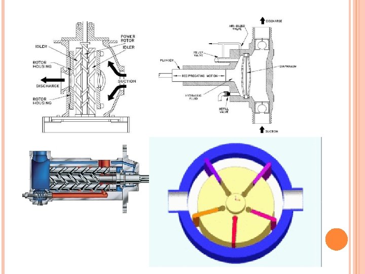
SCREW TYPE PDRP There are many variations in the design of the screw type positive displacement, rotary pump. The primary differences consist of the number of intermeshing screws involved, the pitch of the screws, and the general direction of fluid flow. Two common designs are the two-screw, low-pitch, double-flow pump and the three-screw, high-pitch, double-flow pump. The two-screw, low-pitch, screw pump consists of two screws that mesh with close clearances, mounted on two parallel shafts. One screw has a right-handed thread, and the other screw has a left-handed thread. One shaft is the driving shaft and drives the other shaft through a set of herringbone timing gears. The gears serve to maintain clearances between the screws as they turn and to promote quiet operation. The screws rotate in closely fitting duplex cylinders that have overlapping bores.
CONTINUED All clearances are small, but there is no actual contact between the two screws or between the screws and the cylinder walls. The complete assembly and the usual flow path are shown in Figure. Liquid is trapped at the outer end of each pair of screws. As the first space between the screw threads rotates away from the opposite screw, a one-turn, spiral-shaped quantity of liquid is enclosed when the end of the screw again meshes with the opposite screw. As the screw continues to rotate, the entrapped spiral turns of liquid slide along the cylinder toward the center discharge space while the next slug is being entrapped. The removal of liquid from the suction end by the screws produces a reduction in pressure, which draws liquid through the suction line.
APPLICATIONS: Loading / unloading of fuel oil and other products from: Railway wagon rakes, Truck tankers, Barges, Ships and Tankers. Lubrication, circulation and cooling. Process pumping of high viscous products, bitumen, molasses, soap and similar products. Long distance pipeline pumping of viscous products. Major Industries: Petroleum refineries, Terminals, Depots, Oil blending stations, Thermal power plants, Steel plants, Fertilizer industries, Petrochemical plants, Carbon black, Sugar, Paper and Pulp, Marine.
VANE PUMP
VANE PUMP The simplest vane pump is a circular rotor rotating inside of a larger circular cavity. The centres of these two circles are offset, causing eccentricity. Vanes are allowed to slide into and out of the rotor and seal on all edges, creating vane chambers that do the pumping work. On the intake side of the pump, the vane chambers are increasing in volume. These increasing volume vane chambers are filled with fluid forced in by the inlet pressure. Inlet pressure is actually the pressure from the system being pumped, often just the atmosphere. On the discharge side of the pump, the vane chambers are decreasing in volume, forcing fluid out of the pump. The action of the vane drives out the same volume of fluid with each rotation.
ADVANTAGES AND DISADVANTAGES Advantages Handles thin liquids at relatively higher pressures Compensates for wear through vane extension Sometimes preferred for solvents, LPG Can run dry for short periods Can have one seal or stuffing box Develops good vacuum Disadvantages Can have two stuffing boxes Complex housing and many parts Not suitable for high pressures Not suitable for high viscosity Not good with abrasives
APPLICATIONS Fuel Transfer Auto Industry - Fuels, Lubes, Refrigeration Coolants Bulk Transfer of LPG and NH 3 LPG Cylinder Filling Alcohols Refrigeration - Freons, Ammonia Solvents
THREE LOBE PUMP
WORKING OF LOBE PUMP Lobe pumps are similar to external gear pumps in operation in that fluid flows around the interior of the casing. Unlike external gear pumps, however, the lobes do not make contact. Lobe contact is prevented by external timing gears located in the gearbox. 1. As the lobes come out of mesh, they create expanding volume on the inlet side of the pump. Liquid flows into the cavity and is trapped by the lobes as they rotate. 2. Liquid travels around the interior of the casing in the pockets between the lobes and the casing—it does not pass between the lobes. 3. Finally, the meshing of the lobes forces liquid through the outlet port under pressure.
LOBE PUMP Lobe pumps are frequently used in food applications because they handle solids without damaging the product. Particle size pumped can be much larger in lobe pumps than in other positive displacement types. Since the lobes do not make contact, and clearances are not as close as in other Positive displacement pumps, this design handles low viscosity liquids with diminished performance. Loading characteristics are not as good as other designs, and suction ability is low. High-viscosity liquids require reduced speeds to achieve satisfactory performance. Reductions of 25% of rated speed and lower are common with high-viscosity liquids. Lobe pumps are used in a variety of industries including pulp and paper, chemical, food, beverage, pharmaceutical, and biotechnology. They are popular in these diverse industries because they offer high efficiency, reliability, corrosion resistance.
THE END