GasTurbinePowerplant Prepared by NMG Basic Components Compressor Draws

Gas_Turbine_Power_plant Prepared by: NMG

Basic Components • Compressor – Draws in air & compresses it • Combustion Chamber – Fuel pumped in and ignited to burn with compressed air • Turbine – Hot gases converted to work – Can drive compressor & external load
 to")
Introduction of Gas turbine power plant q Gas turbine: Ø Air is compressed(squeezed) to high pressure by a fan-like device called the compressor. Ø Then fuel and compressed air are mixed in a combustion chamber and ignited. Ø Hot gases are given off, which spin the turbine wheels. Ø Most of the turbine’s power runs the compressor. Part of it drives the generator/machinery. 06 March 2021 3

Gas turbine power plant… q Gas turbine: Description: Ø Gas turbines burn fuels such as oil, nature gas and pulverized (powdered) coal. Ø Instead of using the heat to produce steam, as in steam turbines, gas turbines use the hot gases directly to turn the turbine blades. 06 March 2021 4

Introduction cont…. . q Applications of gas turbine: Ø Gas turbines are used to drive pumps, compressors and high speed cars. Ø Used in aircraft and ships for their propulsion. They are not suitable for automobiles because of their very high speeds. Ø Power generation(used for peak load and as stand-by unit). Note : § Gas turbines run at even higher temperatures than steam turbines, the temperature may be as high as 1100 – 12600 C. § The thermal efficiency of gas turbine made of metal components do not exceed 36%. § Research is underway to use ceramic components at turbine inlet temperature of 13500 C or more, and reach thermal efficiencies over 40% in a 300 k. W unit. 06 March 2021 5

Definition: The gas turbine is an internal combustion engine that uses air as the working fluid. The engine extracts chemical energy from fuel and converts it to mechanical energy using the gaseous energy of the working fluid (air) to drive the engine and propeller, which, in turn, propel the airplane or produce electricity.

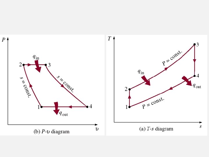
Basic principle 1. Intake of air. 2. Compression of the air (and possibly fu. 3. Combustion, where fuel is injected (if it was not drawn in with the intake air) and burned to convert the stored energy. 4. Expansion and exhaust, where the converted energy is put to use. 1 -2 Isentropic compression (in a compressor) 2 -3 Isobaric (Constant Pressure) heat addition 3 -4 Isentropic expansion (in turbine) 4 -1 Isobaric (Constant Pressure) heat rejection how_combustion_plants_work. swf

Open Cycle Brayton Cycle: Ideal open Cycle for Gas-Turbine Engines Gas turbines usually operate on an open cycle Air at ambient conditions is drawn into the compressor, where its temperature and pressure are raised. The high pressure air proceeds into the combustion chamber, where the fuel is burned at constant pressure. The high-temperature gases then enter the turbine where they expand to atmospheric pressure while producing power output. Some of the output power is used to drive the compressor. The exhaust gases leaving the turbine are thrown out (not re-circulated), causing the cycle to be classified as an open cycle.

Closed Cycle The open gas-turbine cycle can be modelled as a closed cycle, using the air-standard assumptions (Fig. 9– 30). The compression and expansion processes remain the same, but the combustion process is replaced by a constant-pressure heat addition process from an external source. The exhaust process is replaced by a constantpressure heat rejection process to the ambient air. 9

Difference between Open GT and Closed GT Open. Gas. Turbine. swf Closed. Cycle. swf
 For a given output the size of")
Advantages of Closed Cycle Gas Turbine 1) For a given output the size of the compressor and the turbine are very small. 2) There is no corrosion and accumulation of deposits of carbon tar on the blade and nozzles of the turbine. No internal cleaning required. 3) Any fuel of high calorific value may be used, as the products of combustion do not mix with the working fluid. 4) The waste heat of the combustion gases from the heat and reheated can be further used for heating water. This can be used for hot water supply for industrial or domestic purpose. Disadvantages 1) Maintenance 2) Complex system 3) Dependent

Brayton cycle : The Ideal Cycle for Gas Turbine Engines

C. Brayton cycle : The Ideal Cycle for Gas Turbine Engines Thermodynamics analysis Compressor Or work absorb Heat supplied in combustion chamber

C. Brayton cycle : The Ideal Cycle for Gas Turbine Engines Thermodynamics analysis Turbine or expansion work Heat exchanger Heat Reject

Brayton cycle : The Ideal Cycle for Gas Turbine Engines Thermodynamics analysis Thermal efficiency

C. Brayton cycle : The Ideal Cycle for Gas Turbine Engines

Thermodynamics analysis Compressor Turbine wcompressor work wnet wturbine Back work Work ratio Back work ratio rbw = wcomp w turb T 1 T 4 (T 2 - T 1 ) = (T 3 - T 4 )

Difference between Ideal and Actual Gas Turbine Pressure Drop 1. Pressure drop during heat addition and heat rejection process 2. Actual work input to compressor is more 3. Actual work from the turbine is less

Thermodynamics analysis : Turbine efficiency wa actual work h. T = = isentropic work ws h 3 - h 4 ' T 3 - T 4 ' h. T = = h 3 - h 4 T 3 - T 4 T 3 2 2’ 4’ 4 1 s

Thermodynamics analysis : Compressor efficiency T 3 2 2’ 4’ 4 1

Thermodynamics analysis : actual thermal efficiency T 3 2 2’ 4’ 4 1
 Improving")
Means of Improving the Efficiency and the Specific Output of Simple Cycle: A) Improving turbine output. This may be done by ; - • Reheating. The whole expansion in the turbine is achieved in two or more stages and reheating is done after each stage. • Increasing the value of maximum cycle temperature i. e. turbine inlet temperature. This requires. a) Better quality of fuel b) New materials which can withstand high temperatures c) Blade cooling methods. • Improved turbine efficiency. It depends on design improvements. B) Reducing compressor input. This may be done by • Intercooling: Compressor work is reduced by intercooling the air between compressor stages. • By lowering inlet temperature to compressor it is not practical because this will increase the pressure ratio. • By increasing the coprocessor efficiency. This depends upon the design improvement. • Water injection. By injecting water at the inlet to compressor, the work output and efficiency is increased due to the extra mass of water injected and cooling of air. C) Regeneration: This is done by preheating the air with the turbine exhaust, thus saving the fuel consumption

Gas Turbine with Reheater reheat. Cycle. swf

Ideal Cycle Actual cycle Reheat. swf

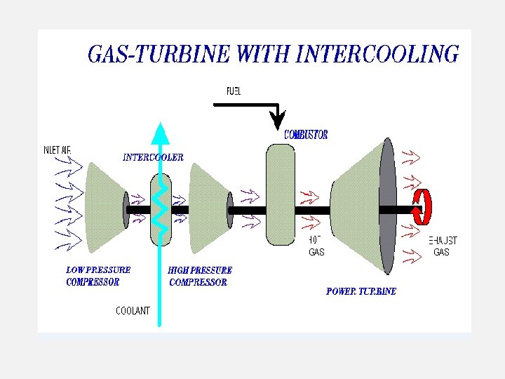
Gas Turbine cycle with intercooler

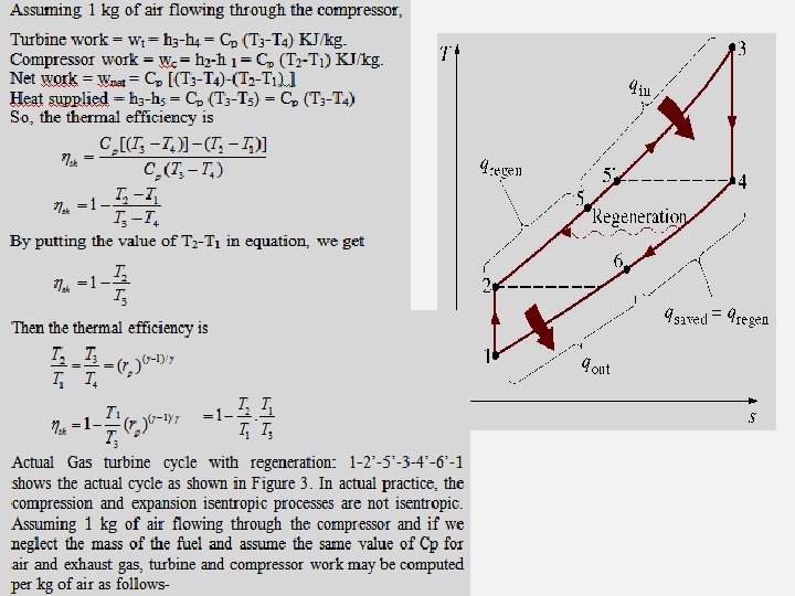
Regeneration is performed by preheating the combustor air with the exhaust gas from the turbine.

• Regeneration – Reduces heat input requirements and lowers heat rejected. Regeneration is performed by preheating the combustor air with the exhaust gas from the turbine.

6 2 1 5 WCOMP QH 3 4 WTURB Regeneration. swf regen. Cycle. swf

Gas Turbine cycle with Intercooler, Regenerator and Reheater reheat. Regen. Multi. Stage. swf Intercooling, reheat & Regeneration. swf

Example A gas turbine power plant operating on an Brayton cycle has a pressure ratio of 8. the gas temperature is 300 K at compressor inlet and 1, 300 K at turbine inlet. Utilizing the air standard assumption, and assuming compressor efficiency of 80% and turbine efficiency is 85%, regenerator having effectiveness of 80% is is install, determine thermal efficiency.

Example The open cycle gas turbine operate on Brayton cycle with pressure ratio 4. 5/1. Air enter the compressor at 210 C and heated to 7800 C at entry to the turbine. If mass flow rate is 140 kg/min, Determine : a) Cycle efficiency b) Power output from the plant. k=1. 4, cp=1. 005 k. J/kg. K Data : rp=4. 5, T 1=294 K, T 3=1053 K, m=2. 33 kg/s

Process 1 -2, isentropic compression Process 3 -4, isentropic expansion Consider 1 kg of heat supply,

Heat rejection Net work output Cycle efficiency

Net work output per second

Example A gas turbine power plant operating on an ideal Brayton cycle has a pressure ratio of 8. The gas temperature is 300 K at compressor inlet and 1, 300 K at turbine inlet. Utilizing the air standard assumption, determine : a) The air and gas temperature at exit of the compressor and turbine, b) the back work ratio, c) The thermal efficiency

Example A gas turbine power plant operating on brayton cycle has a pressure ratio of 8. the gas temperature is 300 K at compressor inlet and 1, 300 K at turbine inlet. Utilizing the air standard assumption, and assuming compressor efficiency of 80% and turbine efficiency is 85%, determine back work ratio, thermal efficiency.

Solution Process 1 -2, isentropic compression on ideal gas T 2 = at compressor exit Process 3 -4, isentropic expansion on ideal gas T 4 = at Turbine exit

Solution Compressor Turbine

Example 9 -2 The ideal air-standard Brayton cycle operates with air entering the compressor at 95 k. Pa, 22 o. C. The pressure ratio rp is 6: 1 and the air leaves the heat addition process at 1100 K. Determine the compressor work and the turbine work per unit mass flow, the cycle efficiency, the back work ratio, and compare the compressor exit temperature to the turbine exit temperature. Assume constant properties. Apply the conservation of energy for steady-flow and neglect changes in kinetic and potential energies to process 1 -2 for the compressor. Note that the compressor is isentropic. The conservation of mass gives 44

For constant specific heats, the compressor work per unit mass flow is Since the compressor is isentropic 45

The conservation of energy for the turbine, process 3 -4, yields for constant specific heats (let’s take a minute for you to get the following result) Since process 3 -4 is isentropic 46

Since P 3 = P 2 and P 4 = P 1, we see that We have already shown the heat supplied to the cycle per unit mass flow in process 2 -3 is 47

The net work done by the cycle is The cycle efficiency becomes 48
- Slides: 48