Sequence Diagrams CECS 343 Mimi Opkins What is


- Slides: 47
Sequence Diagrams CECS 343 Mimi Opkins
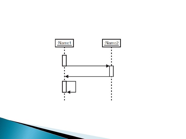
What is a Sequence Diagram �A sequence diagram consists of ◦ Objects represented as named rectangles ◦ Messages represented as solid-line arrow ◦ Time represented as a vertical progression
Objects � Objects are laid out near the top of the diagram from left to right. � They’re arranged in any order that simplifies the diagram. � Extending downward from each object is a dashed line called the object’s lifeline. � Along the lifeline is a narrow rectangle called an activation. � The activation represents an execution of an operation the object carries out. � The length of the rectangle signifies the activation’s duration.
Objects
Messages �A message that goes from one object to another goes from one object’s lifeline to the other object’s lifeline. � An object can also send a message to itself— that is, from its lifeline back to its own lifeline. � UML represents a message as an arrow that starts at one lifeline and ends at another. � The shape of the arrowhead shows what type of message it is.
� Synchronous � Return Message from Call � Asynchronous Message
Time � The diagram represents time in the vertical direction: ◦ Time starts at the top and progresses toward the bottom. ◦ A message that’s closer to the top occurs earlier in time than a message that’s closer to the bottom.
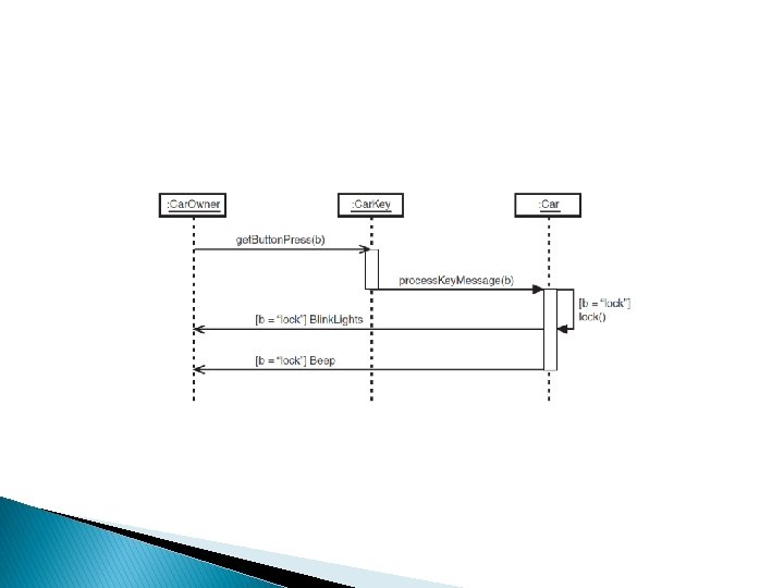
Class Diagram - Cars and Car Keys � Let’s create a class diagram for a keyless entry car: � It allows you to remotely lock and unlock a car. � It also lets you open the car’s trunk. � If you have one of these keys, you know what happens when you push the “lock” button: � The car locks itself, � and then it blinks its lights � and beeps to let you know it’s finished locking its doors.
The Car processes a message from the key and causes the appropriate behavior to take place.
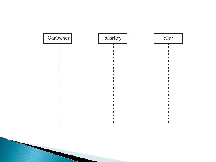
Sequence Diagram � The class diagram is a static view of the little world of the Car. Owner, Car. Key, Car, and the two signals. � A sequence diagram provides a dynamic view. � How? By showing the messages that pass from one of these entities to another. ◦ Start by drawing three objects. 1. One object is an instance of Car. Owner, 2. another is an instance of Car. Key, 3. and the third is an instance of Car. ◦ Lay them out across the top of the diagram and drop a lifeline from each one
Anonymous Objects � As you can see, none of these objects has a specific name (my. Car: Car, for example). These three are anonymous objects. � Next, add the arrows to model messages that go from lifeline to lifeline. ◦ The first message (the one highest in the vertical dimension) is a request from Car. Owner to Car. Key. ◦ The request is for Car. Key to implement its get. Key. Press() operation, registering the button the Car. Owner has pressed (generically referred to as b). ◦ The stick arrowhead indicates that Car. Owner is transferring control to Car. Key.
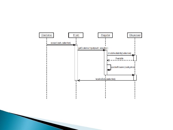
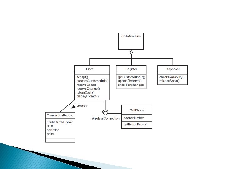
Soda Machine � The sequence diagram is useful for modeling the scenarios of a use case � Assume three components—a front, a register, and a dispenser. � Assume the soda machine is an aggregation of these three components
Soda Machine ◦ Front Accepts selections and cash. ◦ Displays prompts like “Out of selection” and “Use correct change” ◦ Receives change from the register and makes it available to the customer ◦ Returns cash ◦ Receives a can of soda from the dispenser and makes it available to the customer
Soda Machine ◦ Register Gets the customer’s input (that is, the selection and the cash) from the front ◦ Updates its cash reserve ◦ Checks for change ◦ Dispenser Checks the availability of a selection ◦ Releases a can of soda
Class Diagram for Soda Machine
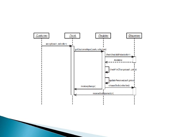
Best-Case Scenario Sequence � The customer inserts the correct change, and the customer’s selection is available: 1. The customer inserts the money into the money slot in the front of the machine and makes a selection. 2. The money travels to the register, which updates itself. 3. Because this is the best-case scenario, an availability check reveals the soda is in stock, and the register has the dispenser release the soda to the front of the machine.
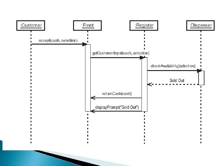
Alternate Scenario � This is just one scenario in this use case. � In another scenario, the customer’s selection might be sold out.
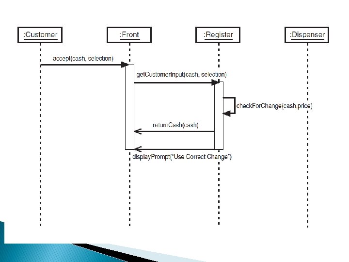
Another Scenario � Here’s another scenario. Suppose the customer does not insert the correct amount of change?
Final Scenario � Finally, suppose the customer does not insert the correct change, and the soda machine is out of change?
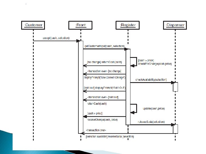
Generic Sequence Diagram � So far, we’ve put just one scenario into a sequence diagram. When you do this, you create an instance sequence diagram. � If you include all of a use case’s scenarios when you draw a sequence diagram, you create a generic sequence diagram.
Generic Sequence Diagram We need some way of indicating conditions; one condition necessitates the messages in one scenario, another condition necessitates others. � Recall from the example with cars and car keys that UML provides the guard condition to indicate if. This is just a bracketed statement for a condition that has to be in place to follow one path rather than another. � For example, to show that an object sends a message only if the selected soda is sold out, preface that message with [sold out]. � The guard conditions provide essentially the same information as the return messages. � For example, [sold out] lets you know that a selection is unavailable, just as the “Sold Out” return message does. For this reason, you can remove the return messages. �
Generic Sequence Diagram � One more idea and you’ll be ready to take the plunge into a generic sequence diagram. � You want to be able to show that if you fully follow one scenario’s sequence of messages to its conclusion, the transaction is over, and that the remaining messages are related to other scenarios. � To do this, you preface the final message in each scenario with «transaction over» .
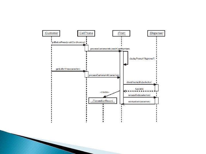
Creating an Object A few years ago, telecommunications giant Ericsson demonstrated a technology that enables customers to use their cell phones to buy from soda machines. � Let’s begin once again with a class diagram. Through a wireless connection, the Cell. Phone interfaces to the Front. � The Front is smarter than before and now has the ability to process information from the Customer. � In this version it acquires an additional capability—the real focus here: It creates a transaction record of the interaction between the customer and the soda machine. � The machine uses this record to charge the customer’s credit card for the soda. Your sequence diagram has to visualize the creation of the transaction record. �
Best Case Scenario � The customer keys his or her credit card information into the cell phone and sends it to the Front. � The Front processes the information and displays an “Approved” prompt to the Customer. � The Customer keys a selection into the cell phone, which sends it to the Front. � In this version of the soda machine, the Front processes the information and communicates directly with the Dispenser to check availability and to instruct the Dispenser to release the soda. � The rest of the scenario is just like the original bestcase scenario in the twentieth-century soda machine, except for the creation of the Transaction. Record
� All the objects are across the top, except the Transaction. Record object. Why? � Because it’s not one of the objects that exists at the beginning of the sequence. � You show its creation by positioning it in the vertical dimension according to when it’s created. � Another aspect of modeling object–creation is the «create» keyword you put on the message sent from the creator object to the created object. � Because the Register isn’t involved in this sequence, it doesn’t appear in the diagram.
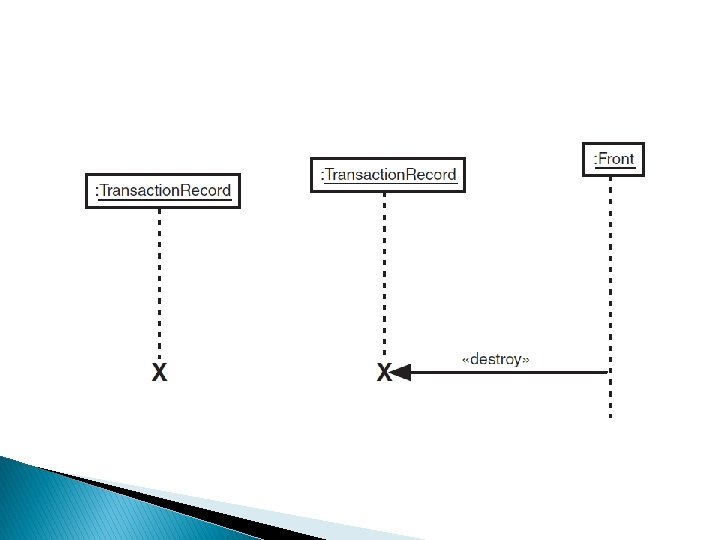
Object Destruction � While we’re on the subject of object creation, we should also talk about object destruction. � To show an object being destroyed, you place a large, bold X at the bottom of its lifeline. � The left-hand part of the figure shows an object destroying itself (perhaps because a certain amount of time has passed). � The right-hand part of the figure shows that an object can instruct another object to destroy itself. � It does this by sending a message whose label is a «destroy» keyword.
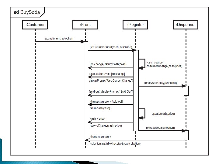
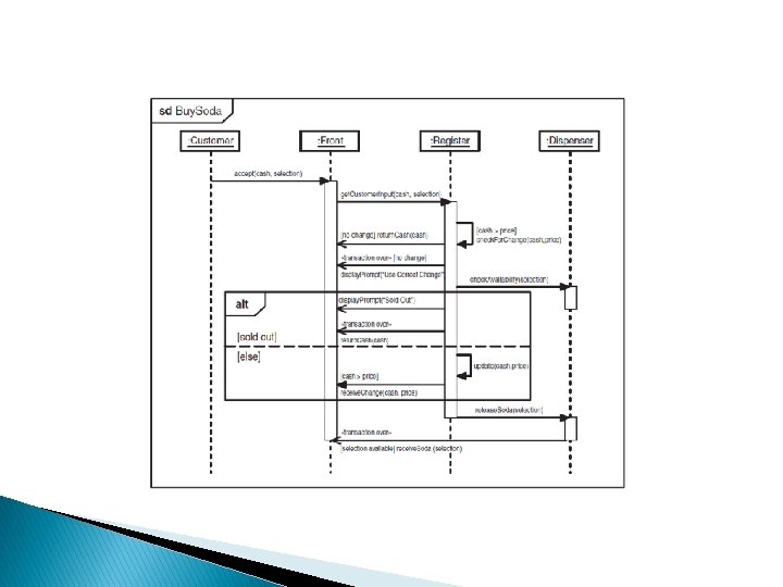
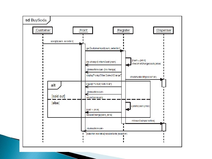
Framing Sequence Diagrams � You can frame a sequence diagram by surrounding it with a border and adding a compartment in the upper left corner. � The compartment contains information that identifies the diagram. � One of the pieces of information is an operator, an expression that describes the type of diagram inside the frame. � For a sequence diagram, the operator is sd. � Along with the operator, the compartment contains the name of the interaction (Buy. Soda) the diagram depicts.
Interaction Occurrences � The framing concept is helpful because you can apply it in a number of ways. � For example: If you’re creating instance sequence diagrams for the scenarios in a use case, you’ll notice a fair amount of duplication from diagram to diagram. � Framing gives you a quick and easy way to reuse part of one sequence diagram in another. � You draw a frame around part of the diagram, label the frame’s compartment, and just insert the frame with a label (but without the messages and lifelines) into the new diagram. � This particular framed part is called an interaction occurrence. Its operator is ref.
The framed part is the interaction occurrence that handles the delivery of the soda
Shows how to reuse that interaction occurrence in the incorrect change scenario.
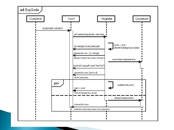
Combined Interaction Fragments An interaction occurrence is a special case of an interaction fragment (generic name for a piece of a sequence diagram). � You can combine these interaction fragments in various ways. � The operator indicates the type of combination. � To show a combination, frame the entire set of fragments, and use a dotted line as a border between adjoining interaction fragments. � The two types of combinations that are the most widely used are denoted by the alt operator and by the par operator. � In the alt combination, each fragment is an alternative and can proceed only under certain conditions. Guard conditions indicate which fragment can take place. �
Combined Interaction Fragments � In contrast with the ref operator, the idea here is clarity rather than reuse. � The guard conditions in the fragments eliminate the need for some of the guard conditions on the messages. � This clarifies the generic diagram and makes it easier to follow. � In the par combination, the combined fragments work in parallel and don’t interfere with one another. � For example, suppose your soda machine works extremely efficiently: It returns the customer’s change and delivers the selection at the same time. � This necessitates that several events happen together.