Liquid Helium Production for Industry 1000000 LYear 40




- Slides: 50
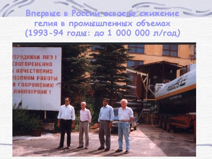
Liquid Helium Production for Industry (1000000 L/Year) 40 m. 3 LHe containers at the moment of the shipment to "Air Products" and "BOC” (1992).
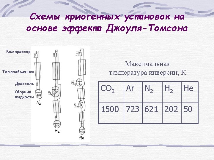
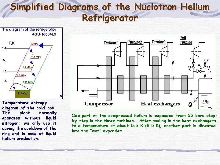
Simplified Diagrams of the Nuclotron Helium Refrigerator Temperature-entropy diagram of the cold box. The plant normally operates without liquid nitrogen; we only use it during the cooldown of the ring and in case of liquid helium production. Compressor Heat exchangers One part of the compressed helium is expanded from 25 bars stepby-step in the three turbines. After cooling in the heat exchangers to a temperature of about 5. 5 K (8. 5 K), another part is directed into the “wet” expander.
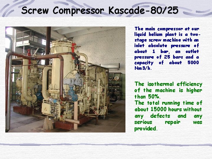
Screw Compressor Kascade-80/25 The main compressor at our liquid helium plant is a twostage screw machine with an inlet absolute pressure of about 1 bar, an outlet pressure of 25 bars and a capacity of about 5000 Nm 3/h. The isothermal efficiency of the machine is higher than 50%. The total running time of about 15000 hours without any defects and any serious repair was provided.
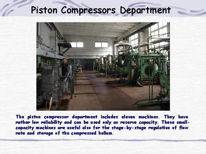
Piston Compressors Department The piston compressor department includes eleven machines. They have rather low reliability and can be used only as reserve capacity. These smallcapacity machines are useful also for the stage-by-stage regulation of flow rate and storage of the compressed helium.
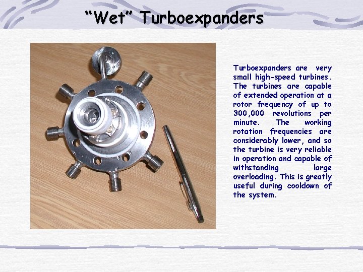
“Wet” Turboexpanders are very small high-speed turbines. The turbines are capable of extended operation at a rotor frequency of up to 300, 000 revolutions per minute. The working rotation frequencies are considerably lower, and so the turbine is very reliable in operation and capable of withstanding large overloading. This is greatly useful during cooldown of the system.
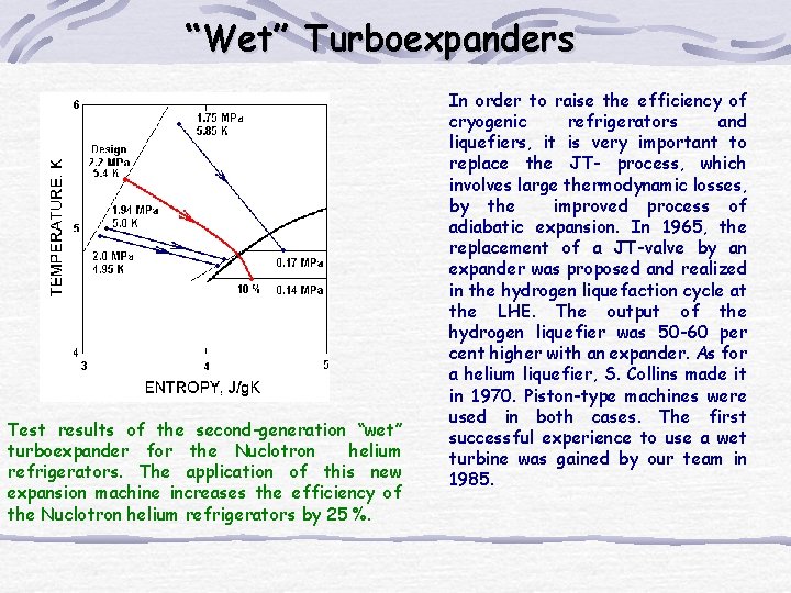
“Wet” Turboexpanders Test results of the second-generation “wet” turboexpander for the Nuclotron helium refrigerators. The application of this new expansion machine increases the efficiency of the Nuclotron helium refrigerators by 25 %. In order to raise the efficiency of cryogenic refrigerators and liquefiers, it is very important to replace the JT- process, which involves large thermodynamic losses, by the improved process of adiabatic expansion. In 1965, the replacement of a JT-valve by an expander was proposed and realized in the hydrogen liquefaction cycle at the LHE. The output of the hydrogen liquefier was 50 -60 per cent higher with an expander. As for a helium liquefier, S. Collins made it in 1970. Piston-type machines were used in both cases. The first successful experience to use a wet turbine was gained by our team in 1985.
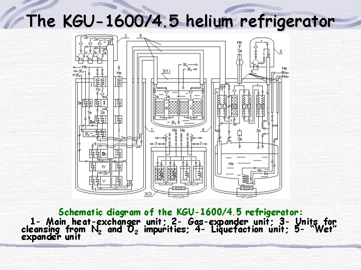
The KGU-1600/4. 5 helium refrigerator Schematic diagram of the KGU-1600/4. 5 refrigerator: 1 - Main heat-exchanger unit; 2 - Gas-expander unit; 3 - Units for cleansing from N 2 and O 2 impurities; 4 - Liquefaction unit; 5 - “Wet” expander unit
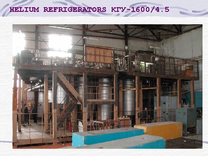
HELIUM REFRIGERATORS КГУ-1600/4. 5
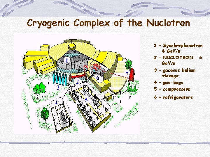
Cryogenic Complex of the Nuclotron 1 – Synchrophasotron 4 Ge. V/n 2 – NUCLOTRON 6 Ge. V/n 3 – gaseous helium storage 4 – gas-bags 5 – compressors 6 – refrigerators
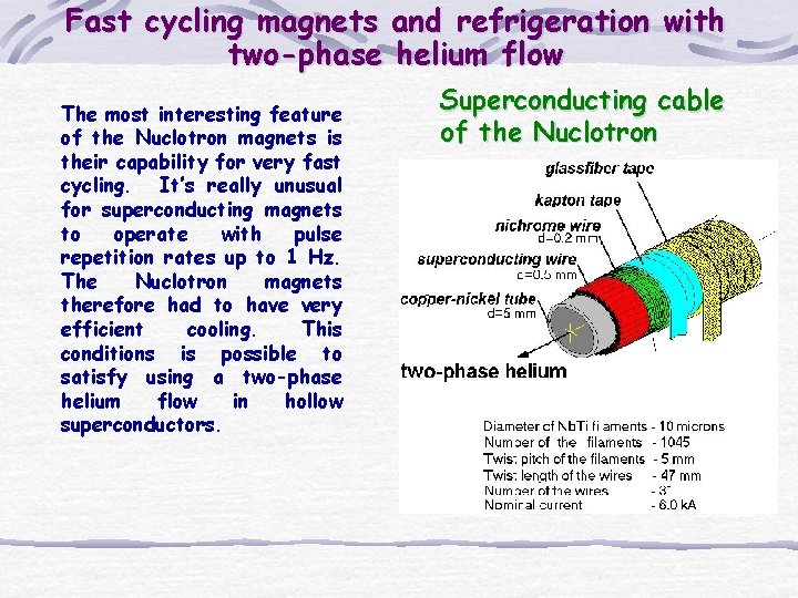
Fast cycling magnets and refrigeration with two-phase helium flow The most interesting feature of the Nuclotron magnets is their capability for very fast cycling. It’s really unusual for superconducting magnets to operate with pulse repetition rates up to 1 Hz. The Nuclotron magnets therefore had to have very efficient cooling. This conditions is possible to satisfy using a two-phase helium flow in hollow superconductors. Superconducting cable of the Nuclotron
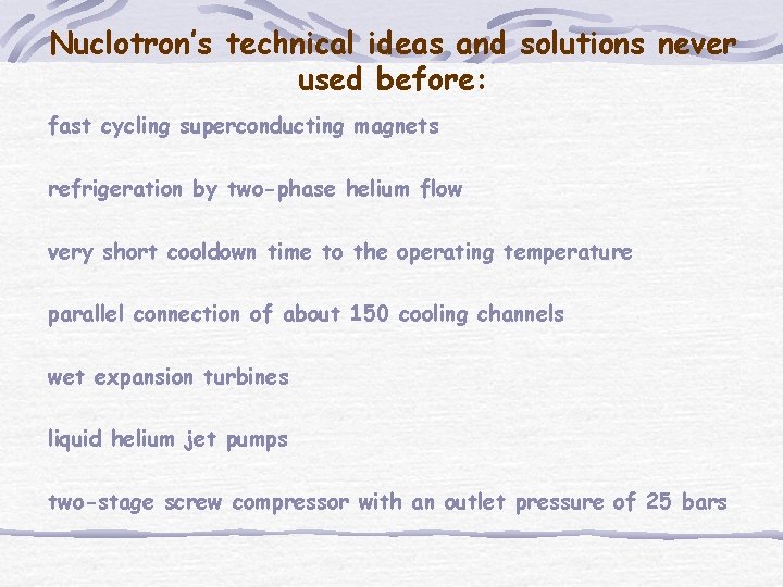
Nuclotron’s technical ideas and solutions never used before: fast cycling superconducting magnets refrigeration by two-phase helium flow very short cooldown time to the operating temperature parallel connection of about 150 cooling channels wet expansion turbines liquid helium jet pumps two-stage screw compressor with an outlet pressure of 25 bars
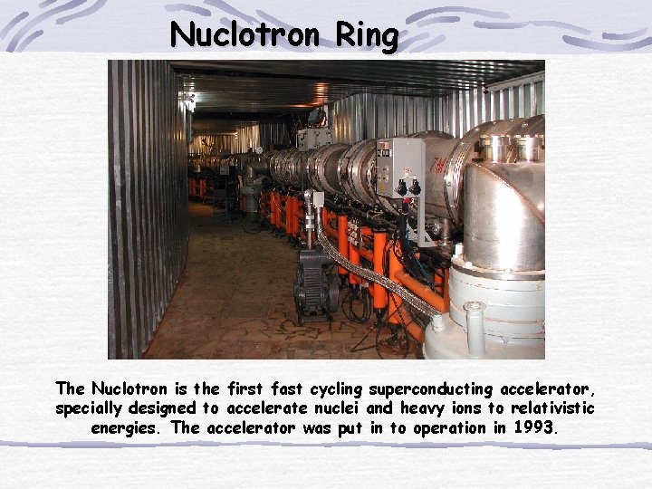
Nuclotron Ring The Nuclotron is the first fast cycling superconducting accelerator, specially designed to accelerate nuclei and heavy ions to relativistic energies. The accelerator was put in to operation in 1993.
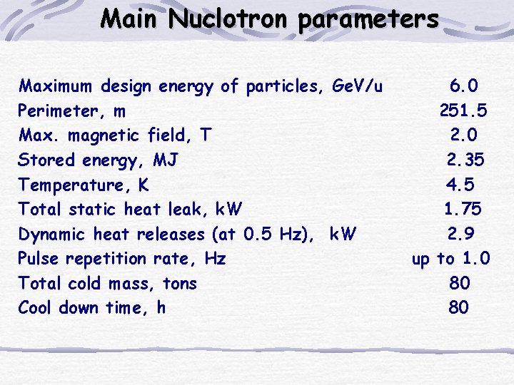
Main Nuclotron parameters Maximum design energy of particles, Ge. V/u Perimeter, m Max. magnetic field, T Stored energy, MJ Temperature, K Total static heat leak, k. W Dynamic heat releases (at 0. 5 Hz), k. W Pulse repetition rate, Hz Total cold mass, tons Cool down time, h 6. 0 251. 5 2. 0 2. 35 4. 5 1. 75 2. 9 up to 1. 0 80 80
The Nuclotron Ring Basic elements of the ring are: 96 superconducting dipole magnets, 64 quadrupole magnets, 28 multipole correctors with three or four types of winding in each. Supply current to the main magnets and energy evacuation as well are provided by twelve 6 k. A current leads, cooled by cold helium vapor. MAIN CHARACTERISTICS OF THE MAGNETS
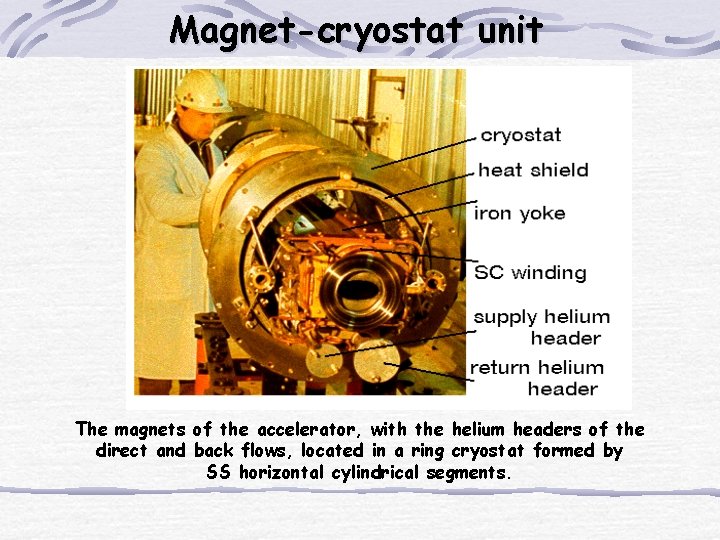
Magnet-cryostat unit The magnets of the accelerator, with the helium headers of the direct and back flows, located in a ring cryostat formed by SS horizontal cylindrical segments.
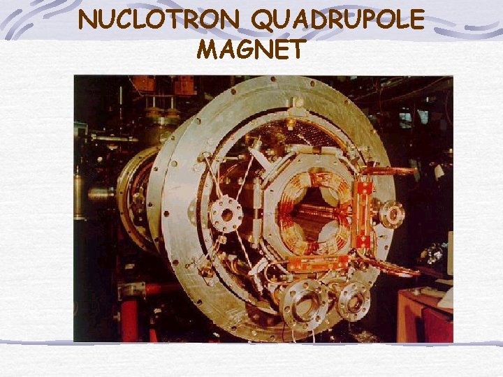
NUCLOTRON QUADRUPOLE MAGNET
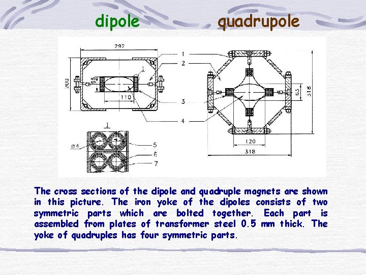
dipole quadrupole The cross sections of the dipole and quadruple magnets are shown in this picture. The iron yoke of the dipoles consists of two symmetric parts which are bolted together. Each part is assembled from plates of transformer steel 0. 5 mm thick. The yoke of quadruples has four symmetric parts.
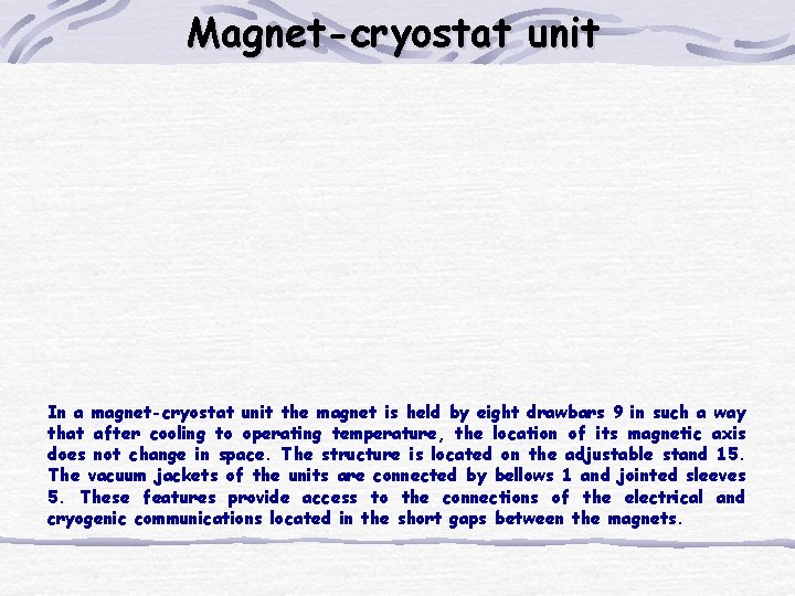
Magnet-cryostat unit In a magnet-cryostat unit the magnet is held by eight drawbars 9 in such a way that after cooling to operating temperature, the location of its magnetic axis does not change in space. The structure is located on the adjustable stand 15. The vacuum jackets of the units are connected by bellows 1 and jointed sleeves 5. These features provide access to the connections of the electrical and cryogenic communications located in the short gaps between the magnets.
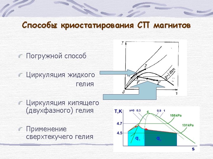
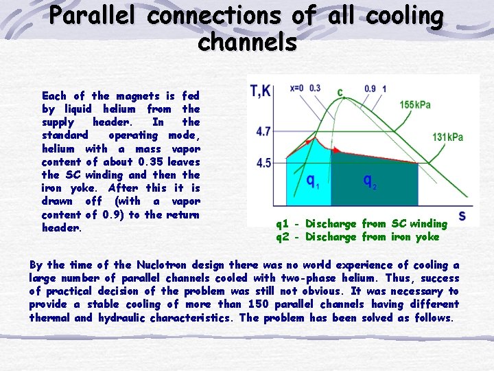
Parallel connections of all cooling channels Each of the magnets is fed by liquid helium from the supply header. In the standard operating mode, helium with a mass vapor content of about 0. 35 leaves the SC winding and then the iron yoke. After this it is drawn off (with a vapor content of 0. 9) to the return header. q 1 - Discharge from SC winding q 2 - Discharge from iron yoke By the time of the Nuclotron design there was no world experience of cooling a large number of parallel channels cooled with two-phase helium. Thus, success of practical decision of the problem was still not obvious. It was necessary to provide a stable cooling of more than 150 parallel channels having different thermal and hydraulic characteristics. The problem has been solved as follows.
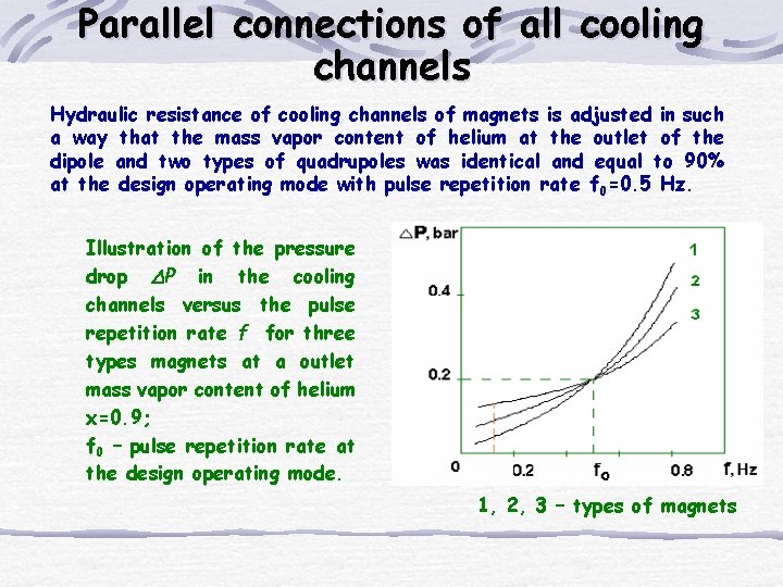
Parallel connections of all cooling channels Hydraulic resistance of cooling channels of magnets is adjusted in such a way that the mass vapor content of helium at the outlet of the dipole and two types of quadrupoles was identical and equal to 90% at the design operating mode with pulse repetition rate f 0=0. 5 Hz. Illustration of the pressure drop P in the cooling channels versus the pulse repetition rate f for three types magnets at a outlet mass vapor content of helium x=0. 9; f 0 – pulse repetition rate at the design operating mode. 1, 2, 3 – types of magnets
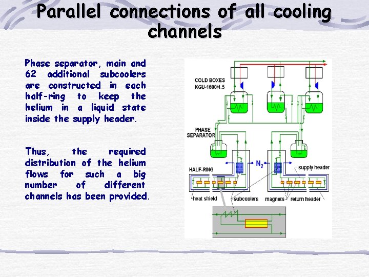
Parallel connections of all cooling channels Phase separator, main and 62 additional subcoolers are constructed in each half-ring to keep the helium in a liquid state inside the supply header. Thus, the required distribution of the helium flows for such a big number of different channels has been provided.
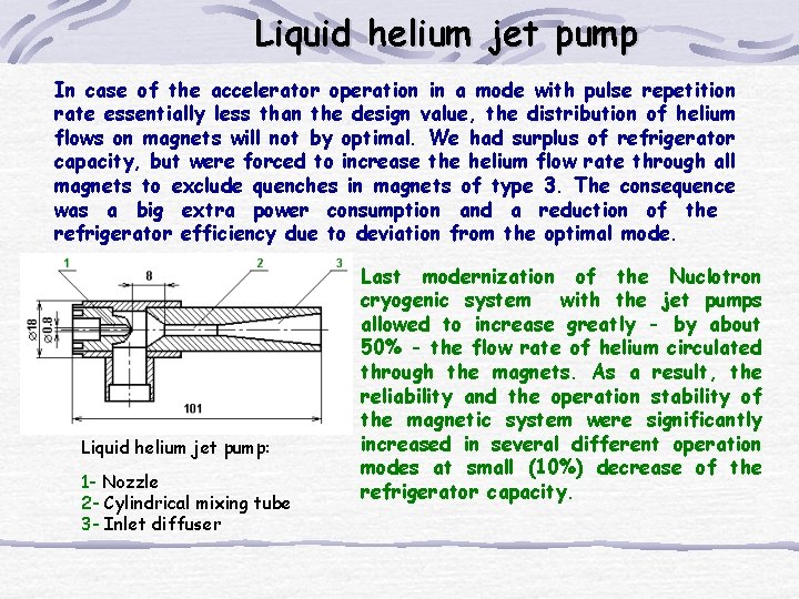
Liquid helium jet pump In case of the accelerator operation in a mode with pulse repetition rate essentially less than the design value, the distribution of helium flows on magnets will not by optimal. We had surplus of refrigerator capacity, but were forced to increase the helium flow rate through all magnets to exclude quenches in magnets of type 3. The consequence was a big extra power consumption and a reduction of the refrigerator efficiency due to deviation from the optimal mode. Liquid helium jet pump: 1 - Nozzle 2 - Cylindrical mixing tube 3 - Inlet diffuser Last modernization of the Nuclotron cryogenic system with the jet pumps allowed to increase greatly - by about 50% - the flow rate of helium circulated through the magnets. As a result, the reliability and the operation stability of the magnetic system were significantly increased in several different operation modes at small (10%) decrease of the refrigerator capacity.
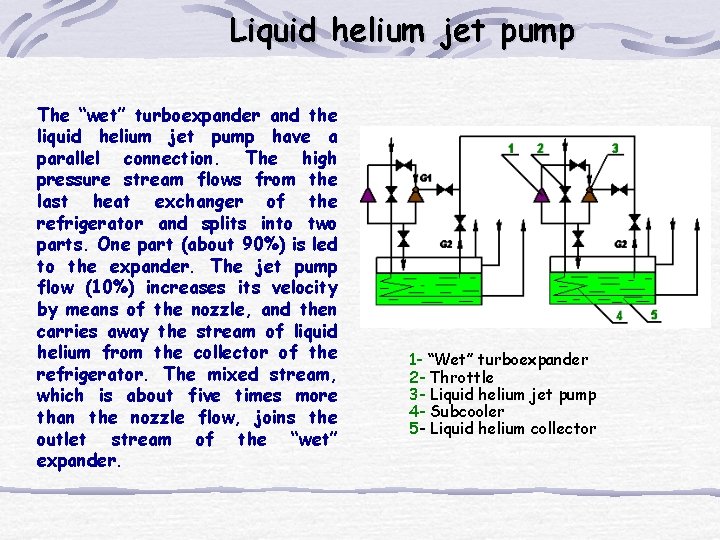
Liquid helium jet pump The “wet” turboexpander and the liquid helium jet pump have a parallel connection. The high pressure stream flows from the last heat exchanger of the refrigerator and splits into two parts. One part (about 90%) is led to the expander. The jet pump flow (10%) increases its velocity by means of the nozzle, and then carries away the stream of liquid helium from the collector of the refrigerator. The mixed stream, which is about five times more than the nozzle flow, joins the outlet stream of the “wet” expander. 1 - “Wet” turboexpander 2 - Throttle 3 - Liquid helium jet pump 4 - Subcooler 5 - Liquid helium collector
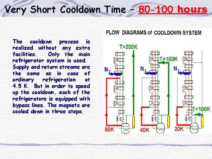
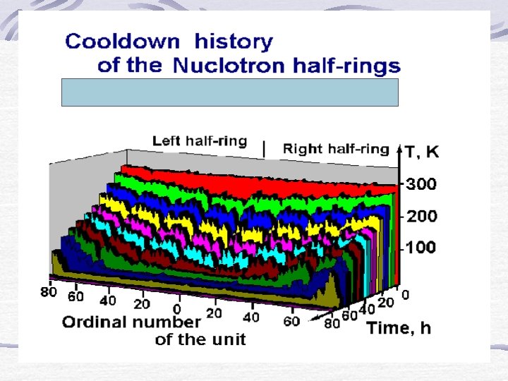
Very Short Cooldown Time – 80 -100 hours The cooldown process is realized without any extra facilities. Only the main refrigerator system is used. Supply and return streams are the same as in case of ordinary refrigeration at 4. 5 K. But in order to speed up the cooldown, each of the refrigerators is equipped with bypass lines. The magnets are cooled down in three steps.
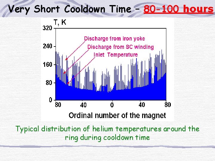
Very Short Cooldown Time – 80 -100 hours Typical distribution of helium temperatures around the ring during cooldown time