Lecture 4 Application of Xray diffraction XRD technique
 technique on the characterization of in nano")


 • The first kind")


")
")

 – Taramalı Elektron Mikroskopu (SEM) –")
- Slides: 36
Lecture 4 Application of X-ray diffraction (XRD) technique on the characterization of in nano materials
History of X-ray and XRD • Wilhelm Conrad Röntgen discovered X-Rays in 1895. • 1901 Nobel prize in Physics Wilhelm Conrad Röntgen (1845 -1923) Bertha Röntgen’s Hand 8 Nov, 1895 A modern radiograph of a hand
History of X-ray and XRD • • • Radiographs like the ones in the last slide are simply shadowgrams. The X-rays either pass straight through or are stopped by the object. The diagram on the upper left illustrates the principle and shows a perfect shadow. In reality, a large fraction of the X -rays are not simply absorbed or transmitted by the object but are scattered. The diagram on the bottom left illustrates this effect and illustrates the fuzzy edge of the object that is produced in the image by the scattered X-rays.
Schematic for X-ray Diffraction • A continuous beam of X-rays is incident on the crystal • The diffracted radiation is very intense in certain directions – These directions correspond to constructive interference from waves reflected from the layers of the crystal • The diffraction pattern is detected by photographic film
History of X-ray and XRD Max von Laue (1897 -1960) • The first kind of scatter process to be recognised was discovered by Max von Laue who was awarded the Nobel prize for physics in 1914 "for his discovery of the diffraction of X-rays by crystals". His collaborators Walter Friedrich and Paul Knipping took the picture on the bottom left in 1912. It shows how a beam of X-rays is scattered into a characteristic pattern by a crystal. In this case it is copper sulphate. • The X-ray diffraction pattern of a pure substance is like a fingerprint of the substance. The powder diffraction method is thus ideally suited for characterization and identification of polycrystalline phases.
Production of X-rays • X-rays are produced when highspeed electrons are suddenly slowed down – Can be caused by the electron striking a metal target • A current in the filament causes electrons to be emitted • These freed electrons are accelerated toward a dense metal target • The target is held at a higher potential than the filament
Equipment Bruker D 8 Analytical X-ray Systems
Goniometer 2 -Theta: Theta Setup
X-ray spectrum
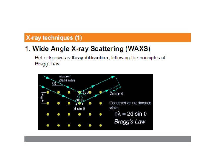
Bragg’s Law • The beam reflected from the lower surface travels farther than the one reflected from the upper surface • If the path difference equals some integral multiple of the wavelength, constructive interference occurs • Bragg’s Law gives the conditions for constructive interference 2 d sin θ = m λ, m = 1, 2, 3…
Problem: X-ray diffraction X-rays of wavelength 0. 140 nm are reflected from a certain crystal, and the first-order maximum occurs at an angle of 14. 4°. What value does this give for the interplanar spacing of this crystal?
Photo of X-ray Diffraction Pattern • The array of spots is called a Laue pattern • The crystal structure is determined by analyzing the positions and intensities of the various spots • This is for Na. Cl
Nano-Kompozitler
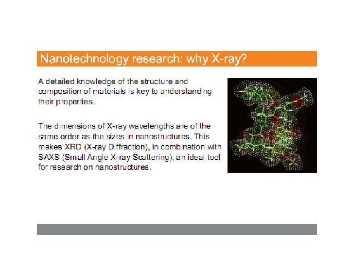
Nano-Kompozitler • Nanoteknolojinin özü, moleküler boyutta çalışarak, moleküler yapısı yenilenmiş büyük yapılar elde etmektir. Malzemelerin nanometrik boyuttaki özellikleri, aynı malzemenin makro boyuttaki özelliklerine göre değişiklik göstermektedir. Nano kompozitler, bir matris içerisinde nanometre büyüklüğünde parçacıkların dağılması ile oluşan malzemelerdir. • Nano kompozitlerin malzemeye getirdiği üstünlükler; modülü arttırması, güçlendirmesi, ısı direncini arttırması, malzemeye gaz sızmasını engellemesi, yanıcılığını azaltması olarak sıralanabilir.
NANO-KOMPOZİTLER metal / seramik metal / metal Nano Kompozitler seramik / seramik polimer / seramik inorganik/ polimer
NANO-KOMPOZİTLER 1. Nanokompozitler seramik/seramik 2. Al 2 O 3/(Si. C, Si 3 N 4, Ti. C, Ti. N, Ti. B 2, BN), Mg. O/Si. C, Si 3 N 4/(Si. C, Ti. N, BN), Sialon/Si. C, B 4 C/Si. C/Ti. B 2 2. Nanokompozitler seramik/metal 1. 3. Al 2 O 3/(W, Mo, Ti, Ni, Co, Fe. Ni), Zr. O 2/(Mo, Ni. Co) 2. Mg. O/(Fe, Ni) 3. Nanokompozit temelli fonksiyonel seramikler 4. Ba. Ti. O 3, Zn. O, c-Zr. O 2 based nanocomposites 5. 4. Nanokompozitler metal/seramic 6. Ti-Al Intermetalic based nanocomposites, Mo. Si 2 based nanocomposites 7. 5. Nanokompozitler polimer/seramik ve polimer/metal
Toz Mikroyapı Makroyapı Arzu edilen özelliklere Sahip KOMPOZİT MALZEME Mukavemet, tokluk, sürünme, kimyasal kararlılık, Yüksek sıcaklık özellikleri
NANO-KOMPOZİTLER • Nanoboyuttaki tozlar, gelişmiş özelliklere sahip nanokompozitleri oluşturmak üzere seramik, metal ya da polimer gibi malzemeler içinde destekleyici olarak kullanılmaktadır. • • Nano toz / Nano toz seramik kompozitler için kullanılacak tozlar; Yüksek kimyasal saflık Homojen toz boyut dağılımı Düşük topaklaşma Nano boyutta homojen olarak dağılmış tozların elde edilmesi gerekir. • BU NEDENLE TOZ ÜRETİM YÖNTEMİ ÖNEMLİ BİR BASAMAKTIR.
DOLGU MADDELERİ
KİL • • Yüksek iyon değişim kapasitesi Yüksek yüzey alanı/hacim oranı, Kolay işlenebilirlik, Düşük maliyet Polimerlerin termal, mekanik ve yanmazlık özelliklerini, kilin yapı içinde kolay dağılımı ve kil tabakalarının birbirinden ayrılmasıyla geliştirir.
MONTMORİLLONİT (MMT)
MONTMORİLLONİT (MMT)
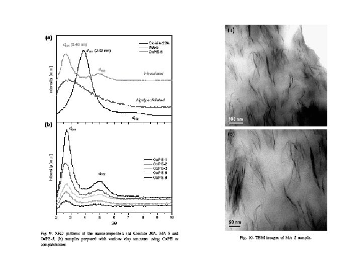
3 tip yapı oluşmaktadır: 1. Mikro kompozit; Polimer kil tabakası arasına giremez. Killer yığın halinde bulunur. m nm 2. Intercalated nanokompozit; Polimer zincirleri kil tabakaları arasına yerleşmiştir. nm 3. Exfoliated nanokompozit; Kil tabakaları birbirinden tamamen ayrılmış ve polimer matriksine dağılmıştır. Polimer/nanokil etkileşimi maksimumdur.
Nanokompozit Karakterizasyon Yöntemleri – X Işını Kırınımı (XRD) – Taramalı Elektron Mikroskopu (SEM) – Geçirimli Elektron Mikroskopu (TEM) – Taramalı Sonda Mikroskobu (SPM) – Yakın Alan Taramalı Optik Mikroskop