LAN Redundancy STP Introduction Network redundancy is a


 attribute,")


 Bridge Protocol Data Units (BPDUs) are frames that contain")
 to determine which")


 Rapid Spanning Tree Protocol (RSTP) enables STP Root Ports and")


 is a Cisco Systems proprietary networking protocol, which is")

# interface range fasttethernet")


 - A Cisco-proprietary FHRP designed")
 VRRP is a computer networking protocol that provides")
 Cisco-proprietary FHRP that protects data traffic from a failed")


- Slides: 48
LAN Redundancy STP
Introduction Network redundancy is a key to maintaining network reliability. Multiple physical links between devices provide redundant paths. The network can then continue to operate when a single link or port has failed. Redundant links can also share the traffic load and increase capacity
Multiple paths need to be managed so that Layer 2 loops are not created. The best paths are chosen, and an alternate path is immediately available should a primary path fail. The Spanning Tree Protocols are used to manage Layer 2 redundancy.
Terms Broadcast Storm A broadcast storm occurs when a network system is overwhelmed by continuous multicast or broadcast traffic. When different nodes are sending/broadcasting data over a network link, and the other network devices are rebroadcasting the data back to the network link in response, this eventually causes the whole network to melt down. Switching loop A Switching loop or bridge loop occurs in computer networks when there is more than one Layer 2 (OSI model) path between two endpoints (e. g. multiple connections between two network switches or two ports on the same switch connected to each other
MAC Database Instability Ethernet frames do not have a time to live (TTL) attribute, like IP packets. As a result, if there is no mechanism enabled to block continued propagation of these frames on a switched network, they continue to propagate between switches endlessly, or until a link is disrupted and breaks the loop. This continued propagation between switches can result in MAC database instability. This can occur due to broadcast frames forwarding.
Redundant Hierarchical Topology
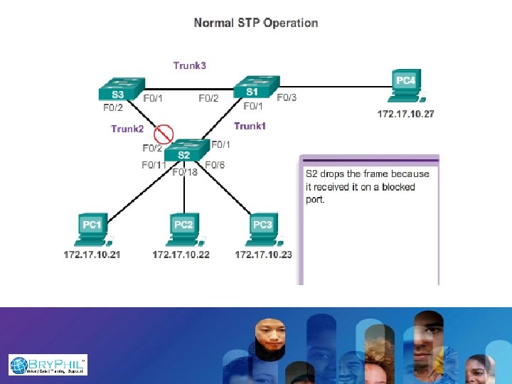
Loops and duplicate frames have severe consequences for a switched network. The Spanning Tree Protocol (STP) was developed to address these issues. STP ensures that there is only one logical path between all destinations on the network by intentionally blocking redundant paths that could cause a loop. A port is considered blocked when user data is prevented from entering or leaving that port.
Bridge Protocol Data Unit (BPDU) Bridge Protocol Data Units (BPDUs) are frames that contain information about the Spanning tree protocol (STP). Switches send BPDUs using a unique MAC address from its origin port and a multicast address as destination. . For STP algorithms to function, the switches need to share information about themselves and their connections. What they share bridge protocol data units (BPDUs)
IEEE 802. 1 D STP uses the Spanning Tree Algorithm (STA) to determine which switch ports on a network must be put in blocking state to prevent loops from occurring. The STA designates a single switch as the root bridge and uses it as the reference point for all path calculations.
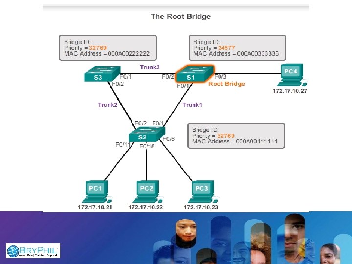
A BPDU is a messaging frame exchanged by switches for STP. Each BPDU contains a BID that identifies the switch that sent the BPDU. The BID contains a priority value, the MAC address of the sending switch, and an optional extended system ID. The lowest BID value is determined by the combination of these three fields.
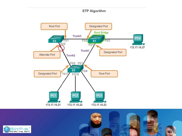
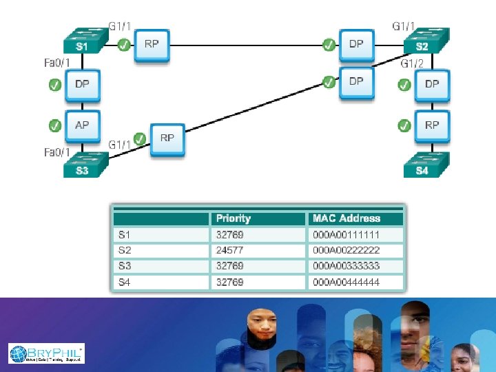
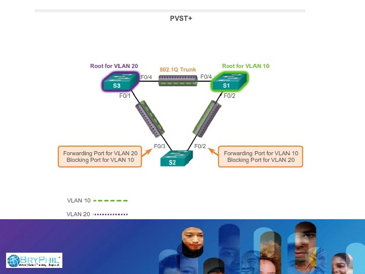
Root ports - Switch ports closest to the root bridge. In the figure, the root port on S 2 is F 0/1 configured for the trunk link between S 2 and S 1. The root port on S 3 is F 0/1, configured for the trunk link between S 3 and S 1. Root ports are selected on a perswitch basis. Designated ports - All non-root ports that are still permitted to forward traffic on the network. In the figure, switch ports (F 0/1 and F 0/2) on S 1 are designated ports. S 2 also has its port F 0/2 configured as a designated port. Designated ports are selected on a per-trunk basis. If one end of a trunk is a root port, then the other end is a designated port. All ports on the root bridge are designated ports. Alternate and backup ports - Alternate ports and backup ports are configured to be in a blocking state to prevent loops. In the figure, the STA configured port F 0/2 on S 3 in the alternate role. Port F 0/2 on S 3 is in the blocking state. Alternate ports are selected only on trunk links where neither end is a root port. Notice in the figure that only one end of the trunk is blocked. This allows for faster transition to a forwarding state, when necessary. (Blocking ports only come into play when two ports on the same switch are connected to each other via a hub or single cable. ) Disabled ports - A disabled port is a switch port that is shut down.
Switch Election Process All switches in the broadcast domain participate in the election process. After a switch boots, it begins to send out BPDU frames every two seconds. These BPDUs contain the switch BID and the root ID. As the switches forward their BPDU frames, adjacent switches in the broadcast domain read the root ID information from the BPDU frames. If the root ID from a BPDU received is lower than the root ID on the receiving switch, then the receiving switch updates its root ID, identifying the adjacent switch as the root bridge. Actually, it may not be an adjacent switch, but could be any other switch in the broadcast domain. The switch then forwards new BPDU frames with the lower root ID to the other adjacent switches. Eventually, the switch with the lowest BID ends up being identified as the root bridge for the spanning tree instance. There is a root bridge elected for each spanning tree instance. It is possible to have multiple distinct root bridges. If all ports on all switches are members of VLAN 1, then there is only one spanning tree instance. The extended system ID plays a role in how spanning tree instances are determined.
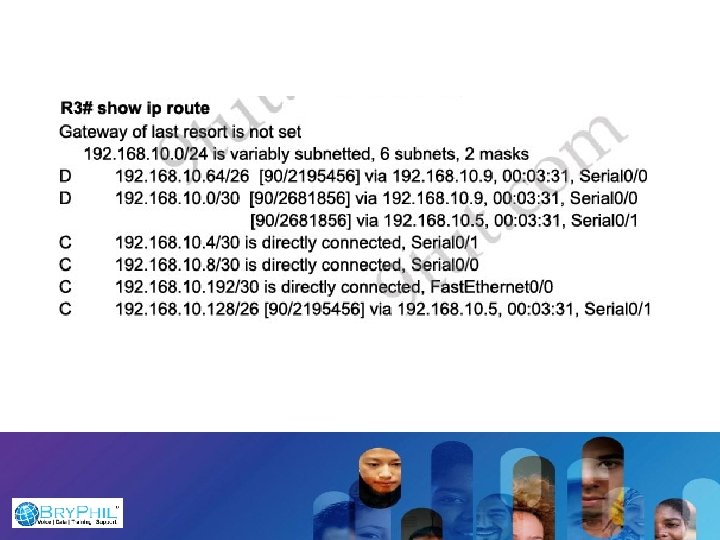
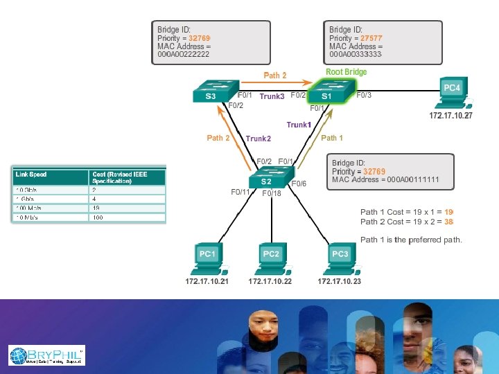
Path cost calculation after root bridge is elected When the root bridge has been elected for the spanning tree instance, the STA starts the process of determining the best paths to the root bridge from all destinations in the broadcast domain. The path information is determined by summing up the individual port costs along the path from the destination to the root bridge. Each “destination” is actually a switch port.
Manual Port Cost Configuration To configure the port cost of an interface enter the spanning-tree cost value command in interface configuration mode. The value can be between 1 and 200, 000.
The Root ID field indicates the root bridge by listing its 2 -byte priority followed by its 6 byte MAC address ID. When a switch first boots, the root ID is the same as the bridge ID. However, as the election process occurs, the lowest bridge ID replaces the local root ID to identify the root bridge switch.
Bridge Priority The bridge priority is a customizable value that can be used to influence which switch becomes the root bridge. The switch with the lowest priority, which implies the lowest BID, becomes the root bridge because a lower priority value takes precedence. Note that the default priority is 32768. But you will always fine the default + VLAN ID
Test your Understanding
Lab - Building a Switched Network with Redundant Links
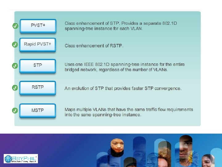
Varieties of Spanning Tree Protocols
Characteristics of Spanning Tree Protocol
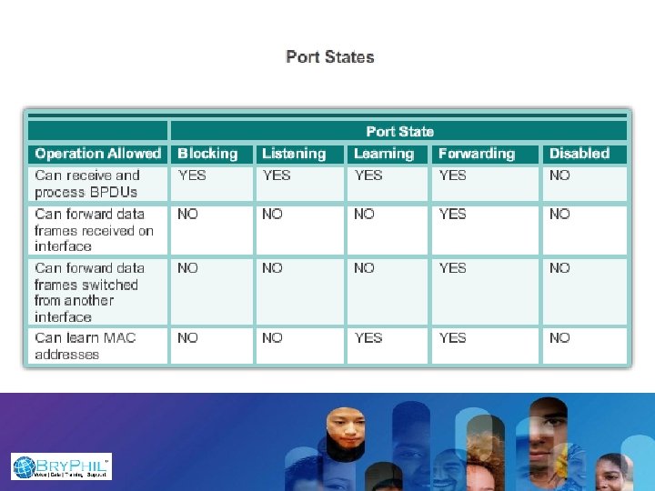
Blocking - The port is an alternate port and does not participate in frame forwarding. The port receives BPDU frames to determine the location and root ID of the root bridge switch and what port roles each switch port should assume in the final active STP topology. Listening - Listens for the path to the root. STP has determined that the port can participate in frame forwarding according to the BPDU frames that the switch has received thus far. At this point, the switch port not only receives BPDU frames, it also transmits own BPDU frames and inform adjacent switches that the switch port is preparing to participate in the active topology. Learning - Learns the MAC addresses. The port prepares to participate in frame forwarding and begins to populate the MAC address table. Forwarding - The port is considered part of the active topology. It forwards data frames and sends and receives BPDU frames. Disabled - The Layer 2 port does not participate in spanning tree and does not forward frames. The disabled state is set when the switch port is administratively disabled. Note that the number of ports in each of the various states (blocking, listening, learning, or forwarding) can be displayed with the show spanning-tree summary command.
Note that the number of ports in each of the various states (blocking, listening, learning, or forwarding) can be displayed with the show spanning-tree summary command. For each VLAN in a switched network, PVST+ performs four steps to provide a loop-free logical network topology: 1. Elects one root bridge - Only one switch can act as the root bridge (for a given VLAN). The root bridge is the switch with the lowest bridge ID. On the root bridge, all ports are designated ports (in particular, no root ports). 2. Selects the root port on each non-root bridge - STP establishes one root port on each non-root bridge. The root port is the lowest-cost path from the non-root bridge to the root bridge, indicating the direction of the best path to the root bridge. Root ports are normally in the forwarding state. 3. Selects the designated port on each segment - On each link, STP establishes one designated port. The designated port is selected on the switch that has the lowest-cost path to the root bridge. Designated ports are normally in the forwarding state, forwarding traffic for the segment. 4. The remaining ports in the switched network are alternate ports - Alternate ports normally remain in the blocking state, to logically break the loop topology. When a port is in the blocking state, it does not forward traffic, but can still process received BPDU messages.
Rapid Spanning Tree Protocol(RSTP) Rapid Spanning Tree Protocol (RSTP) enables STP Root Ports and STP Designated Ports to change from the blocking to forwarding port state in a few seconds.
“spanning-tree portfast” Will convert STP to RSTP
Etherchannel - Reduces port cost - Determines packet flow
Port Aggregation Protocol (PAg. P) is a Cisco Systems proprietary networking protocol, which is used for the automated, logical aggregation of Ethernet switch ports, known as an etherchannel.
Ether. Channel Modes Mode Protocol Auto PAg. P Desirable PAg. P On Ether. Channel Active LACP Passive LACP Description Sets the interface to respond to PAg. P negotiation packets, but the interface will start negotiations on its own. Sets the interface to actively attempt to negotiate a PAg. P connection. Forces the connection to bring all links up without using a protocol to negotiate connections. This mode can only connect to another device that is also set to on. When using this mode, the switch does not negotiate the link using either PAg. P or LACP. Sets the interface to actively attempt to negotiate connections with other LACP devices. Sets the interface to respond to LACP data if it receives negotiation requests from other systems.
Configuring Etherchannels Switch 1> enable Switch 1# configure terminal Switch 1(config)# interface range fasttethernet 0/11 -12 Switch 1(config-if-range)# switchport mode access Switch 1(config-if-range)# switchport access vlan _ID Switch 1(config-if-range)# channel-group 5 mode desirable Switch 1(config-if-range)# end
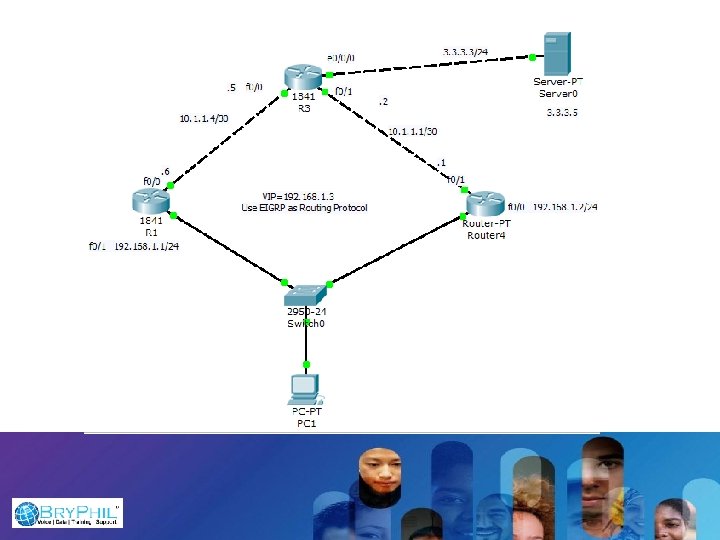
First Hop Redundant Protocol HSRP
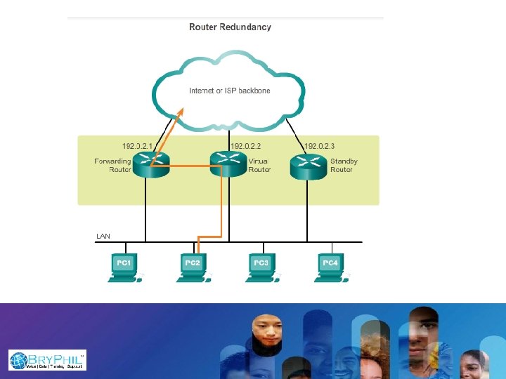
The IP address of the virtual router is configured as the default gateway for the workstations on a specific IP segment. When frames are sent from host devices to the default gateway, the hosts use ARP to resolve the MAC address that is associated with the IP address of the default gateway. The ARP resolution returns the MAC address of the virtual router. Frames that are sent to the MAC address of the virtual router can then be physically processed by the currently active router within the virtual router group
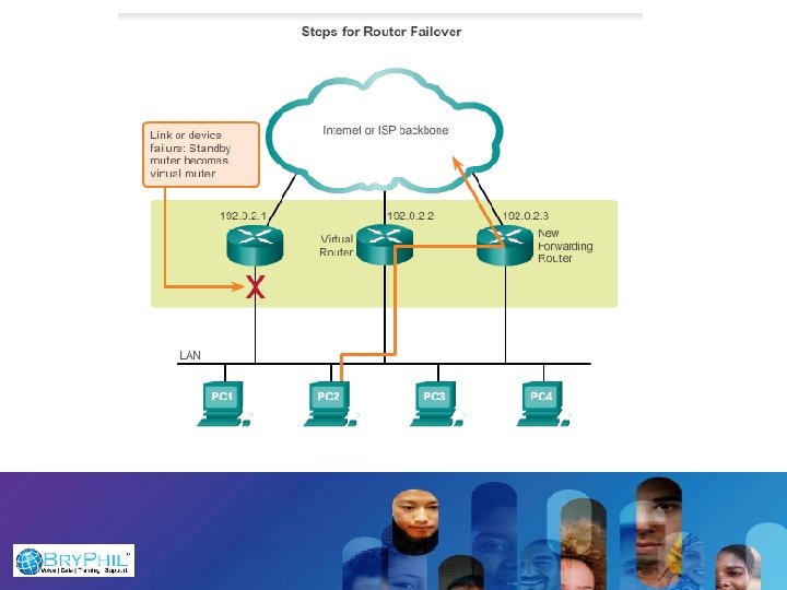
First Hop Redundancy Protocols Hot Standby Router Protocol (HSRP) - A Cisco-proprietary FHRP designed to allow for transparent failover of a first-hop IPv 4 device. HSRP provides high network availability by providing first-hop routing redundancy for IPv 4 hosts on networks configured with an IPv 4 default gateway address. HSRP is used in a group of routers for selecting an active device and a standby device (Proprietary) Active vs Standby
The Virtual Router Redundancy Protocol (VRRP) VRRP is a computer networking protocol that provides for automatic assignment of available Internet Protocol (IP) routers to participating hosts. This increases the availability and reliability of routing paths via automatic default gateway selections on an IP subnetwork. (non Proprietary) Master vs Backup
Gateway Load Balancing Protocol (GLBP) Cisco-proprietary FHRP that protects data traffic from a failed router or circuit, like HSRP and VRRP, while also allowing load balancing (also called load sharing) between a group of redundant routers. (Proprietary) Load Sharing
Configuring HSRP 1. Configure IP addresses on all interfaces. 2. Configure a routing protocol and ensure packets can be routed. 3. Use the standby group-number ip ip-address command to configure HSRP. 4. The group number can be any value between 0 and 255 in HSRPv 1 and must be the same configuration on neighboring routers. (In HSRPv 2, the group number can be any value between 0 and 4095. ) 5. The IP address configured is that of the virtual router IP address for the HSRP group. It must be identical on all routers in an HSRP group. 6. Assigning a priority value to each router in a standby group. 7. Configure preempt. 8. Configure Tracking
HSRP has a 3 sec hello interval and a 10 sec dead timer HSRP on R 1(config)# interface Gi 0/0 R 1(config-if)# ip address 10. 1. 20. 2 255. 0 R 1(config-if)# standby 1 ip 192. 168. 1. 1 R 1(config-if)# standby 1 priority 110 R 1(config-if)# standby 1 preempt R 1(config-if)# standby 1 track interface XXX HSRP on R 2(config)# interface Gi 0/0 R 2(config-if)# standby 1 ip 192. 168. 1. 1 R 2(config-if)# standby 1 preempt R 2(config-if)# standby 1 track interface XXX