Karlsruhe Institute of Technology KIT Karlsruhe Germany KITISS
 KIT-ISS ANKA , Karlsruhe, Germany Optimized lattice")
")


 • 20 – 100 Me. V")
 IOTA ring layout IOTA lattice The IOTA ring")


")


")


")


")


 S. Nagaitsev Experiments with electron")

 IOTA ring layout – 22 May 2014")
")
- Slides: 69
Karlsruhe Institute of Technology (KIT, Karlsruhe, Germany) KIT-ISS ANKA , Karlsruhe, Germany Optimized lattice of the Very Large Acceptance compact Storage Ring A. Papash*, E. Bründermann, A. -S. Müller Karlsruhe Institute of Technology, Institute for Beam Physics and Technology, 76344, Eggenstein-Leopoldshafen, Germany * alexander. papash@kit. edu
Abstract • Combination of a circular storage ring and a laser wake-field accelerator (LWFA) might be the basis for a new generation of compact light sources and advancing user facilities to different commercial applications including multi-user medical applications etc. • Meanwhile the post-LWFA beam is NOT directly suitable for storage and accumulation in conventional storage rings. The energy-spread of a post-LWFA beam well exceeds the momentum-spread of beams injected and stored in existing light sources. Ultrashort electron bunches after LWFA will be spread out in existing storage rings. • Storage rings with adapted features should be built. In order to build these new rings, feasibility studies are required. Experimental "proof–of-principles" of stable rotation of ultra-short (fs) bunches as well as storage of a wide-momentum spread beam in circular rings would be a solid ground for further R&D on LWFA facilities • Extensive studies of possible geometries and lattices of Very Large Acceptance compact Storage Ring (VLA-c. SR) in the energy range from 50 to 500 Me. V in progress Objective -- create a ring model suitable to store wide momentum spread (2 3% rms) beam as well as ultra-short electron bunches in the fs range. • More than 40 versions of compact ring lattices based on DBA, DBA-FDF, TBA, 5 BA
• DBA-FDF lattice with relaxed settings, split elements and optimized parameters was chosen as a basis for further detailed studies of VLA-c. SR • Lattice Model compromises contradictory conditions like small circumference of the ring and small dispersion. DA is opened up to 15 -20 mm to fit the wide momentum-spread beam • Chromaticity per unit cell is limited while the “-I” condition is realized • The condition of mirror symmetry at the positions of the horizontal chromatic sextupoles is fulfilled • Local maxima of the horizontal beta-function and dispersion at positions of the main chromatic sextupoles help to limit the high sextupole strength • Phase advance per cell is adjusted to minimize the leading resonance-driving terms. • Harmonic sextupole and octupole families applied for non-linear studies, in particular to operate the ring at a negative compaction factor and to manipulate the bunch length and shape etc. , providing the octupole strength will be limited.
CONTENT • VLA-c. SR ring studies -- part of the ATHENA Project • Expected parameters of post LWFA beam • Formulation of a problem and experimental proof-of-principles • FLUTE as ring injector • Parameters and lattice of the VLA-c. SR ring • Non-linear features of the ring • Phase compression • APPENDIX
Combination of LWFA and Storage ring would allow to build new generation compact Light Sources and expand user facilities to different commercial applications including multi-user medical applications etc.
Is it possible to accept reasonable part of the e-beam after LWFA for further storage, manipulation and accumulation in a dedicated ring ? expected parameters of electron beam generated by Laser Wake-field accelerator
Energy spectrum of post-LWFA beam e-beam after Laser Wake-Field Accelerator Full mess ? NO comments ? BUT ! Central core of E-beam is clearly visible Fig. 1. Charge distribution vs energy (top) and current vs time (bottom) of the Initial electron distribution as obtained with the PIC code ALADYN Fig. 3. Comparison of slice normalized emittance at the interaction point after a 1 cm drift space (top) and slice energy spread (bottom). The number of slices in the longitudinla plane is 200.
Energy distribution of the e-beam after LWFA is NOT a GAUSSIAN. Assuming Gaussian distribution of main peak (green slices) the energy spread of e-beam to be ACCEPTED by the LWFA ring is 25 Me. V at Ecentral = 875 Me. V. Anticipated full width at half maximum of MAIN PEAK is Single spike width FWHM 3% p 1. 2% Is it reasonable for further accumulation and storage in a dedicated ring ? Fig. 3. Bunch spectrum. The ordinate in histogram indicates the amount of particles normalized to all particles.
E 14 20 Me. V E = 662 Me. V p/p 2 3 % FWHM 3 % p 1. 3 % assuming Gaussian distribution of main peak (single spike) FWHM Fig. 1. Longitudinal momentum distribution of LWFA generated electrons.
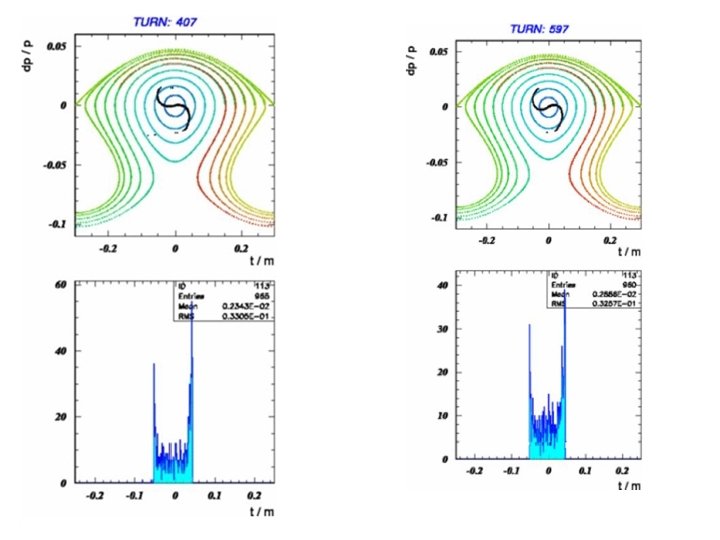
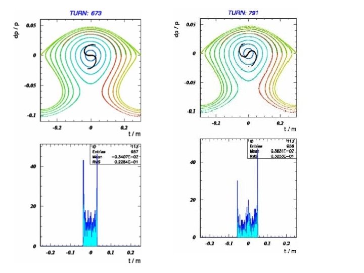
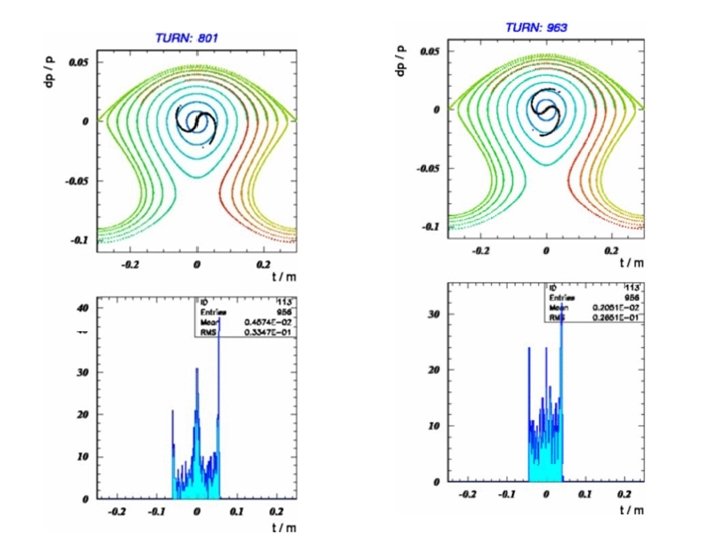
Some problems arise: Evolution of longitudinal phase space after injection of post LWFA bunch ( 10 fs) into the ANKA ring (top left to botom right) for a maximal initial energy deviation p= ± 1%. Simulations were carried with N=10000 particles. During circulation in the present generation light source ring ultra-short pulses injected after LWFA will be spread out inside RF Bucket and partly lost due to synchrotron motion filamentation (compaction factor) caused by large momentum spread of injected bunch Evolution of longitudinal phase space of beam with momentum spread p= ± 3% exceeding RF acceptance of the ring. Particles are lost by moving out of RF Bucket.
More problems may lead to emittance growth and bunch broadening in the ring Due to the expanding of electrons in the plasma “bubble” with large divergence x and large momentum spread E of initial bunch extracted from electron plasma the effective normalized beam emittance norm will grow significantly according to 2 norm = 2 ( 2 E 2 x + 2) approximating beam divergence as x = x s where s is distance from the laser target, the normalized emittance should grow with distance as square of product of momentum spread and distance from the target ( E s)2 2 norm 2 ( 2 E 4 x s 2 + 2) Growth of normalized emittance should lead to increase of bunch length due to synchrotron-betatron coupling in dispersion sections of a ring. Laser driven e-gun could be immersed into a strong field solenoids with short focusing distance in order to limit effect of beam emittance growth. At low energies (<100 Me. V) multi-bunch instability and Intra-beam scattering would contribute to bunch length increasing Evolution of phase space for electron beam travelling through neutral Li gas sampled and compared at: a) Initial phase space distribution, c) 130 -150 m as initial and final, respectively.
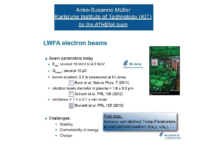
expected parameters of electron beam generated by Laser Wake-field accelerator The pulse width of single spike electron bunch extracted from the Laser Wake Field Accelerator and after bunch compression should be expected in a range of 1 to 10 fs while energy spread of such ultra-short spike could be varied in a range of E 1% to 3% The bunch charge of single spike might be in a range of Q 20 30 p. C and should not exceed Q 200 p. C in order to fulfill conditions for a single spike. The pulse duration of bunch with charge of Q 1 n. C might reach 30 100 fs The laser spot footprint is less than 1 m and initial beam spot might be expected as small as x, y 1 m More realistic to expect that due to fast expansion of electrons in a plasma with large angular and momentum spread the beam size should be defined at expanded bubble surface where electrons leave dense plasma x, y 10 m ( this number should be ckecked -? ) The beam divergence is rather high x , y 1 ÷ 3 mr. Thus, emittance of electron spikes after LWFA (1 Ge. V) might be estimated as 10 30 nm rad ( 20 mm·mr )
Definition of a problem • beam after LWFA is NOT fitted for storage and accumulation in present generation rings • energy spread of post LWFA beam E (1 3)% exceeds momentum spread of beam injected and stored in existing light sources ( E 0. 1%) • utlra short e-pulses after LWFA ( 10 fs) will be spread out in existing storage rings to rf 1 ns due to RF filamentation process • LWFA beam will be destroyed if one would attempt to inject it into present generation light sources • Dedicated rings with new features are required • before to build LWFA facility one should study how is it possible to accept beam after LWFA • experimental "proof of principles" is required of stable rotation of ultra-short ( fs) bunches as well as wide-momentum spread beam in a circular rings would be a solid ground for further R&D on LWFA facilities
Prototypes
Prototypes
Prototypes Compact Low energy electron storage rings for inverse Compton Scattering • • D. E. Monston (MIT, USA) “Inverse Compton Scattering: A Small Revolution in X-Ray Sources and Applications“ Inverse Compton Scattering x-ray (ICSX) sources. LINAC -- driver for electron beam… Energy of scattered quants under head-on collision
Prototypes ICSX Project ( Indiana University, USA ) • 20 – 100 Me. V (up to 600 Me. V) e-synchrotron. Ring circumference = 20 m • Four fold symmetry, Four 90 bending magnets, =2 m (D=2. 5 m) Four 3 m long straigth sections • Two sets of focusing damping wigglers -- three gradient rectangular dipoles each set (either four bends of chican type) located at opposite straights • Chican magnet system to interact e-beam with laser pulses for inverse Compton scattering • Tunable momentum compaction factor ( 1. . 0, 58) by adjusting field strength of damping wigglers • Debunch RF LINAC beam bunches • Compress LINAC pulses by operation at 0 ( quasi-isochronous mode) • Energy spread of ICSX ring - combined effect of SR and CS • Electron loses significant part of energy due to stochastic nature of Compton scattering – strong excitaiton of syncrhotron oscillations -- large momentum spread > 1. 5% (e –beam energy E = 50 Me. V) • Large Dispersion of ICSX ring (D>2 m) would lead to SMALL geometric Momentum Acceptance • IBS (Touschek life time), vacuum conditions for low energy electrons require additional studies • Unfortunately, post LWFA beam with large momentum spread not fitted to the ICSX ring
Prototypes IOTA ring (ASTA proposals 2013) IOTA ring layout IOTA lattice The IOTA ring is designed for the proof-of-principle experiment of the nonlinear integrable optics at the ASTA facility. It is desirable to accommodate more experiments, such as the nonlinear focusing with electron beam lens and optical stochastic cooling. four 2 m nonlinear magnet insertions sections Optical stochastic experiment at IOTA (2014)
FLUTE LINAC as injector of low energy Electron beam
The VLA-c. SR ring should provide possibility for EXPERIMENTS and TESTS with electron beam in a wide energy range from 50 to 500 Me. V with objectives: 1) Ring operation with ULTRA SHORT PULSES • • preserve pulse structure of ultra-short bunches with pulse width 30 fs Charge of single spike could be in the range of Q = 20 ÷ 200 p. C in order to fulfill conditions for a single spike injection after the LWFA while the pulse duration of bunch with charge of Q 1 n. C might reach 100 fs. 2) Ring operation with beam of large momentum spread • feasibility studies of a ring with large Momentum Acceptance P/P > 10 % • • • and reasonably large Dynamic Aperture to store the electrons after the LWFA with emittance of about x, y 10 to 30 nm rad (rms) and momentum spread of E ± 1 % (realistic value) up to ± 3 % (if possible et al) 3) Is it feasible and realistic to COMBINE ring operation with beam of large momentum spread AND ultra short bunch width ? ? ?
At beam energy 50 Me. V the SR dumping time is about SR 20 s and one can consider processes associated with SR as SLOW ADIABATIC DAMPING with respect to betatron and synchrotron motion as well as to stochastic cooling processes in a dedicated test ring Available energy range of the LWFA ring from 50 up to 500 Me. V would allow to study injection, circulation and storage of ultra-short bunches as well as beam with large momentum spread after the FLUTE at low energies – without interfering with Synchrotron radiation damping. Also one could investigate beam sirculation and storage after the laser wake-field accelerator at high energies up to 500 Me. V. e-beam SR Damping time Energy in horizontal in vertical in longitudinal phase space plane phase space (bunch length – energy spread) 50 Me. V 20 s 19. 6 s 9. 7 s 100 Me. V 2. 5 s 2. 45 s 1. 2 s 200 Me. V 0. 32 s 0. 31 s 0. 15 s 400 Me. V 39 ms 38 ms 19 ms 500 Me. V 20 ms 19. 7 ms
Why FLUTE as a test injector, why not a conventional Light Source facility ? (1) First of all, FLUTE is a research test bench DEDICATED to R D while user facilities are overbooked and can not be easily modified and even can NOT be modified et al in order to fulfil very specific requirements for post LWFA ring (2) Beam parameters after FLUTE might be easily fitted to those after the LWFA: Parameters of FLUTE beam: • Beam energy 40 to 90 Me. V • Bunch length (rms) from = 5 fs (Q= 1 p. C charge) to <100 fs (Q= 100 p. C charge) • momentum spread (rms) E 1% • repetition rate 10 Hz • FLUTE beam emittance x, y < 10 nm rad (rms) • Parameters of FLUTE beam are more reproducable and stable than those from LWFA. Ideal for systematic R&D (3) The SR dumping time is SR 20 40 s at E=50 Me. V, i. e. SR is SLOW ADIABATIC process with respect to betatron and synchrotron oscillations as well as possible stochastic cooling (4) With beam after FLUTE one could study short ( fs) as well as wide momentum spread ( 2%) bunches indepenent on SR (5) Ring could operate in an energy range from 50 to 500 Me. V (6) Next step towards post LWFA facility would be an injection of 500 Me. V e-beam after the LWFA into the VLA-c. SR ring
Layout of FLUTE and post-LWFA ring in the Bunker Experimental Hall Ring is fitted into the FLUTE bunker and might be located above the LINAC at second level (height 5 m) Bunker S =210 m 2 Area =15 m 14 m h = 5 m with radiation protection diagonal ~21 m COST saving project NO additional radiation protection NO additional costs for building and moderate cost for engineering Laser clean room 1 Experimental room Control room Rooms around Bunker are available to locate power supplies, electronics and engineering equipment
REASONS to use FLUTE as an injector for the low energy post LWFA test storage ring • At 50 Me. V the SR damping time is 20 s and SR is SLOW ADIABATIC process with respect to betatron and synchrotron motion • Using FLUTE as an injector one can systematically study effects associated with circulation of large momentum spread beam as well as with rotation of ultra-short bunches without being affected by SR • Optic stochastic cooling processes might be studied in a dedicated low energy test ring • Using FLUTE as an injector one can simulate beam conditions after LWFA but more reproducable and stable than those from LWFA • Energy range from 50 Me. V up to 500 Me. V would allow to test low energy beam after FLUTE as well as beam after Laser Wake Field Accelerator • Cost saving project. Compact ring dimensions help to locate ring in existing Bunker vault where FLUTE is installed. Radiation protection, communications and other engineering equipment already provided either might be easily accommodated
VLA-c. SR lattice with relaxed parameters (ring geometry fitted to the FLUTE Bunker)
VLA_c. SR ring lattice with relaxed parameters ” 3 Q_SPLIT_SHORT_5” lattice version fitted to the FLUTE Bunker 15 14 m Parameters of „ 21_3, 6, 9“ lattice are shown in brackets Circumference [m] 44. 112 (41) Horizontal Tune 5. 8438 (11. 31) Vertical Tune 8. 4605 (2. 61) SXT and OCT L=2 m are not shown Nat. hor. Chromaticity 16 ( 27) Nat. vert. Chromaticity 21 ( 19) Chr / Cell 4 / 5. 2 ( 6. 8 / ( 4. 8) L = 3 m MAX-IV Chroma (h/v) 50 / 44 MAX-IV CHR / Cell 2. 5 / 2. 2 NSLS-II CHR / Cell < 3 ESRF-100 pm / Cell 3. 6 / 2. 7 Earlier version „VLA_21_3, 6, 9“ Mom compact. 6. 034 E-03 (3. 6 E-03) Hor. damp. partition Jx 1. 397 (0. 97) Energy 50 Me. V Rad. energy/turn [Me. V] 0. 00 Natural Emittance [nm] 0. 18 (0. 1) Appr. vert. Emittance [pm] 0. 31 Natural energy spread 4. 24 E-05 Hor. damping time [s] 24 (20) Vert. damping time [s] 34 (19) Long. damping time [s] 21 (9) Radiation Integrals: I 1 [m] 2. 662 E-01 I 2 [1/m] 4. 935 E+00 I 3 [1/m 2] 3. 876 E+00 I 4 [1/m] -1. 96 E+00 I 5 [1/m] 3. 389 E-01 13, 204 m Blue – bends Red – quads Green Sextupoles Elements are not in scale
Ring Lattice “ 3 Q_SPLIT_SHORT_5”. C = 44. 112 m Betatron tune Qx=5. 8438 Qy= 8. 4605
Table 1. Parameters of VLA-c. SR and MAX-IV rings
Table 1. Parameters of VLA-c. SR and MAX-IV rings (cont. )
Parameters of „ 21_3, 6, 9“ lattice are shown in brackets ” 3 Q_SPLIT_SHORT_5” lattice version. One Cell. A-4 B Q 5 A -5 B Q 1 Q 2 Q 3 S 4 A-S 4 B S 5 A-S Q 6 A-6 Element dimensions not in scale B 22. 5 8 Q 7 B-6 5 BA Q 5 A -S 4 B Q 3 Q 2 Q 1 MAX-IV Kq < 4 m-2 „ 3 Q_SHORT_5“ cell All sextupoles are shown 6, 602 m A 22. 5 S 4 A B -S 5 B-4 -S 5 Q 4 S 5 A G < 3 30 T/m SXT effective length 15 -10 -15 cm (15) 7 Q B Quads strength Kq < 16 m-2 (30) Chromatic SXT Integr. Strength Ks·L (m-2) 4 A-4 -4 B= +2. 2 / 2. 2 (+33) 5 A-5 -5 B= 11. 3 / 11. 3 (-35) 6 A-6 -6 B = +2. 1 / 2. 1 (+34) Ks L < 11 m-2 (40) (MAX-IV S < 22 m-2) Q -S 6 • Gradient Bends (blue) 5 -S 5 B S 6 • Quads (red) A-S 6 B • Chromatic SXT(green) • Combined function magnets (Q+S) • QUADS in dispersion sections are splitted in doublets • Chromatic SXT are splitted in triplets • Central SXT of each triplet is flanked between quads -S 6 Q 7= 2. 437 ( 12. 1) Q 8=+8. 460 (+26. 2) Q 4 Q 6 A=+11. 65 (+28. 9) Q 6 B=+11. 6 5 22. 5 S 6 A Quads eff. length Q 1, 3 = 15 cm (15) Q 2, 7, 8 = 20 cm Q 4 A-4 B 15 -15 cm Q 5 A-5 B 15 -15 cm Q 6 A-6 B 15 -15 cm Q 1= 2. 138 ( 5. 8) Q 2=+6. 736 (+18. 2) Q 3= 4. 01 ( 13. 9) Q 4 A=+11. 7 (+28. 7) Q 4 B=+11. 485 Q 5 A= 15. 305 ( 20) Q 5 B= 16. 435 L/2=1 m . 5 GRAD= (0, 67 6, 7) T/m Quads strentgh (m-2) 22 E=50 500 Me. V B R=0. 167 1, 67 T m BENDS TH = 22. 5 (22. 5 ) L=50 cm (30) B = 0. 13 1, 3 T (0. 22 -2, 2) R =1. 273 m (0. 764) 1= 2=11. 25 (0) STR= 3. 99 m-2 (0) Lq=1 m Length L=11. 028 m
Lattice “ 3 Q_SPLIT_SHORT_5”. half- cell Chromaticity x= 16 y = 21 Betatron tune Qx=5. 8438 Qy= 8. 4605 Phase adv/cell x=1. 461 2 =2. 922 y=2. 1151 2 =4. 2303 D=25 cm Ph adv(half-cell) x=0. 7305 2 =1. 461 ( x ¾) y=1. 084 2 =2. 1151 x(S 6 B-S 4 A)=(0. 64 0. 203) 2 =0. 44 2 = 0. 88 1 x(S 6 -S 4)=(0. 636 0. 208) 2 =0. 43 2 = 0. 86 x(S 6 A-S 4 B)=(0. 63 0. 21) 2 =0. 42 2 = 0. 84 Minimization of linear RDT by proper choice of betatron phase advance and mirror symmetry Second and third order Chromaticity terms are reduced Split quads and sextupoles applied to reduce overfocusing Horizontal and vertical betatron functions are WELL separated Q 1 Q 2 Q 3 BM Q 4 A - Q 4 B Q 5 A-Q 5 B Q 6 A-Q 6 B BM Q 7 Q 8 S 11 S 21 S 3 S 41 S 4 A-S 4 B S 51 S 5 A-S 5 B S 61 S 6 A-S 6 B S 62 S 7 S 81 S 8
Lattice “ 3 Q_SPLIT_SHORT_5” One cell Betatron tune Qx=5. 8438 Qy= 8. 4605 D=25 cm VLA _21_3, 6, 9 Phase adv/cell x=1. 461 2 =2. 922 y=2. 1151 2 =4. 2303 Mirror symmetry Q 1 Q 2 Q 3 BM Q 4 A-4 B Q 5 A-5 B Q 6 A-6 B BM Q 7 Q 8 Q 7 BM Q 4 A-4 B Q 5 A-5 B Q 6 A-6 B BM Q 3 Q 2 Q 1
An envelope of wide momentum spread beam Lattice “ 3 Q_SPLIT_SHORT_5”. One cell Post-LWFA beam with large momentum spread y, =10 nm·rad (rms) x =10 nm·rad (rms) Required MA > ± 3% Vertical envelope p =1% (rms) Horizontal envelope Dx = 24 cm y, =10 nm·rad (rms) x=10 nm·rad (rms) p =2% (rms) Required MA > ± 6% L, m Beam envelope of a beam with small momentum spread Expected beam envelope at equilibrium (damping time > 20 s) IBS not included y, =10 nm·rad (rms) x =10 nm·rad (rms) p = 0. 1% (rms) Green – dispersion trajectory p =2% (rms) p 0. 1% Natural Emittance 0. 18 nm Appr. vert. Emittance 0. 3 pm Natural energy spread 4. 2· 10 5
10 fs bunch rotation in the VLA-c. SR (A. -S. Müuller)
Layout of the LWFA ring + phase compressor of CHICAN type Study in progres
Non-linear optics VLA-c. SR lattice with relaxed parameters
Early versions of the VLA-c. SR lattice suffer from non-linear distortion caused by strong over-focusing • • It was necessary to relax strong settings of early versions (lattice „ 21. 3, 6, 9“ as an example) and find compromises between lattice parameters Quadrupole strength of „ 21_3, 6, 9“ lattice Kq>30 m-2 i. e. 10 times MORE of MAX-IV quads (Kq < 4 m-2). . . Chromaticity/cell HIGH, dispersion SMALL Dmax<12 cm and required SXT strength is HIGH (S L 40 m-2 ) Dynamic aperture (on-momentum) is SMALL DAx 5. . +7 mm NOT enough for stable circuation Merit of the „ 3 Q_PLIT_SHORT_5“ lattice • Ring dimensions are fitted to existing FLUTE Bunker while main parameters are improved • Radius of bending magnets is increased, gradient and edge focusing in vertical direction are applied • Quads are splitted in doublets QA-QB, distances between elements are increased • Quads strength reduced from 30 m-2 to Kq<14 m-2 (still few times higher those for MAX-IV) • The compensation of horizontal chromaticity is done by sets of splitted SXT triplets SXA–SX SXB • Ring lattice is modelled to satisfy „ I“ condition for mirror symmetry non-interleaved sextupoles • Max of Dispersion is doubled D=25 cm, integrated SXT strengh reduced S·L<20 m-2 (MAX-IV S L 20 m-2) • Side effect – decreasing of Geometric Momentum Acceptance to MA ± 7% (60 30 mm chamber)
Merit of the “ 3 Q_SPLIT_SHORT_5“ lattice • Chromatic SXT S 4 and S 6 are flanked between quads and located at position of Dmax and Xmax • Phase advance between S 4 and S 6 is close to and Symmetry conditions are applied x(S 6)= x(S 4) D(S 6)=D(S 4) D (S 6)= D (S 4) x(S 6 S 4) • S 5 is positioned in the middle of dispersion section at MAX of vertical y(S 5) and MIN x(S 5) 5 cm • Vertical SXT S 5 has little influence on SXT non-linear terms in horizontal plane • Quads gradients relaxed to <25 T/m at 500 Me. V (MAX-IV Q gradients are <40 T/m) • Half-cell betatron phase advance close to x 3. 5 ( x 1. 75) and Resonance Driving Terms (Qx, 2 Qx, 3 Qx, Qx± 2 Qy) are reduced due to lattice symmetry and periodicity • Quadratic ( 2 x ), Cubic ( 3 x) CHROMA and ADTS are minimized by lattice geometry and harmonic SXT • Dynamic aperture ± 5 mm of early lattice versions („ 21_3, 6, 9 “) is OPENED to -14. . +18 mm (3 Q_SPLIT_SHORT_5) • DA for off-momentum particles ( ± 5%) is enough for stable circulation of wide momentum spread beam • Octupoles and decapoles should be added to VLA-c. SR lattice to suppress ADTS, quadratic and cubic chromaticities etc. but its strengh must be limited in order to preserve stability of betatgron motion Full suppresion of ADTS by octupoles leads to reduction of DA. Full suppression of second order chromaticity by octupoles leads to increase of ADTS and cubic chromaticity terms. As a result the MA is improved but DA is reduced •
DYNAMIC APERTURE. Lattice “ 3 Q_SPLIT_SHORT_5” Chromatic SXT 3 Q_SPLIT_SHORT_5 Chromatic SXT DAy = ± 5 mm (± 50 y) axial injection might be possible 3 Q_SPLIT_SHORT_5 Offmomentum =+3% ONmomentum Chamber 60 x 40 mm SXT int. strength S L 4 A-4 -4 B=+2/+2/+2 m-2 5 A-5 -5 B=-11/-11 m-2 6 A-6 -6 B=+2/+2/+2 m-2 DAx = 14…+18 mm (± 100 x) Ax 120 mm·mr With errors Ax 50 mm·mr Ax (MAX-IV) < 10 mm·mr Chromatic SXT 3 Q_SPLIT_SHORT_5 DA. Lattice early versions Chromatic SXT ON-momentum CHR+HRM SXT + OCT Offmomentum = 3% ON-momentum „ 21 -9“ SXT int-str S 4 L=+33 m-2 S 5 L= 35 m-2 S 6 L=+34 m-2 „ 21 -3“ Chamber 60 x 40 mm
Off-momentum dynamic aperture as function of energy deviation Lattice “ 3 Q_SPLIT_SHORT_5” CHR SXT CHR+HRM SXT Chromatic Sextupoles 3 Q_SPLIT_SHORT_5 OFF-momentum Acceptance horizontal plane MAx = 6%. . +6% SXT int. strength S L 4 A-4 -4 B=+2/+2/+2 m-2 5 A-5 -5 B=-11/-11 m -2 6 A-6 -6 B=+2/+2/+2 m-2 Chamber 60 x 40 mm 3 Q_SPLIT_SHORT_5 Momentum Acceptance in vertical plane is improved by adjusting harmonic sextupoles OFF-momentum Acceptance vertical plane MAy= 4%. . +5% Chamber 60 x 40 mm MAy = 8%. . +8% early versions of VLA-c. SR lattice. strong settings of quads cause over-focusing and non-linear distortions CHR SXT S 4 L=+33 m-2 S 5 L= 35 m-2 S 6 L=+34 m-2 „ 21 -3“ CHR+HRM SXT+OCT „ 21 -9“
Betatron tune diagram. Lattice “ 3 Q_SPLIT_SHORT_5” Chromatic Sextupoles Momentum deviation = ± 8% = ± 4% Chromatic + Harmonic Sextupoles p= +8% p= +4% Chromatic sextupoles adjusted to vanish first order chromaticity Chromatic and Harmonic sextupoles tuned to vanish first order and minimize second order chromaticity p= 8% p= 4% By adjusting chromatic and harmonic sextupole families one can compensate linear as well as second order chromaticity. Tune deviation for off-momentum particles is reduced and momentum acceptance is improved Harmonic Sextupoles reduce tune spread for same momentum offset in 3 times
Lattice “ 3 Q_SPLIT_SHORT_5”. Betatron tune deviation for off-momentum particles CHR+HRM-SXT+CHR-OCT Chromatic and Harmonic Sextupoles as well as octupoles are applied CHR+HRM-SXT+CHR-OCT Tune diagram Momentum spread = ± 10% Betatron tune deviation is less than Qx, y 0. 03 for off-momentum particles ± 10% Chromatic and Harmonic Sextupoles as well as octupoles located in the dispersion sections of a ring compensate first and second order chromaticity. Octupoles to adjust ADTS are located in the achromatic sections of a ring and switched OFF Integrated octupole strength is limited to K 3 L ± 20 m-3 in order to minimize high-order non-linear distortions and preserve dynamic aperture CHR+HRM-SXT+CHR-OCT
At low energies Beam Life time is limited by scattering on residual gas required pressure for VLA-c. SR P < 10 E-11 torr
VLA-c. SR lattice. Outcome of Feasibiltiy studies • Extensive studies of possible geometry and lattice of the very large acceptance compact storage ring operating in the energy range 50 to 500 Me. V have been provided • The main objective of feasibility studies was to create ring model suitable to store the beam after Laser Wake field accelerator with wide momentum spread ( 1 2%) as well as ultra-short electron bunches in a “ fs” range • More than 40 models of compact ring lattice based on DBA, DBA-FDF, TBA, 5 BA cells etc. have been composed, simulated, analyzed and merit of different configurations has been carefully studied • The DBA-FDF Lattice with relaxed settings and optimized parameters could be accepted as a basis for further Detailed Design studies of the Very Large Acceptance compact Storage Ring • Proposed VLA-c. SR lattice model compromises contradictory conditions -- Small circumference of the ring C 50 m -- Small dispersion D< 15 25 cm -- Large Dynamic Aperture in the dispersion plane DAx > 15 mm -- Large Acceptance in both planes Ax, y > 20 mm mr -- Wide Momentum Acceptance MA 5 10% -- Chromaticity / cell should be limited to /cell < 5 (NSLS-II sets limits for SXT /cell < 3 ) • • The “ I” condition is provided. The mirror symmetry at position of horizontal chromatic sextupoles is satisfied Local maximums of horizontal beta-function and dispersion at position of main chromatic sextupoles help to restrict sextupole strength. Dynamic Aperture is opened significantly from DA= 5. . +6 mm to DA= 15. . +20 mm • Phase advance per cell is adjusted to minimize leading Resonance Driving Terms including high order chromaticity terms. The dynamic aperture for ON- and OFF-momentum particles is enough to store wide energy spread beam • Harmonic sextupole and octupole families should be used for non-linear studies in particular to operate the ring at negative compaction factor, to manipulate with bunch length and shape etc. but OCT strength must be limited
• Appendix
Amplitude dependent tune shift. Lattice “ 3 Q_SPLIT_SHORT_5”. Octupoles located in achromat section of a ring compensate ADTS Tune diagram ADTS tune shift is reduced by Octupoles located in achromat section of a ring Tune diagram ADTS tune shift octupoles OFF =30 mm mr) ( =30 mm mr) horizontal tune shift Vertical tune shift In order to suppress ADTS the integrated octupole strength is increased to K 3 L ± 250 m-3 As a consequence the DA is shrunk in horizontal and vertical planes ONmomentum Offmomentum =+5% Offmomentum = 5%
Lattice ” 3 Q-SPLIT_SHORT_5”. Chromaticity, dynamic aperture and momentum acceptance C=44. 11 m Ring footprint 2 X 2 Y = 13. 202 m (reference orbit) fitted to the FLUTE Bunker 14 15 m Betatron tune Qx= 5. 8438 Qy= 8. 4605 Phase advance x, y/cell x=1. 461 2 =2. 922 y=2. 115 2 = 4. 2302 Ph. adv. x, y/half-cell x=0. 7305 2 =1. 461 ( x 3/4) y=1. 0576 2 = 2. 1151 x(S 6 B-S 4 A)=(0. 64 0. 203) 2 =0. 44 2 = 0. 88 1 x(S 6 -S 4)=(0. 636 0. 208) 2 =0. 43 2 = 0. 86 x(S 6 A-S 4 B)=(0. 63 0. 21) 2 =0. 42 2 = 0. 84 off-momentum tune shift Qx, y= 1 + 2 2 + 3 3+… Natural Chromaticity 3 Q_SPLIT_SHORT_5 Chromatic sextupoles 3 Q_SPLIT_SHORT-5 Linear chrom hor/vert 1 Quadr. Chr. h/v 2 ( / , D/ ) Cubic chroma hor/vert 3 Off-momentum betatron tune shift 1 x= 16. 6 1 y= 20. 9 2 x= 309 2 y= 94 3 x= 31 107 3 y= 3 162 1 x = +0. 01 1 y = +0. 01 2 x = 14 2 y = 98 3 x= 21 3 y= 497 CHR + HRM sextupoles DAX =± 18 mm 2 a 2 b=60 40 mm Moment. Accept. DAY =± 7. 5 mm MAX= 0. 5%. . 3% 2 a 2 b=60 40 mm MAY = 0. 5%. . 2% HRM SXT minimize 2 x, y 3 Q_SPLIT_SHORT-5 1 x= 0. 03 1 x= 0. 01 1 y= 0. 01 1 y= 0. 05 2 x= +0. 8 2 x= + 0. 27 2 y= 11. 5 2 y= 1. 32 3 x= 3 3 y= +84 Qx 0. 1( = ± 0. 5%) Qx 0. 03( =± 4%) Qx 0. 02( =± 8%) Qy 0. 1( = ± 0. 5%) Qy 0. 1( =± 3%) Qy 0. 1( =± 8%) Dynam. Aperture CHR+HRM SXT + OCT-ADTS DAX= 14 18 mm DAX= 8. . 12 mm MAX = 8%. . 6% DAY = ± 6 mm MAX= 6%. . 6% MAY = 4. 5%. . 6% MAY = 8%. . 9% 3 x= +19 3 y= +126 Qx 0. 02( =± 8%) Qy 0. 1( =± 8%) DAX = 8. . 10 mm DAY =± 6 mm MAX = 6%. . 8% MAY = 7%. . 8%
Lattice ” 3 Q-SPLIT_SHORT_5”. Quads, sextupole and octupole settings off-momentum tune shift Qx, y= 1 + 2 2 + 3 3+… Natural Chromaticity Chromatic sextupoles 3 Q_SPLIT_SHORT_5 3 Q_SPLIT_ SHORT-5 CHR + HRM sextupoles 3 Q_SPLIT_SHORT-5 CHR+HRM SXT + OCT-ADTS HRM SXT minimize 2 x, y Sextupole Integrated Strength b 3 LS (m 2) b 3=(1/BR) 2 B/ R 2 LS – SXT Length Total SXT Str. integrat b 3 LS(m-2) SXT OFF S 1= 0 S 11=0 QUADS S 2=0 S 21=0 S 3=0 S 1= 1. 613 S 11= 0. 881 S 1=+4. 939 OC 1= 62 S 2=+0. 914 S 11=+2. 126 OC 11= 36 S 21= 1. 083 S 2 = 0. 065 OC 2= 39 S 3= +2. 293 S 21= 5. 518 OC 21= 191 Q 1= 2. 138 m-2 S 41= 0 S 41= 17. 022 S 3 = 1. 813 OC 3=+255 Q 2= +6. 736 S 4 A = +2. 21 m-2 S 4 A = +5. 246 S 41= 17. 07 Q 3= 4. 01 S 4 = +2. 2 S 4 = +2. 659 S 4 A = +5. 273 S 4 B = +2. 2 S 4 B = +3. 287 Q 4 A=+11. 7 S 4 = +2. 729 S 51 = 0 S 51 = +4. 621 Q 4 B=+11. 485 S 5 A = 11. 25 S 5 A = 2. 669 S 4 B = +3. 249 Q 5 A= 15. 305 S 5 = 11. 25 S 5 = 10. 127 S 51 = +3. 485 Q 5 B= 16. 435 S 5 B = 11. 25 S 5 B = 12. 223 S 5 A = 3. 116 Q 6 A= +11. 65 S 61= 0 S 5 = 10. 046 S 61= 4. 710 Q 6 B= +11. 65 S 6 A = +2. 11 S 6 A = +6. 786 S 5 B = 12. 033 S 6 = +2. 11 S 6 = +3. 080 S 61= 4. 232 Q 7= 2. 437 S 6 A = +7. 039 S 6 B = +2. 11 S 6 B = +2. 241 Q 8= +8. 460 S 6 = +3. 136 S 62= 2. 125 S 6 B = +2. 235 S 62= 0 S 7= 1. 139 S 62= 2. 280 S 81= 1. 547 S 8= + 1. 645 S 7=0 S 7=+2. 966 OC 7= 133 S 81=0 S 81=+0. 238 OC 81= 67 S 8= 0 S 8 = 4. 390 OC 8=+168 0 =3261 = 5748 =6187
Lattice ” 3 Q-SPLIT_SHORT_5” Resonance Driving Terms off-momentum tune shift Qx, y= 1 + 2 2 + 3 3+… Natural Chromaticity 3 Q_SPLIT_SHORT_5 Chromatic sextupoles 3 Q_SPLIT_SHORT-5 RDT H 21000 (Qx) RDT H 30000 (3 Qx) RDT H 10110 (Qx) (Qx 2 Qy) H 10020 (Qx 2 Qy) H 10200 Beta-beat / (2 QX) H 20001 (2 QY) H 00201 H 10002 (Qx) 2 D/ 2 ADTS QXX ADTS QXY ADTS QYY CHR + HRM sextupoles CHR+HRM SXT + OCT-ADTS 3 Q_SPLIT_SHORT-5 HRM SXT minimize 2 x, y H 21000= 0 H 210000= 2. 36 H 21000= 6. 11 H 21000 = 6. 69 h 30000= 0 h 30000= 6. 08 h 30000= 3. 54 h 30000 = 1. 89 H 10110= 0 H 10110= 3. 38 H 10110=4. 57 H 10110 = 16. 3 h 10020 = 0. h 10020 = 2. 66 h 10020 =1. 21 h 10020 = 1. 36 h 10200 = 0. h 10200= 0. 72 h 10200= 6. 53 h 10200= 1. 99 h 20001 = 13. 6 h 20001 = 2. 26 h 20001 = 0. 0 h 20001 = 0. 48 h 00201 = 1. 67 h 00201 = 0. 91 h 00201 = 0. 24 h 00201 = 0. 25 h 10002= 0. 07 h 10002 = 0. 07 h 10002 = 0. 17 h 10002 = 0. 21 QXX = 0 QXY = 0 QYY = 0 QXX = 1100 QXX = 430 QXY = 752 QXY = 1929 QYY = 402 QYY = 1084 QXX = 0 QXY = 0 QYY = 0
Table 2. Parameters of VLA-c. SR magnetic elements
Table 2. Parameters of VLA-c. SR magnetic elements (cont. )
Layout of the LWFA ring + phase compressor of CHICAN type chican
Lattice of the LWFA ring + phase compressor of CHICAN type Half-ring
ON- and OFF- momentum dynamic aperture Lattice “ 3 Q_SPLIT_SHORT_5”. Chromatic + harmonic sextupoles CHR+HRM SXT 3 Q_SPLIT_SHORT_5 CHR+HRM SXT ON-momentum Off-momentum =+5% Chamber 60 x 40 mm CHR+HRM SXT Chromatic and Harmonic sextupoles tuned to vanish first and second order chromaticity, imrpove momentum acceptance and minimize Resonance Driving Terms 3 Q_SPLIT_SHORT_5 Off-momentum = 5% Chamber 60 x 40 mm
Prototypes IOTA ring - 2012 The IOTA ring is designed for the proof-of-principle experiment of the nonlinear integrable optics at the ASTA facility. It is desirable to accommodate more experiments, such as the nonlinear focusing with electron beam lens and optical stochastic cooling. These options demanded incorporation of a 5 m-long straight section. The stretched ring includes two 5 m long and four 2 m nonlinear magnet insertions sections. The e- beam energy is 150 Me. V. IOTA - 2012
IOTA Ring layout, IPAC 2012, New Orlean ( USA) S. Nagaitsev Experiments with electron lenses and with non-linear magnets
IOTA ring - 2012 IOTA - 2012
Design of IOTA (Integrable Optics Test Accelerator) IOTA ring layout – 22 May 2014
Optical stochastic experiment at IOTA (2014)