MANDAVA INSTITUTE OF ENGINEERING AND TECHNOLOGY Approved by

MANDAVA INSTITUTE OF ENGINEERING AND TECHNOLOGY (Approved by A. I. C. T. C, Affiliated JNTUK KAKINADA) Vidya Nagar , Jaggayapet 521175 ANDRA PRADESH Under the esteemed guidelines of P. NARENDRA BABU, M. Tech Assistant Professor M. SUNEETHA , M. Tech Assistant Professor Department Of Civil Engineering

PROJECT TITLE Computer Aided Structural Analysis, Design and Drawing of Proposed Shopping Mall Building SUBMITTED BY: NAME: HALLTICKET No. BHARAT KUMAR MANDAL 13 FF 1 A 0106 DINESH NEUPANE 13 FF 1 A 0107 SAROJ KUMAR SAH 13 FF 1 A 0124 RUPESH KUMAR YADAV 13 FF 1 A 0122 SANAPALA SAI KRISHNA SHAIK NAGULMEERA 13 FF 1 A 0123 14 FF 5 A 0107

TEAM MEMBER BHARAT KUMAR MANDAL DINESH NEUPANE RUPESH K. YADAV 13 FF 1 A 0106 13 FF 1 A 0107 13 FF 1 A 0122 13 FF 1 A 0124 S. SAIKRISHNA SAROJ KUMAR SAH 13 FF 1 A 0123 13 FF 1 A 0124 SHAIK NAGULMEERA 14 FF 5 A 0107

WITH STRONG SUPPORT OF G. SRINIVASULU PRINCIPAL P. NARENDRA BABU M. SUNEETHA HOD OF CIVIL DEPARTMENT ASSISTANT PROFESSOR

ABSTRACT The aim of this project is study of finding better techniques for creating geometry of a commercial complex building planning preliminary architectural, structural and construction drawing for tender preparation using software.

ASSUMPTION AND NOTATIONS Assumptions and Notations used: The notations adopted throughout the work is same IS-456 -2000. Assumptions in Design: Using partial safety factor for loads in accordance with clause 36. 4 of IS-456 -2000 as ϒt=1. 5 Partial safety factor for material in accordance with clause 36. 4. 2 is IS-456 -2000 is taken as 1. 5 for concre and 1. 15 for steel. Using partial safety factors in accordance with clause 36. 4 of IS-456 -2000 combination of load. D. L+L. L. 1. 5 D. L+L. L+W. L 1. 2 Density of materials used: MATERIAL: DENSITY ii) Reinforced iii) Flooring material (c. m) iv) Brick masonry v) Fly ash LIVE LOADS: In accordance with IS. 875 -86 i) Live load on slabs ii) Live load on passage iii) Live load on stairs = 20. 0 KN/m 2 = 4. 0 KN/m 2 i) Plain concrete 24. 0 KN/m 3 25. 0 KN/m 3 20. 0 KN/m 3 19. 0 KN/m 3 5. 0 KN/m 3

DESIGN CONSTANTS: Using M 30 and Fe 415 grade of concrete and steel for beams, slabs, footings, columns. Therefore: fck = Characteristic strength for M 30 -30 N/mm 2 fy = Characteristic strength of steel-415 N/mm 2 Assumptions Regarding Design: Slab is assumed to be continuous over interior support and partially fixed on edges, due to monolithic construction and due to construction of walls over it. Beams are assumed to be continuous over interior support and they frame in to the column at ends. Assumptions on design: M 20 grade is used in designing unless specified. Tor steel Fe 415 is used for the main reinforcement. Tor steel Fe 415 and steel is used for the distribution reinforcement. Mild steel Fe 230 is used for shear reinforcement.

SYMBOLS Symbols: ` The following symbols has been used in our project and its meaning is clearly mentioned respective to it: A -Area Ast - Area of steel b - Breadth of beam or shorter dimension of rectangular column D -Overall depth of beam or slab DL -Dead load d 1 -effective depth of slab or beam D - overall depth of beam or slab Mumax -moment of resistance factor Fck -characters tic compressive strength Fy -characteristic strength of of steel Ld -devlopment length LL -live load Lx -length of shorter side of slab Ly - length of longer side of slab B. M. -bending moment Mu -factored bending moment Md -design moment Mf -modification factor Mx -mid span bending moment along short span My - mid span bending moment alonger span M’x -support bending moment along short span M’y - support bending moment alonger span Pt -percentage of steel W -total design load

Wd Tcmax Tv Tv ɸ Pu Mulim Mux, Muy Ac Asc Mux 1 moment -factored load -maximum shear stress in concrete with shear -shear stress in concrete -nominal shear stress -diameter of bar -factored axial load -limiting moment of resistance of a section without compression reinforcement -moment about X and Y axis due to design loads - area of concrete& -area of longitudinal reinforcement for column -maximum uniaxial moment capacity for an axial load of pu, bending x and Y axis respectively

CONTENT UNIT 1: INTRODUCTION UNIT 2: LOADING UNIT 3: DESIGN OF BEAMS UNIT 4: DESIGN OF COLUMNS UNIT 5: DESIGN OF SLABS UNIT 6: SOFTWARE UNIT 7: PLAN AND ELEVATION

UNIT 1: INTRODUCTION Building construction is the engineering deals with the construction of building such as commercial building. In a simple building can be define as an enclose space by walls with roof, food, cloth and the basic needs of human beings. In the early ancient times humans lived in caves, over trees or under trees, to protect themselves from wild animals, rain, sun, etc. as the times passed as humans being started living in huts made of timber branches. The shelters of those old have been developed nowadays into beautiful houses. Rich people live in sophisticated condition houses. A building frame consists of number of bays and storey. A multi-storey, multi-panelled frame is a complicated statically intermediate structure. A design of R. C building of G+6 storey frame work is taken up. The building in plan (34 x 50) consists of columns built monolithically forming a network. The size of building is 20 x 35 m. The number of columns are 40. It is commercial complex. The design is made using software on structural analysis design (staad-pro). The building subjected to both the vertical loads as well as horizontal loads. The vertical load consists of dead load of structural components such as beams, columns, slabs etc. and live loads. The horizontal load consists of the wind forces thus building is designed for dead load, live load and wind load as per IS 875. The building is designed as two dimensional vertical frame and analysed for the maximum and minimum bending moments and shear forces by trial and error methods as per IS 456 -2000. The help is taken by software available in institute and the computations of loads, moments and shear forces and obtained from this software.

Statement of Project Salient features: Utility of building : Commercial complex No of stories : G+6 Shape of the building : Rectangular No of staircases : 2 No of lifts : 2 No of Escalator : 2 Type of construction : R. C. C framed structure Types of walls : brick wall Geometric details: Ground floor Floor to floor height Height of plinth Depth of foundation : 3 m. : 0. 6 m : 500 mm Concrete grade All steel grades Bearing capacity of soil : M 30 : Fe 415 grade : 300 KN/M 2 Materials:

Method of analysis of statistically indeterminate portal frames: Ø Method of flexibility coefficients. ØSlope displacements methods(iterative methods) ØMoment distribution method ØKane’s method ØCantilever method ØPortal method ØMatrix method ØSTAAD Pro

UNIT 2: LOADING Building Loads Categorized by Orientation: Ø Ø Ø Ø Types of loads on an hypothetical building are as follows. Vertical Loads Dead (gravity) Live (gravity) Snow(gravity) Wind(uplift on roof) Seismic and wind (overturning) Seismic( vertical ground motion) Horizontal (Lateral) Loads: Ø Ø Ø Direction of loads is horizontal w. r. t to the building. Wind Seismic(horizontal ground motion) Flood(static and dynamic hydraulic forces Soil(active lateral pressure)

DESIGN LOAD FOR COMMERCIAL BUILDING Dead Load Live Load Dead load calculation Weight=Volume x Density Self weight floor finish=0. 12*25+1=3 kn/m^2 The above example shows a sample calculation of dead load. Dead load is calculated as per IS 875 part 1 Live loads are calculated as per IS 875 part 2

Wind load Calculation of wind load as per IS 875 part 3. Design wind speed Vs. =Vb* K 1* K 2* K 3 Where Vb = Basic wind speed (50 m/s for vijayawada) Vz= design wind speed at any height Z in m/s K 1= probability factor (risk coefficient) = (1. 0 for 100 yrs) K 2=terrain height and structure size factor and (0. 89 Catagoriees-4 & Class-A) K 3=topography factor (1 ) Pz = 0. 6 x (Vz)2

FLOOR LOAD

UNIT : DESIGN OF BEAM Beams transfer load from slabs to columns. beams are designed for bending. In general we have two types of beam: single and double. Similar to columns geometry and perimeters of the beams are assigned. Design beam command is assigned analysis is carried out, now reinforcement details are taken. Beam design: A reinforced concrete beam should be able to resist tensile, compressive and shear stress induced in it by loads on the beam. There are three types of reinforced concrete beams 1. Single reinforced beams 2. Double reinforced concrete 3. Flanged beams

ANALYSIS OF SINGLY REINFORCED SECTION STEP 1: Given Data STEP 2: Xu= STEP 3: Find ‘Xumax’ → Type of steel Fe 500 - 0. 46 d Fe 415 - 0. 48 d Fe 250 - 0. 53 d STEP 4: Compare ‘Xu’ and ‘Xumax’ then decide the section whether under balanced or over reinforced section STEP 5: Find corresponding ‘Mu’ based on the type of section. DESIGN OF SINGLY REINFORCED SECTION: STEP 1: Given data STEP 2: Effective span STEP 3: Loads STEP 4: Bending moments and Shear force STEP 5: Check for effective depth STEP 6: Area of tension reinforced STEP 7: Check of shear STEP 8: Check for deflection STEP 9: Detailing for reinforced

ANALYSIS OF DOUBLE REINFORCED SECTION: STEP 1: Find fsc (from d´/d and type of steel) STEP 2: Find Xu Xu= STEP 3: Find ‘Xumax’ STEP 4: Compare ‘Xu’ and ‘Xumax’ then decide the section whether under balanced or over reinforced section STEP 5: Find corresponding ‘Mu’ based on the type of section. DESIGN OF DOUBLE REINFORCED SECTION : STEP 1: Given data ( Effective Span) STEP 2: Bending Moments and Shear force STEP 3: Find Mulimit and compare Mu and Mulimit then decide whether it is to be designed as singly reinforced or double reinforced section. STEP 4: Area of tension reinforced from Mulimit(Ast 1) STEP 5: Area of compression reinforced (Asc) d´/d=? and fsc=? Mu 2=Mu - Mulimit But Mu 2= fsc. Asc(d-d´) Asc=Mu 2/ fsc(d-d´) STEP 7: Area of additional tensile steel(Ast 2) Ast 2=(fsc. Asc)/(0. 87 fy) Total tensile steel (Ast) = Ast 1+Ast 2 STEP 8: Check for shear STEP 9: Check for deflection STEP 10: Detailing of reinforced

ANALYSIS OF T-BEAM : STEP 1: Given data STEP 2: Cross-sectional dimension l/d=15 and assume Su=300 mm STEP 3: Effective span STEP 4: Loads STEP 5: Bending moments(Mu. D) and shear force STEP 6: Effective flange width STEP 7: Moment capacity of flange section(Muf) Muf=0. 36 fckbf. Df(d – 0. 42 Df) STEP 8: Compare Mu. Dand Muf and hence suggest if Xu>Df or xu<Df State whether neutral axis falls within flange, If within the flange, as a rectangular beam If outside the flange Assume Df/xu=0. 43 Mu 2=Muw+Muf Where Muw=Cuw(d – 0. 42 xu) Muf=Cuf(d – Df/2) Compare Mu 2 and Mud then Df/xu<0. 43 If Mu 2 < Mud Ast will be determined by Cuw+Cuf=T 0. 36 fckbwxu+0. 45 fck(bf – bw)yf=0. 87 fy. Ast

UNIT 4: DESIGN OF COLUMNS A column or strut is a compression member, which is used primary to support axial compressive loads and with a height of at least three it is least lateral dimension. A reinforced concrete column is said to be subjected to axially loaded when line of the resultant thrust of loads supported by column is coincident with the line of C. G 0 f the column I the longitudinal direction. Effective length of columns: The effective length of a column depends upon the unsupported length and the boundary conditions of the ends of column due to the conditional of the framing beams and other members. . From IS: 456: 2000 Table – 28 A column may be classified based as follows based on the type of loading: Axially loaded column A column subjected to axial load and uneasily bending column subjected to axial load and biaxial bending

UNIT 5: SLABS 5. 1 INTRODUCTION Slabs are plane structure member whose thickness is small as compare to its length and breadth. Slabs are most frequently used as roof coverage and floors in various shapes such as square, rectangle, circular, triangle, etc. in buildings Slabs supports mainly transverse loads and transfers them to supports (Beams and Walls) by bending action in one or more direction. 5. 2 TYPES OF SLABS: Depending upon the ratio of longer span to shorter span (lx/ly) the slabs are classified as : One-way slab Two -way slab One-way slab: Slabs which are supported on all four sides or edges and the ratio of longer span to shorter span is greater than 2 are called one-way slabs. One-way slabs bends in one direction i. e. along the shorter span and hence it needs main reinforcement in onedirection only. However minimum reinforcement known as distribution reinforcement is provided alonger span above the main reinforcement to distribution load uniformly and to resist temperature and shrinkage stresses. 5. 4 TWO WAY SLAB When the slab is supported on all the four edges and if the ratio of longer span to shorter span is less than or equal to 2, the slab is likely to bend along the two directions and such slabs are called as Two Way Slabs. Main reinforcement have to be designed in both the directions. Two way slabs can be divided into the following categories. Slabs simply supported on all four edges and corners free to lift. Restrained slabs i. e. (slab with fixed or continuous edges) with corners held down.

UNIT 6: SOFTWARE 6. 1 INTRODUCTION This project is mostly based on software and it is essential to know the details about these software’s. List of software’s used Staad pro(v 8 i) Staad foundations 5(v 8 i) Auto cad Autodesk Revit

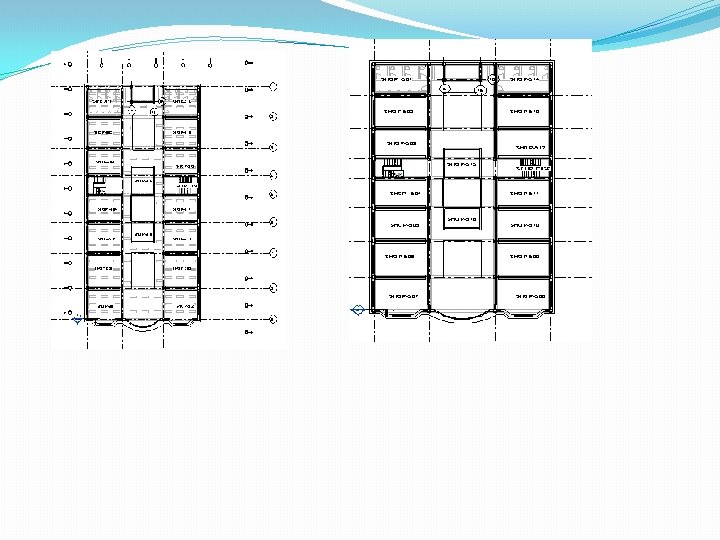
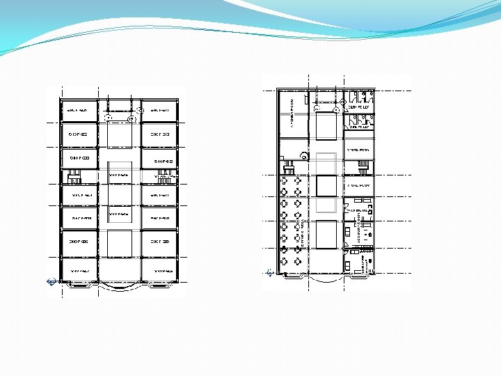
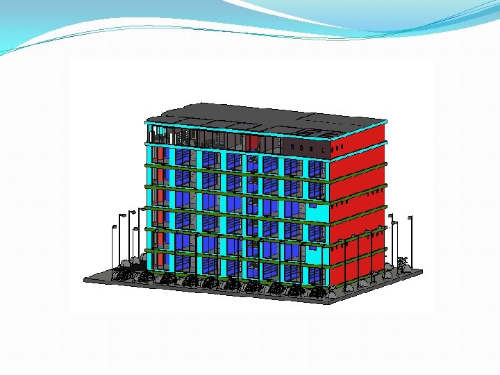
UNIT 7: PALN AND ELEVATION

THANK YOU
- Slides: 29