ITEC 275 Computer Networks Switching Routing and WANs


 and FDM (Frequency Division Multiplexing) are two")


 Availability")


 Based on the previous slide • Test objective. Assess the")
 1. Start capturing network traffic on the protocol analyzer on")
 5. Display data on Network A’s protocol analyzer and verify")
 6. Display data on Network B’s protocol analyzer and verify")
 Host A sends a TCP SYNchronize packet to Host B")


 works with its companion Routing Engine")


 • Allows a host to join a multicast group")
 – Distance Vector Multicast")

 is a family of multicast")
 What is PIM Dense Mode? • Dense mode is used")
 What is PIM Dense Mode? Dense mode PIM is the")

 What is PIM Sparse Mode? • Sparse mode utilizes a")
 What is PIM Sparse Mode? PIM Sparse Mode (PIM-SM) explicitly")


 Field • RFC 2474 redefines the type of service field")
 Field 0 6 Differentiated Services Codepoint Explicit Congestion Notification 0")
 • RSVP complements the IP type-of-service, precedence, DSCP, and traffic-class")
 • IP header type-of-service capabilities and RSVP are examples of")


 is a technique for switching packets")

 queuing store packets when the network")


 combines the best scenarios of priority,")

 NO Packet in Queue? YES Next Queue YES")

 • Congestion avoidance rather than congestion management • Monitors traffic")

 • Cisco feature for classifying and policing traffic on an")


- Slides: 94
ITEC 275 Computer Networks – Switching, Routing, and WANs Week 11 Robert D’Andrea Summer 2017
• Learning Activities Agenda – TDM and FDM differences – Industry Tests – Build and Test a Prototype – Write and Implement a Test Plan – Tools for Testing a Network Design – Multicasting – Qo. S – Queuing and Traffic Shaping
ATM Video Frame Relay, ATM, and MPLS videos: https: //www. youtube. com/watch? v=Sz 1 PThot. OUQ
TDM and FDM TDM (Time Division Multiplexing) and FDM (Frequency Division Multiplexing) are two methods of multiplexing multiple signals into a single carrier. Multiplexing is the process of combining multiple signals into one, in such a manner that each individual signal can be retrieved at the destination. Since multiple signals are occupying the channel, they need to share the resource in some manner.
TDM and FDM The primary difference between FDM and TDM is how they divide the channels. FDM divides the channel into two or more frequency ranges that do not overlap. TDM divides and allocates certain time periods to each channel in an alternating manner. Because of this fact, we can say that TDM, each signal uses all of the bandwidth some of the time, while for FDM, each signal uses a small portion of the bandwidth all of the time.
TDM and FDM 1. FDM divides the channel into multiple, but smaller frequency ranges to accommodate more users, while TDM divides a channel by allocating a time period for each channel. 2. TDM provides much better flexibility compared to FDM. 3. FDM proves much better latency compared to TDM. 4. TDM and FDM can be used in tandem.
FDM
TDM and FDM
Reasons for Network Testing • Verify that the design meets key business and technical goals • Validate LAN and WAN technology and device selections • Verify that a service provider provides the agreedup service • Identify bottlenecks or connectivity problems • Determine optimization techniques that will be necessary
Reasons for Network Testing • Proving that your network design is better than a competing design • Passing an “acceptance test” that gives you approval to go forward with the network implementation • Reassure mangers and co-workers that your design is effective • Identifying any risks that might impede implementation and planning for contingencies • Determine how much additional testing might be required. Will the new system be deployed as a pilot and undergo additional testing before being implemented
Testing Your Network Design • Use industry testing services • Build and test a prototype system • Use third-party and Cisco tools
Respected Independent Test Labs Network Testing Labs' experts write hardware and software product reviews, state-of-the-art analyses, feature articles, in-depth technology workshops, cover stories, buyer’s guides and in-depth technology outlooks. Experts have spoken on a number of topics at Comdex, Interop, PC Expo and other venues. In addition, they've created industry standard network benchmark software, database benchmark software and network diagnostic utilities.
Respected Independent Test Labs • The Interoperability Lab at the University of New Hampshire (IOL) • ICSA Labs • Miercom Labs • App. Labs • The Tolly Group • Penetration Testing test your network and applications before the bad guys do.
Simple verses Complex Network Designs • Simple network designs can rely on test results from vendors, independent labs, or trade journals to prove to your customer that your design will perform as intended. • Complex network designs require more considerations. – Testing should be implemented in-house – Testing will require more than component testing. There will be a need for unit, integration, and system testing.
Scope of a Prototype System • Normally, it is impractical to implement a full-scale network system. • A prototype should verify important capabilities and functions that might not perform adequately. • Risky functions include complex, intricate functions and functions that were influenced by the need to make tradeoffs with other network components.
Live Production Network • Perform initial testing during off-hours to minimize issues with user community, performance, and existing traffic flow. • Perform final testing during normal hours and benchmark the performance. • Perform final testing at various times to exercise the network during typical loads and benchmark the performance.
Test Plan Implement a Test Plan? A test plan is primarily comprised of test cases and test items. Think of a test case as a scenario or a finite state in which your network might find itself. In each test case, you'll have a list of test items or functions or features that you want to evaluate. Each test item should include not just an action, but the success criteria, and if you want to get more sophisticated, the testing too must be more critical. For example, you might want to make sure a business-critical application still work after a network change. So you'd arrange to have the application owners create a transaction or operate the application.
Components of a Test Plan • Test objectives and acceptance criteria • The types of tests that will be run • Network equipment and other resources required • Testing scripts • The timeline and milestones for the testing a project
Components of a Test Plan • Test objectives and acceptance criteria • Objectives and acceptance should be based on a customer’s business and technical goals • Acceptance of test results are acceptable by both the customer and the tester. – Measure response time – Measure applications throughput – Measure the amount of time it takes to hear a dial tone using Voice over IP – Establish a baseline measurement of CRC errors
Test Objectives and Acceptance Criteria for a Test Plan • Specific and concrete • Based on business and technical goals • Clear criteria for declaring that a test passed or failed • Avoid biases and preconceived notions about outcomes • If appropriate, reference an established baseline
Test Plan Considerations and Implementation Network Connectivity Section • Is Layer 2 set up appropriately? (VLANs on the right trunks, PVCs, etc. ) • Do your router tables have the proper routes? (Check the next hops and ages, too. ) • Can you ping everywhere in the network? (Performance: Are the times acceptable? ) • Do trace routes show paths you would expect? If you load balance across the core of your network, verify each link is being used. • Is DHCP handing out addresses? • DNS resolving names properly? • Does your remote access still work?
Test Plan Considerations • Application Connectivity Section • Does VOIP work? Is it showing up in the right queues? • Are your firewalls and proxies blocking and allowing traffic appropriately? • Can you browse the Web? • Are your network management and logging systems working? • Do your business applications work? (And do transactions complete in an acceptable time? ) • Are backup jobs still working?
Achieve Success with a New Network Design Your chances of success are much greater if you perform several simple tests along the way, rather than waiting until you think you're done and discovering that something doesn't work. Performing simple incremental tests along the way will help testers and customers maintain a sense of truthfulness and confidence about in the system being tested.
Types of Tests • • Application response-time tests with terminal Throughput tests (I/O) Availability tests (failure test) Regression tests (does the network perform similarly after changes were implemented)
Types of Tests What are the benefits of Protocol Testing? • To understand the behavior of a protocol, it must be tested to observe the protocol’s functionality • Verify every phase of testing life cycle for • Functionality testing • Interoperability testing (IOT) is the process of testing to determine the interoperability of a software product • Performance • Obtain tools to generate and test the protocol messages
Types of Tests Why is Protocol Testing necessary? • Different vendor products need to communicate with each other. • If any product is using this standards in their devices they are interoperable with other vendor devices as both must meet compliance to Standards of IETF/RFC to study the network through their packet data. • Protocol testing ensures proper functionality of various elements of a message. It also ensures whether it was designed as per specification.
Resources Needed for Testing A Test Plan should include a network topology drawing for tester to be able to reference. A list of switches, routers, bridges, firewalls, servers, telephone equipment, and wireless access points. A list of documented version numbers for hardware and software. Scheduled time in a lab either at your site or the customer’s site Power, air conditioning, rack space, and other physical resources Help from co-workers or customer staff Help from users to test applications Network addresses and names
Resources Needed for Testing How it is carried out? Objective: To test the protocol i. e. to check every node with their packet data. Tools: Protocol Analyzer or Wire. Shark and simulator.
Example Test Script Workstations Server 1 Firewall Network A Network B Protocol Analyzer
Example Test Script (continued) Based on the previous slide • Test objective. Assess the firewall’s capability to block Application ABC traffic, during both light and moderately heavy load conditions. • Acceptance criterion. The firewall should block the TCP SYN request from every workstation on Network A that attempts to set up an Application ABC session with Server 1 on Network B. The firewall should send each workstation a TCP RST (reset) packet.
Example Test Script (continued) 1. Start capturing network traffic on the protocol analyzer on Network A. 2. Start capturing network traffic on the protocol analyzer on Network B. 3. Run Application ABC on a workstation located on Network A and access Server 1 on Network B. 4. Stop capturing network traffic on the protocol analyzers.
Example Test Script (continued) 5. Display data on Network A’s protocol analyzer and verify that the analyzer captured a TCP SYN packet from the workstation. Verify that the network layer destination address is Server 1 on Network B, and the destination port is port 1234 (the port number for Application ABC). Verify that the firewall responded to the workstation with a TCP RST packet.
Example Test Script (continued) 6. Display data on Network B’s protocol analyzer and verify that the analyzer did not capture any Application-ABC traffic from the workstation. 7. Log the results of the test in the project log file. 8. Save the protocol-analyzer trace files to the project tracefile directory. 9. Gradually increase the workload on the firewall, by increasing the number of workstations on Network A one at a time, until 50 workstations are running Application ABC and attempting to reach Server 1. Repeat steps 1 through 8 after each workstation is added to the test.
Example Test Script (continued) Host A sends a TCP SYNchronize packet to Host B receives A's SYN Host B sends a SYNchronize-ACKnowledgement Host A receives B's SYN-ACK Host A sends ACKnowledge Host B receives ACK. TCP socket connection is ESTABLISHED.
Tools for Testing a Network Design • Network-management and monitoring tools. These monitoring tools are used to alert network management to problems and report significant network problems. • Traffic generation tools • Modeling and simulation tools • Qo. S and service-level management tools • Protocol analyzer
Tools for Testing a Network Design The following list of products are probably more related to network monitoring than network design, but don't forget that two important steps in the top-down network design methodology are characterizing the existing network and testing the new network. » Big Brother Professional Edition » Ixia Ix. N 2 X Multiservice Test Solution » LANSurveyor » Multi Router Traffic Grapher » Nagios » Net. IQ
Tools for Testing a Network Design » » » » Online Erlang Traffic Calculators OPNET Orion Net. Flow Traffic Analyzer (NTA) Net. MRI Tivoli Visio Enterprise Network Tools WANDL's Network-Planning and Analysis Tools Whats. Up Gold
Protocol Analyzer Tool A protocol analyzer is used to analyze traffic behavior, errors, utilization, efficiency, and rates of broadcast and multicast packets. A protocol analyzer can be a computer program (Wire. Shark) or a piece of computer hardware that can intercept and log traffic passing over a digital network or part of a network. As data streams flow across the network, the sniffer captures each packet and, if needed, decodes the packet's raw data, showing the values of various fields in the packet, and analyzes its content according to the appropriate RFC or other specifications.
Simulation Tool A simulation tool enables you to develop a model of a network, estimate the performance of the network and compare alternatives for implementing the network. i. Trinegy Network Emulator (INE) products enable you to realistically recreate a wide variety of network conditions like latency, jitter, packet loss/error/reordering and bandwidth restrictions so that you can simulate environments such as Wide Area Networks (WANs), Wireless LANs, GPRS, 3 G, IP over Radio/Radio over IP(Ro. IP), Satellite or MPLS networks.
Command Tools Test Tools: Command Format ipconfig ping <IP address> ping <DNS name> tracert <DNS name> nslookup <DNS name> netstat ping yahoo. com tracert yahoo. com nslookup yahoo. com netstat -a
Reasons to Optimize • • • Meet key business and technical goals Use bandwidth efficiently Control delay and jitter Reduce serialization delay Support preferential service for essential applications • Meet Quality of Service (Qo. S) requirements (IP Multicast)
IP Multicast Server
IP Multicast Router/MCS The Miscellaneous Control Subsystem (MCS) works with its companion Routing Engine provides control and monitoring functions for router components. It also generates a clock signal for the SONET/SDH interfaces on the router.
IP Multicast Applications that take advantage of multicast include video conferencing, corporate communications, distance learning, and distribution of software, stock quotes, and news.
IP Multicast Helps Optimize Bandwidth Usage • With IP multicast, you can send a high-volume multimedia stream just once instead of once for each user • Requires support for – Multicast addressing – Multicast registration (IGMP) – Multicast routing protocols
IP Multicast Addresses IPv 4 Multicast Addresses 224. 0. 0. 0 to 239. 255 IPv 6 Multicast Addresses FF 02: 0: 0: 0: 1 All Nodes Address FF 02: 0: 0: 0: 2 All Routers Address
IP Multicast Helps Optimize Bandwidth Usage To map an IP multicast address to a MAClayer multicast address, the low order 23 bits of the IP multicast address are mapped directly to the low order 23 bits in the MAC-layer multicast address. Because the first 4 bits of an IP multicast address are fixed according to the class D convention, there are 5 bits in the IP multicast address that do not map to the MAC-layer multicast address.
IP Multicast Addressing • Uses Class D multicast destination address – 224. 0. 0. 0 to 239. 255 • Converted to a MAC-layer multicast destination address – The low-order 23 bits of the Class D address become the low-order 23 bits of the MAC-layer address – The top 9 bits of the Class D address are not used – The top 25 bits of the MAC-layer address are 0 x 01: 00: 5 E followed by a binary 0
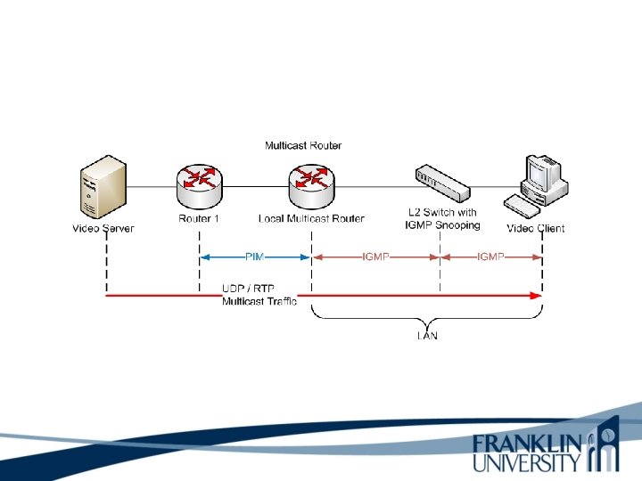
Internet Group Management Protocol (IGMP) • Allows a host to join a multicast group • Host transmits a membership-report message to inform routers on the segment that traffic for a group should be multicast to the host’s segment • IGMPv 2 has support for a router more quickly learning that the last host on a segment has left a group
Multicast Routing Protocols • Becoming obsolete – Multicast OSPF (MOSPF) – Distance Vector Multicast Routing Protocol (DVMRP) • Still used – Protocol Independent Multicast (PIM) • Dense-Mode PIM • Sparse-Mode PIM
Multicast Routing Protocols
Multicast Routing Protocols What is PIM? Protocol-Independent Multicast (PIM) is a family of multicast routing protocol for Internet Protocol (IP) networks that provide one-to-many and many-to-many distribution of data over a LAN, WAN or the Internet. It is termed protocol - independent because PIM does not include its own topology discovery mechanism, but instead uses routing information supplied by other routing protocols.
PIM (Protocol Independent Multicast) What is PIM Dense Mode? • Dense mode is used when there are many members (employees listen to a company president). • Dense PIM does not require the computation of routing tables.
PIM (Protocol Independent Multicast) What is PIM Dense Mode? Dense mode PIM is the older and simpler PIM mode. It works well in small networks where there a large number of listeners, but is inefficient in larger network.
PIM Dense Mode
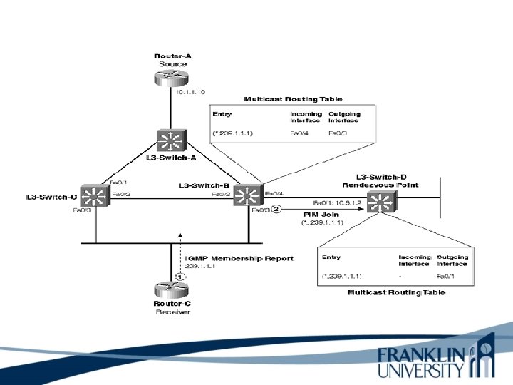
PIM (Protocol Independent Multicast) What is PIM Sparse Mode? • Sparse mode utilizes a rendezvous point (RP). A rendezvous point provides a registration service for a multicast group. • Sparse mode PIM relies on IGMP which let a host join a group by sending a membershipreport message, and detach from a group by sending a leave message.
PIM (Protocol Independent Multicast) What is PIM Sparse Mode? PIM Sparse Mode (PIM-SM) explicitly builds unidirectional shared trees rooted at a rendezvous point (RP) per group, and optionally creates shortest-path trees per source. PIM-SM generally scales fairly well for wide-area usage.
Serialization What is serialization? Serialization is the process of translating data structures or object state into a format that can be stored (for example, in a file or memory buffer, or transmitted across a network connection link) and reconstructed later in the same or another computer environment. When the resulting series of bits is reread according to the serialization format, it can be used to create a semantically identical clone of the original object.
Serialization Delay What is serialization delay? Serialization delay is the time it takes for a unit of data, such as a packet, to be serialized for transmission on a narrow channel such as a cable. Serialization delay is dependent on size, which means that longer packets experience longer delays over a given network path. Serialization delay is also dependent on channel capacity ("bandwidth"), which means that for equalsize packets, the faster the link, the lower the serialization delay.
Reducing Serialization Delay • Link-layer fragmentation and interleaving – Breaks up and reassembles frames – Multilink PPP – Frame Relay FRF. 12 • Compressed Real Time Protocol – RTP is used for voice and video – Compressed RTP compresses the RTP, UDP, and IP header from 40 bytes to 2 to 4 bytes
Reducing Serialization Delay
A Few Technologies for Meeting Qo. S Requirements • • IETF controlled load service IETF guaranteed service IP precedence IP differentiated services
IP Type of Service Field • The type of service field in the IP header is divided into two subfields – The 3 -bit precedence subfield supports eight levels of priority – The 4 -bit type of service subfield supports four types of service • Although IP precedence is still used, the type of service subfield was hardly ever used
IP Type of Service Field Type of Service Subfield Bit 0 3 Precedence 0 D 4 T 8 5 6 R C 7 0 15 D = Delay T = Throughput R = Reliability C = Cost 24 31 Bit Version Header Length Identification Time to Live Total Length Type of Service Flags Protocol Fragment Offset Header Checksum Source IP Address Destination IP Address Options Padding
IP Differentiated Services (DS) Field • RFC 2474 redefines the type of service field as the Differentiated Services (DS) field – Bits 0 through 5 are the Differentiated Services Codepoint (DSCP) subfield • Has essentially the same goal as the precedence subfield • Influences queuing and packet dropping decisions for IP packets at a router output interface – Bits 6 and 7 are the Explicit Congestion Notification (ECN) subfield
IP Differentiated Services (DS) Field 0 6 Differentiated Services Codepoint Explicit Congestion Notification 0 8 Version Header Length 15 Differentiated Services 24 Total Length 31
Resource Reservation Protocol (RSVP) • RSVP complements the IP type-of-service, precedence, DSCP, and traffic-class capabilities inherent in an IP header. • RSVP supports mechanisms for hosts to specify Qo. S requirements for individual traffic flow. • RSVP can be deployed on LANs and enterprise WANs to support multimedia applications or other types of applications with strict Qo. S requirements.
Resource Reservation Protocol (RSVP) • IP header type-of-service capabilities and RSVP are examples of Qo. S signaling protocols.
Classifying LAN Traffic • • IEEE 802. 1 p Classifies traffic at the data-link layer Supports eight classes of service A switch can have a separate queue for each class and service the highest-priority queues first
Cisco Switching Techniques • Process switching is the slowest switching method • Fast switching allows highest throughput by switching a packet using an entry in the fast-cache that was created when a previous packet to the same destination was processed. • Net. Flow switching is optimized for environments where services must be applied to packets to implement security, Qo. S features, and traffic accounting. Example Internet and enterprise network environment boundary.
Cisco Switching Techniques • Cisco Express Forwarding (CEF) is a technique for switching packets quickly across large backbone networks and the Internet. • CEF depended on a forwarding information base (FIB), rather than caching techniques. • FIB allows CEF to use less CPU resources compared to other Layer 3 switching methods. FIB contains forwarding information for all routes in the routing tables.
Cisco Switching Techniques Why did CEF evolve? With the introduction of web-based applications and other interactive applications that are characterized by sessions of short duration to multiple addresses. It became very apparent that the cachebased system could not deliver the needed performance for these applications.
Cisco Queuing Services First in, first out (FIFO) queuing store packets when the network is congested and forward the packets in the order they arrived in when there is no congestion. Disadvantage: No packet priority scheme. Priority queuing ensures that important traffic is processed first. Priority is based on the type of protocol, incoming interface, packet size, and source or destination address. The priorities are high, medium, normal, and low.
Cisco Queuing Services Custom queuing is designed to allow the network to be shared among applications with different minimum bandwidth or latency requirements. Custom queuing provides different amounts of queue space to different protocols and handles the queues in round-robin manner. A particular protocol can be prioritized by assigning it more queue space. Custom queuing can be used to guarantee bandwidth at a potential congestion point.
Cisco Queuing Services Custom queuing helps ensure that each traffic type receives a fixed portion of available bandwidth and that when the link is under stress, no application receives more than a predetermined proportion of capacity. Weighted fair queuing (WFQ) operates from algorithms designed to reduce delay variability and provide predictable throughput and response time for traffic flows. Applications with small payloads are not starved of bandwidth by applications that send large packets.
Cisco Queuing Services Class-based Weighted Fair Queuing (CBWFQ) combines the best scenarios of priority, custom, and weight-fair queuing. Class-based WFQ allows you to define traffic classes based on matching criteria such as protocol, access control lists, and input interfaces. Low latency queuing (LLQ) combines priority queuing with CBWFQ. LLQ brings strict priority queuing to CBWFQ. Strict priority queuing allows delay-sensitive data such as voice to be sent before packets in other queues are sent.
Priority Queuing START Packet in high queue? YES NO Packet in medium queue? YES NO Packet in normal queue? YES NO Packet in low queue? YES Dispatch Packet Continue NO
Custom Queuing START (with Queue 1) NO Packet in Queue? YES Next Queue YES Reached transmission NO window size? Dispatch Packet
Low-Latency Queuing • One queue always gets the green light – Use this for voice • Combine this with class-based weighted fair queuing – Define traffic classes based on protocols, access control lists, and input interfaces – Assign characteristics to classes such as bandwidth required and the maximum number of packets that can be queued for the class
Random Early Detection (RED) • Congestion avoidance rather than congestion management • Monitors traffic loads and randomly discards packets if congestion increases • Source nodes detect dropped packets and slow down – Works best with TCP • Weighted Random Early Detection • Cisco’s implementation uses IP precedence or the DS field instead of just randomly dropping packets
Traffic Shaping • Manage and control network traffic to avoid bottlenecks • Avoid overwhelming a downstream router or link • Reduce outbound traffic for a flow to a configured bit rate Queue bursts of traffic for that flow In summary, traffic shaping is the manipulation and prioritization of network traffic to reduce the impact of heavy users or machines from effecting other users.
Committed Access Rate (CAR) • Cisco feature for classifying and policing traffic on an incoming interface • Supports policies regarding how traffic that exceeds a certain bandwidth allocation should be handled • Can drop a packet or change the IP precedence or DSCP bits
Security Penetration A penetration test is a proactive and authorized attempt to evaluate the security of an IT infrastructure by safely attempting to exploit system vulnerabilities, including OS, service and application flaws, improper configurations, and even risky end-user behavior. Such assessments are also useful in validating the efficacy of defensive mechanisms, as well as end-users’ adherence to security policies.
Security Penetration tests are typically performed using manual or automated technologies to systematically compromise servers, endpoints, web applications, wireless networks, network devices, mobile devices and other potential points of exposure. Once vulnerabilities have been successfully exploited on a particular system, testers may attempt to use the compromised system to launch subsequent exploits at other internal resources, specifically by trying to incrementally achieve higher levels of security clearance and deeper access to electronic assets and information via privilege escalation.
Summary • An untested network design probably won’t work. • It’s often not practical to test the entire design. • However, by using industry testing services and tools, as well as your own testing scripts, you can (and should) test the complex, risky, and key components of a network design.
Summary • Optimization provides the high bandwidth, low delay, and controlled jitter required by many critical business applications • To minimize bandwidth utilization by multimedia applications, use IP multicast • To reduce serialization delay, use link fragmentation and compressed RTP • To support Qo. S and optimize performance, use IP precedence, DSCP, 802. 1 p. advanced switching and queuing methods, RED, CAR, etc.
Review Questions • Why is it important to test your network design? • Why is regression testing important? • What are some characteristics of well-written acceptance criteria? • What are some characteristics of a good network simulation tool?
Review Questions • Why is it important to optimize your network? • What has become of the IP type of service field? • What are some methods for marking packets to identify the need for priority handling? • Compare and contrast Cisco queuing services.
This Week’s Outcomes – Industry Tests – Build and Test a Prototype – Write and Implement a Test Plan – Tools for Testing a Network Design – Multicasting – Qo. S – Queuing and Traffic Shaping
Due this week • 12 -1 – Concept questions 8 • 1 -5 -3 – Network design project – New office network
Next week • Review chapters 12 and 13 in Top-Down Network Design • 13 -1 – Concept questions 9 • 4 -2 -3 – Networking practical experiences – Basic network troubleshooting
Q&A • Questions, comments, concerns?