
Computer Networks and Internets with Internet Applications 4
- Slides: 33
Computer Networks and Internets with Internet Applications, 4 e By Douglas E. Comer Lecture Power. Points By Lami Kaya, LKaya@ieee. org © 2007 Pearson Education Inc. , Upper Saddle River, NJ. All rights reserved.
Chapter 7 Packets Frames and Error Detection © 2007 Pearson Education Inc. , Upper Saddle River, NJ. All rights reserved.
Topics Covered • • • • 7. 1 Introduction 7. 2 The Concept Of Packets 7. 3 Packets And Time-Division Multiplexing 7. 4 Packets And Hardware Frames 7. 5 Byte Stuffing 7. 6 Transmission Errors 7. 7 Parity Bits And Parity Checking 7. 8 Probability, Mathematics, And Error Detection 7. 9 Detecting Errors With Checksums 7. 10 Detecting Errors With Cyclic Redundancy Checks 7. 11 Combining Building Blocks 7. 12 Burst Errors 7. 13 Frame Format And Error Detection Mechanisms © 2007 Pearson Education Inc. , Upper Saddle River, NJ. All rights reserved.
7. 1 Introduction This chapter • describes a fundamental idea in NW • discusses the concept of packets • explains how a sender and receiver coordinate to transfer a packet • shows how packets can be implemented in a characteroriented NW using a simple frame format • explains transmission errors • discusses mechanisms that NW use to detect errors Later chapters expand the packet concept and describe how particular NW technologies handle packets © 2007 Pearson Education Inc. , Upper Saddle River, NJ. All rights reserved.
7. 2 The Concept Of Packets (1) • Most NWs do not send data as continuous streams of bits – NWs divides data into small blocks called packets • Computer NWs are often called packet NW or packetswitching NW because they use packet technology • Two facts motivate the use of packets: – First, a sender and receiver need to coordinate transmission to ensure that data arrives correctly: • Dividing the data into small blocks helps a sender and receiver determine which blocks arrive intact and which do not – Second, communication circuits and the associated modem hardware expensive • multiple computers can share connections and HW to reduce costs © 2007 Pearson Education Inc. , Upper Saddle River, NJ. All rights reserved.
7. 2 The Concept Of Packets (2) Using small packets helps ensure fairness: • To avoid having one computer hold a NW for an arbitrary time, modern NW enforce the use of packets – NW permits one computer to send a packet, then blocks that computer from sending again – Meanwhile the NW permits another computer to send a packet – A single computer can hold a shared resource only long enough to send a single packet – And must wait until other computers have a turn before sending a second packet © 2007 Pearson Education Inc. , Upper Saddle River, NJ. All rights reserved.
© 2007 Pearson Education Inc. , Upper Saddle River, NJ. All rights reserved. 7
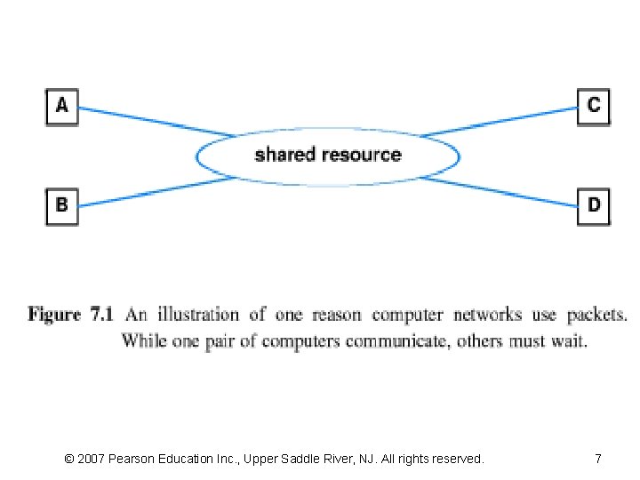
7. 2 The Concept Of Packets (3) How long does a file transfer require? • If a file contains 5 MB and the communication system can transfer 56, 000 bps the transfer will require almost 12 minutes. – Any NW that grants an application exclusive use of shared resources will block other computers for intolerably long periods of time • In contrast, consider the delays introduced when the NW in Figure 7. 1 requires computers to divide data into packets that each contain 1000 bytes of data: – – Suppose computer A begins sending data to D after A begins sending, computer B needs to send data to C After A finishes sending one packet, the NW will allow B to send one because a packet contains only 8000 bits (1000 x 8) of data and the transfer rate 56, 000 bps, a complete packet can be sent in only 0. 143 s © 2007 Pearson Education Inc. , Upper Saddle River, NJ. All rights reserved.
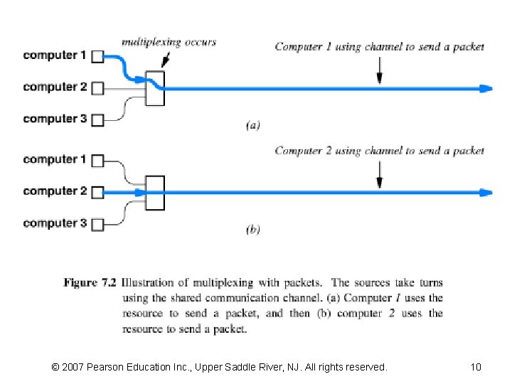
7. 3 Packets And Time-Division Multiplexing • Conceptually, a NW that permits many sources to take turns accessing a shared resource – providing a form of time-division multiplexing (TDM) – Figure 7. 2 illustrates the idea • Dividing data into small packets ensures that all sources receive prompt service – because it prohibits one source from gaining exclusive access for an arbitrarily long time • Allowing sources to take turns sending packets guarantees – that a source with a small amount of data will finish promptly © 2007 Pearson Education Inc. , Upper Saddle River, NJ. All rights reserved.
© 2007 Pearson Education Inc. , Upper Saddle River, NJ. All rights reserved. 10
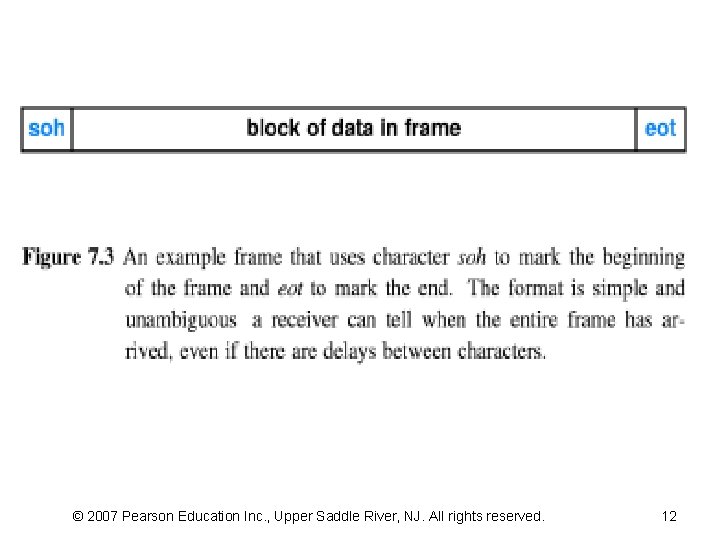
7. 4 Packets And Hardware Frames • No universal agreement on the exact format of a packet • Instead, each HW technology defines the details of packets and specifies how individual bits of the packet are transmitted – “frame” is a packet used with a NW • the sender and receiver must agree on – how they will specify the beginning and end of each frame • ASCII includes codes for unprintable characters: – We can use two of the unprintable ASCII characters to delimit a frame • Figure 7. 3 illustrates a frame • The example framing scheme has disadvantages and advantages: – The chief disadvantage is overhead – The chief advantage is handling system failures and reboots © 2007 Pearson Education Inc. , Upper Saddle River, NJ. All rights reserved.
© 2007 Pearson Education Inc. , Upper Saddle River, NJ. All rights reserved. 12
7. 5 Byte Stuffing (1) • NW permits an application to transfer arbitrary characters • An application may choose to send data that contains one or more occurrences of characters like soh and eot • Transmitting such characters in the data portion of a frame causes problems – an eot to mean that the entire frame has arrived – an soh to mean a new frame has started to arrive • Insert extra bits or bytes to change data for transmission, – the technique is known as “data stuffing” – “byte stuffing” and “character stuffing” refer to data stuffing used with character-oriented – “bit stuffing” refers to data stuffing used with bit-oriented © 2007 Pearson Education Inc. , Upper Saddle River, NJ. All rights reserved.
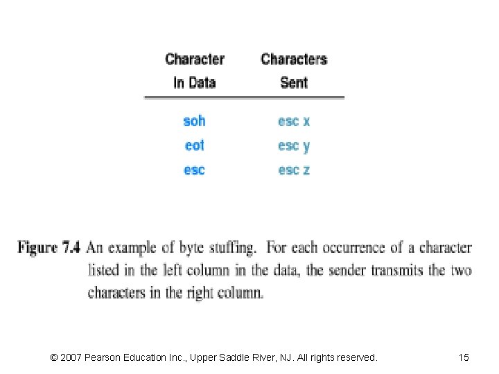
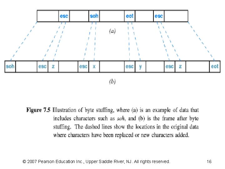
7. 5 Byte Stuffing (2) • Byte stuffing can solve the problem – by reserving a third character to mark occurrences of reserved characters in the data – Suppose the ASCII character esc (Hex =1 Bh ) has been selected as the third character • When any of the three special characters occur in data – the sender inserts esc and replaces the character • Figure 7. 4 summarizes the mapping • Figure 7. 5 shows an example data block and the resulting frame after byte stuffing has occurred © 2007 Pearson Education Inc. , Upper Saddle River, NJ. All rights reserved.
© 2007 Pearson Education Inc. , Upper Saddle River, NJ. All rights reserved. 15
© 2007 Pearson Education Inc. , Upper Saddle River, NJ. All rights reserved. 16
7. 6 Transmission Errors • Lightning, power surges, and other EM interference – can introduce unwanted electrical currents • A small change in the electrical signal can – cause the receiver to misinterpret one or more bits of the data • Interference can – – cause permanent damage to NW equipment (lightening) changes the signal completely destroy a signal create the opposite effect • although the sender does not transmit anything, a receiver might interpret the incoming interference as a valid sequence © 2007 Pearson Education Inc. , Upper Saddle River, NJ. All rights reserved.
7. 7 Parity Bits And Parity Checking (1) • Fortunately, new communication systems do not experience frequent interference – local communication circuits often operate for years without serious problems – on a long-distance communication circuit may be so small that modems can handle all problems automatically • Despite the low probability of error – we should provide HW and SW mechanisms to detect and correct such problems © 2007 Pearson Education Inc. , Upper Saddle River, NJ. All rights reserved.
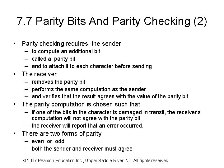
7. 7 Parity Bits And Parity Checking (2) • Parity checking requires the sender – to compute an additional bit – called a parity bit – and to attach it to each character before sending • The receiver – removes the parity bit – performs the same computation as the sender – and verifies that the result agrees with the value of the parity bit • The parity computation is chosen such that – if one of the bits in the character is damaged in transit, the receiver's computation will not agree with the parity bit – the receiver will report that an error occurred. • There are two forms of parity – even or odd – both the sender and receiver must agree © 2007 Pearson Education Inc. , Upper Saddle River, NJ. All rights reserved.
7. 8 Probability, Mathematics, And Error Detection • Parity mechanism discussed above – works well to detect a single bit error, – but it cannot detect all possible errors • There are several alternatives – In each mechanism, the sender transmits additional information along with the data – and the receiver uses the information to verify • Differences among the mechanisms arise in three ways: – the size of the additional information – the computational complexity of the algorithm – and the number of bit errors that can be detected © 2007 Pearson Education Inc. , Upper Saddle River, NJ. All rights reserved.
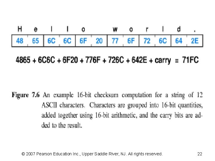
7. 9 Detecting Errors With Checksums (1) • Many NW systems send a checksum along with each packet to help the receiver detect errors • To compute a checksum – the sender treats the data as a sequence of binary integers and computes their sum – The data is not restricted to integer values • it can contain characters, floating point numbers, or an image – The network system merely treats the data as a sequence of integers for purposes of computing a checksum • Figure 7. 6 illustrates a 16 -bit checksum computation • The sender – treats each pair of characters as a 16 -bit integer – it computes the sum • If the sum grows larger than 16 bits, the carry bits are added into the final sum © 2007 Pearson Education Inc. , Upper Saddle River, NJ. All rights reserved.
© 2007 Pearson Education Inc. , Upper Saddle River, NJ. All rights reserved. 22
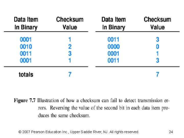
7. 9 Detecting Errors With Checksums (2) • The chief advantages arise from the size and ease of computation. – Most NW that employ a 16 -bit or 32 -bit checksum – compute a single checksum for an entire packet • The small size of the checksum means – the cost of transmitting the checksum is usually much smaller than the cost of transmitting the data – the computation required to create or verify a checksum is small • Checksums have the disadvantage of not detecting all common errors • Figure 7. 7 shows that a checksum is not sufficient to detect a transmission error that reverses a bit in each of four data items – Despite the changes, a receiver will declare that the packet has a valid checksum – Reversing the value of the second bit in each data item produces the same checksum © 2007 Pearson Education Inc. , Upper Saddle River, NJ. All rights reserved.
© 2007 Pearson Education Inc. , Upper Saddle River, NJ. All rights reserved. 24
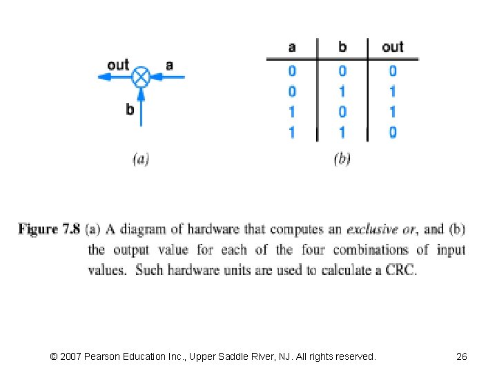
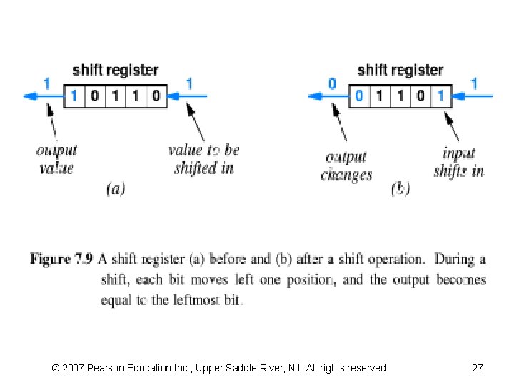
7. 10 Detecting Errors With Cyclic Redundancy Checks • How can a NW detect more errors without increasing the amount of additional information in each packet? – The answer lies in Cyclic Redundancy Check (CRC) techniques • CRC techniques are also used to verify that data has been recorded correctly on storage devices – such as magnetic disks • Figure 7. 8 shows some HW components • Figure 7. 9 illustrates how bit values move during a shift operation and how the output changes © 2007 Pearson Education Inc. , Upper Saddle River, NJ. All rights reserved.
© 2007 Pearson Education Inc. , Upper Saddle River, NJ. All rights reserved. 26
© 2007 Pearson Education Inc. , Upper Saddle River, NJ. All rights reserved. 27
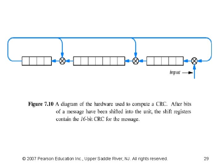
7. 11 Combining Building Blocks (1) • Figure 7. 10 illustrates how to compute a 16 -bit CRC • Several CRC algorithms exist – the algorithms differ in the number of bits allocated to each of the three shift registers and the initial values used • Instead of computing a CRC over the incoming message and then comparing it to the incoming CRC – the receiver computes a CRC over the incoming message plus the incoming CRC – If all bits are received correctly, the computed value will be zero © 2007 Pearson Education Inc. , Upper Saddle River, NJ. All rights reserved.
© 2007 Pearson Education Inc. , Upper Saddle River, NJ. All rights reserved. 29
7. 11 Combining Building Blocks (2) There are two reasons a CRC can detect more errors than a simple checksum • First, because an input bit is shifted through all three registers, – a single bit of the message affects the resulting CRC in dramatic ways • Second, because the hardware uses feedback in which the output from the leftmost shift register affects each exclusive or unit – the effect from a single bit of the message cycles through the shift registers more than one time • Mathematically, a CRC uses a polynomial, usually expressed as powers of polynomial, to divide the message © 2007 Pearson Education Inc. , Upper Saddle River, NJ. All rights reserved.
7. 12 Burst Errors Two case where is CRC especially • First, HW failures sometimes cause a specific set of bits to be damaged – Ex, a character-oriented I/O device that is damaged might set the first two bits of every character to zero – Such errors are sometimes called vertical errors • because they appear in a vertical column when the characters are arranged in rows • Second, CRCs are especially useful for detecting errors that involve changes to a set of bits – called error “burst errors” • interference may be caused by lightning, starting of an electric motor, etc © 2007 Pearson Education Inc. , Upper Saddle River, NJ. All rights reserved.
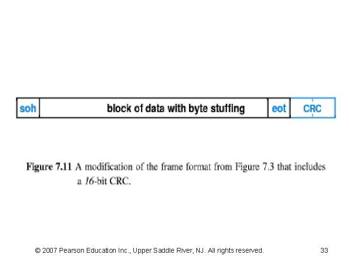
7. 13 Frame Format And Error Detection Mechanisms • NW usually associate error detection information with each frame – The sender calculates information such as a checksum or CRC – The receiver calculates the same value and compares it to the additional information that arrives in the frame • Figure 7. 11 illustrates a simple frame format • Is byte stuffing required for the CRC as well? – The answer depends on the types of error detection required • If characters can be lost, byte stuffing the CRC can add reliability © 2007 Pearson Education Inc. , Upper Saddle River, NJ. All rights reserved.
© 2007 Pearson Education Inc. , Upper Saddle River, NJ. All rights reserved. 33