INDUSTRIAL FAN Fan AMCA Air Movement Control Association


 & Medium Flow High pressure")


& High Flow Applications HVAC Higher")

& Medium flow Applications High pressure application Higher")


*Δp(static pr. rise)mmwc*100 102*Shaft Input")


- Slides: 40
INDUSTRIAL FAN
Fan �AMCA - Air Movement & Control Association AMCA is international association of the world’s manufacturers air system equipment – fans, louvers, dampers, air curtains, airflow measurement stations and other air system components for industrial, commercial and residential markets. People who buy and specify fans, dampers, and louvers need to be aware of the value of the AMCA International seal. �Fan is a volumetric flow machine which increases pressure energy of gaseous medium by rotational motion of blades mounted on disc (known as impeller). �Working Principle-This rotational motion of blades imparts enough energy to medium which set it into motion against low pressure & overcome all resistances (whatever comes in its path) to flow.
Fan • Air/gas sucked into the fan and gets pressurized between consecutive blades. • Impeller imparts energy through rotational and centrifugal action and impels the flow out of its periphery. • Involute shaped casing collects cumulative angular flow coming out from impeller periphery and leads towards outlet.
Main Requirement of Fan �Basic difference between Fan, Blower & Compressor: Specific Ratio Pressure Rise (mmwc) Fan Up to 1. 11 1136 Blower 1. 11 ~ 1. 2 1136 ~ 2066 Compressor >1. 2 - Specific Ratio i. e. Pressure ratio = Absolute Pr. at outlet = Pa+Po Absolute Pr. at inlet Pa-Pi where, Pa = Atmospheric Pressure Pi = Fan Suction Pressure Po = Fan Discharge Pressure
Types of Fan Centrifugal Forward Curve Straight Radial Blade Axial Backward Curve Radial Tip Propeller Tube Axial Vane Axial
Types of Fans classification on basis of flow direction: �Centrifugal Fan : If air moves perpendicular to the rotational axis of impeller. Shaft Impeller �Axial Fan : If air moves parallel to the rotational axis of impeller.
Centrifugal v/s Axial Centrifugal Axial Capable of generating high pressure with high efficiency Ability to generate reverse airflow Capable to serve at wide varying operating condition Unsuitable to serve in wide varying operating condition due to several stall* region (In stall region, air flow is insufficient to fill the blades causing fan to operate in unstable condition. ) Large in size Compactness Heavy & Bulky Light weight Moderate speed for same volume Faster at same air flow capacity Expensive Low cost More power consumption Less power consumption
Centrifugal Fan � Classification on basis of blade types i. e. angle between the blade tip & direction of rotation known as blade angle. � Forward Curve Straight Backward Curve <90 Va Vab Vb Va – Air Velocity blade 90 Va >90 Vab Vb Vb – Blade Tip Velocity Va Vab Vb Vab – Air velocity relative to Produce High Velocity Medium Velocity Low Velocity That’s why, backward curved blade type operates at greater motor speeds to get same Vab.
Forward-Curved Fan Characteristics Medium Pressure & High Flow Applications Low pressure HVAC Best suited for moving large volume of air against relatively low pressure due to low blade tip speed Packaged Units Low Efficiency 60 -65% Suitable for clean environments and operate at lower temperatures
Forward. Curved Fan • Dip in pressure curve(represents a stall region that create operating problem at low airflow rates) • Power rises continuously
Radial Blade Fan Characteristics Applications High Static Pressure(140 mmwc) & Medium Flow High pressure HVAC Best suited for moving low to medium volume of air against relatively high pressure due to medium blade tip speed Due to this, it is well suited for higher Simple Design temperatures and medium blade tip speeds Due to this, capable of handling highparticulate airstreams(like dust, wood, chips, metal chips, laden, moist Flat Blade shape limits material build-up air/gases) More Durability due to large clearance between blades which allow this fan to operate at low airflow rates without vibration problem that usually occur due to operating in stall region. Average Efficiency 69 -75%
Radial-Tip Fan Characteristics Applications Fills the fan requirement gap between clean -air fans and more rugged radial-blade fans Low Turbulence due to low angle of attack between the blades and incoming air Large running clearance Efficiency up to 79% Due to this, they are used in airborne-solids (airstream that have small particulates at moderate concentration)handling services and high moisture contents
Backward-Curved Fan Characteristics Applications High Pressure & High Flow HVAC Also known as Non-overloading because change in static pressure do not overload the motor Forced Draft service fan High Blade tip speed 3 different blade shapes: Flat(more robust), Curved (more efficient), Aerofoil(most efficient-85%) As aerofoil blades rely on the lift created by each blade which is highly susceptible to unstable operation because of stall. But due to backward curve orientation, there is low angle of impingement with airstream which promotes the accumulation of particulates on fan blades. Thin aerofoil blades are more efficient than other blade types because of lower rotating mass. But this thin walled characteristics makes fan Due to this, It's mainly application for clean-air highly susceptible to erosion problems stream High Efficiency 85% Due to high efficiency, it provide low system life cycle cost
Backward. Curved Fan • As flow increases, power increases. But at high airflow rates, it drops off due to non-overloading characteristics. • Due to this, it's often selected when system behaviour at high airflow rates is uncertain.
Centrifugal Fans
Efficiency Curve
Axial Fan Axial fan - Air moves along the axis of an impeller. �Working Principle - Axial fans consists of an impeller on the periphery of which the blades are mounted. The impeller draws the medium from a suction chamber, imparts energy and discharge it into diffuser. At outlet of diffuser, kinetic energy is converted into potential energy and the necessary head is obtained. �Three types of Axial Fan: -- Propeller fan -- Tube-axial fan -- Vane-axial fan
Propeller Fan Characteristics Applications Low pressure & High flow due to there is large change in air flow with small change in static pressure Ventilation , Exhaust fan Outdoor application like ACC , Cooling Low efficiency - 45 to 50% Tower Peak efficiency close to point of free air delivery(zero static pressure) Run at low speeds and moderate temperature Noisy Inexpensive because of simplest construction Due to this often used in roof top ventilation
Propeller Fan • Power requirement decreases with increase in air flow rates • More Unstable region
Tube Axial Fan Characteristics Medium Pressure (250 -400 mmwc)& High Flow Applications HVAC Higher Efficiency (67 -72%) than Propeller due to improving air flow characteristics by placing propeller inside a cylinder Drying Ovens Moderate Noise Exhaust System application because it create sufficient pressure to overcome duct loss & space efficient also Less in weight Ventilation application due to low rotating mass & quickly accelerate to operating rated speed
Tube-Axial fan • Instability region: Dip in pressure-flow curve before peak pressure point • Moderate unstable region
Vane-Axial Fan Characteristics High pressure (500 mmwc)& Medium flow Applications High pressure application Higher Efficiency (78 -85%) than Tube-axial due to more improving air flow pattern by placing tube-axial fan with outlet vanes i. e. guide vanes (outlet vanes create uniform air flow profile & also convert KE to PE) HVAC , Exhaust System Light in weight (low rotating mass) & quickly Emergency Ventilation application where accelerate to relative operating rated speed quick air supply or removal is required Also generate flow in reverse direction Variable pitch blades equipped which adjust to change the angle of attack of incoming airstream Due to this, supply of fresh air or removal of contaminated air
Vane-Axial Fan • Instability region: Dip in pressure-flow curve left of peak pressure point • Less unstable region
Fan Pressure Relationship �Static Pressure – Pressure exerted on a wall by the adjacent fluid which is at rest or which is flowing without disturbance along the wall of conduit. �Velocity Pressure- Pressure equivalent of the velocity at which fluid is flowing. �Total Pressure – Pressure of fluid in motion is the total pressure which is algebraic sun of velocity pressure and static pressure. � TP=SP+VP �Fan Total Pressure – Pressure that exists by virtue of compression and the rate motion i. e. the total pressure difference at outlet and inlet of fan.
Fan Pressure Relationship �Fan Velocity Pressure – Pressure corresponding to the average velocity at the specified fan outlet area i. e. Velocity pressure at outlet. �Fan Static Pressure = Fan total pr. – Fan Velocity Pr. Or =Static pr. at outlet – Total pr. at inlet of fan �Static Pressure Rise =Difference of Static Pr. At outlet and inlet of fan.
Pressure Measurement
Fan Efficiency � Power imparted to airstream wrt to power delivered to the motor � Fan Efficiency = Fan Power(i. e. flow*pressure rise) Power Input(i. e. Shaft Power) • Fan Total Eff. Or Fan Mech. Eff. • Fan Static Eff.
Fan Efficiency �Fan Static Eff. : ηstatic=vol. (m 3/sec. )*Δp(static pr. rise)mmwc*100 102*Shaft Input Power(k. W) Where, Q=area*velocity Velocity=0. 88*sqrt(2*g*dynamic pr. /density) Density=1. 293*273/(273+temp. )*(9780. 4+Static pr. )/10336
Fan Affinity Law
System Resistance • System Resistance is the sum of static pressure losses in the system. • The system resistance is a function of the configuration of ducts, pickups, elbows and the pressure drops across equipment. • The system resistance varies with the square of the volume of air flowing through the Governing Equation for pressure loss across system. any particular component is: i. e. SR α Q 2. ΔP=k. ρ. Q 2
System Resistance Ex. Q P 1 ΔP P 2 Mass flow rate = ρQ Volume flow rate = Q ΔP = k. ρQ. Q = k. ρQ 2 (Parabolic Curve) where, k=constant characteristics of loss coefficient for the component ρ=density of airstream Q=volume flow of the airstream Thus, the system resistance i. e. Pressure increases substantially as the volume of air flowing through the system increases; square of air flow.
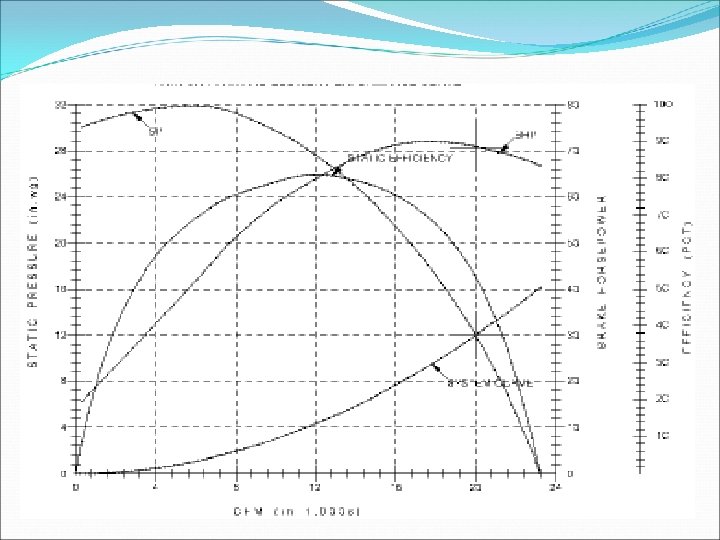
Fan Characteristics �The intersection of the system curve and the static pressure curve defines the operating point. � When the system resistance changes, the operating point also changes. � Once the operating point is fixed, the power(BHP) required could be found.
System Characteristics & Fan Curve �To reduce air flow from Q 1 to Q 2 �Thus, reducing the fan speed is a much more efficient method to decrease airflow since less power is required and less energy is consumed.
Iso-Efficiency Curve
Series & Parallel Fan
Instability Region
Surge or Stall Limit �Surge Limit- The surge limit of a centrifugal fan is that point near the peak of the pressure curve corresponding to minimum flow rate at which the fan can be operated without instability. �Stall Limit- The stall limit of an axial fan is that point near the peak of the pressure curve at a particular blade angle corresponding to minimum flow rate at which the fan can be operated without separation airflow over the blades. Stall occurs when angle of attack of fan blade (or aero plane wing) exceeds a certain value in relationship to air velocity. �Fan must not be operated in the surge or stall region, serious damage can occur
Surge or Stall limit
Thank You