Chapter 4 Pneumatic System Single Actuator Circuit Prepared


 This type of circuit is")


")
 is pressed, the")


- Slides: 38
Chapter 4 Pneumatic System: Single Actuator Circuit Prepared by: Mohd Shahril bin Shariff
Pneumatic Circuit • Pneumatic control systems can be designed in the form of pneumatic circuits. A pneumatic circuit is formed by various pneumatic components, such as cylinders, directional control valves, flow control valves, pressure regulator, signal processing elements such as shuttle valve, two pressure valve etc. Pneumatic circuits have the following functions: ü To control the entry and exit of compressed air in the cylinders. ü To use one valve to control another valve ü To control actuators or any other pneumatic devices
DIRECT CONTROL OF SINGLE ACTING CYLINDER The simplest level of control for the single or doubleacting cylinder involves direct control signal. With this, the cylinder is actuated directly via a manually or mechanically actuated valve, without any intermediate switching of additional directional control valve Reference value for limits of direct cylinder control: §Cylinder with piston diameter smaller than 40 mm §Valve with connection sizes smaller than 1/4"
DIRECT CONTROL OF SINGLE ACTING CYLINDER When the directional control valve is actuated by push button, the valve switches over to the open position, communicating working source to the cylinder volume. This results in the forward motion of the piston. When the push button is released, the reset spring of the valve restores the valve to the initial position [closed]. The cylinder space is connected to exhaust port there by piston retracts either due to spring or supply pressure applied from the other port.
Example 1 A small single acting cylinder is to extend and clamp a work piece when a push button is pressed. As long as the push button is activated, the cylinder should remain in the clamped position. If the push button is released, the clamp is to retract. Use additional start button. Schematic diagram of the setup is shown in Figure
Solution Example 1 The control valve used for the single acting cylinder is the 3/2 way valve. In this case, since the cylinder is of small capacity, the operation can be directly controlled by a push button 3/2 way directional control valve with spring return. When start button and 3/2 NC valve is operated, cylinder moves forward to clamp the work piece. When start button and 3/2 way valve is released cylinder comes back to the retracted position as shown in the figure above.
Example 2 A city-centre car park has a barrier system to prevent people parking illegally. The car park attendant checks all the cars entering and leaving the car park. The barrier is raised and lowered by a single-acting cylinder. The attendant pushes a button to operate the system.
Solution Example 2 When the button is pressed, the valve changes state and supplies air to the singleacting cylinder. This causes the piston to outstroke with enough force to raise the barrier.
INDIRECT CONTROL OF SINGLE ACTING CYLINDER (single pilot operated) This type of circuit is suitable for large single cylinders as well as cylinders operating at high speeds. The final pilot control valve is actuated by normally closed 3/2 push button operated valve. The final control valves handle large quantity of air. When the push button is pressed, 3/2 normally closed valve generate a pilot signal 12 which controls the final valve thereby connecting the working medium to piston side of the cylinder so as to advance the cylinder. When the push button is released, pilot air from final valve is vented to atmosphere through 3/2 NC – DCV. The signal pressure required can be around 1 -1. 5 bar. The working pressure passing through the final control valve depends on the force requirement which will be around 4 -6 bar. Indirect control as permits processing of input signals. Single pilot operated valves are rarely used in applications where the piston has to retract immediately on taking out the set pilot signal.
Example 3 A large single acting cylinder is to extend and clamp a work piece when a push button is pressed. As long as the push button is activated, the cylinder should remain in the clamped position. If the push button is released, the clamp is to retract. Use additional start button.
Solution Example 3 The control valve used for the single acting cylinder is the 3/2 way valve. In this case, since the cylinder is of large capacity, the operation cannot be directly controlled by a push button 3/2 way directional control valve with spring return. Indirect control is to be used as shown in the figure. Valve 2 is a small capacity valve which controls the large capacity valve 3. When the valve 2 is unactuated the cylinder is in the retracted condition. When the valve 2 is actuated the cylinder is in the extended position to clamp the work piece.
CONTROL OF SINGLE ACTING CYLINDER USING “OR” VALVE Shuttle valve is also known as double control valve or double check valve. A shuttle valve has two inlets and one outlet (Figure below). At any one time, flow is shut off in the direction of whichever inlet is unloaded and is open from the loaded inlet to the outlet. This valve is also called an OR valve. A shuttle valve may be installed for example, when the cylinder or valve is to be actuated from two points, which may be remote from one another. The single acting cylinder in the figure can be operated by two different circuits. Examples include manual operation and relying on automatic circuit signals, that is, when either control valve 1 or control valve 2 is operated, the cylinder will work. Therefore, the circuit in the figure possesses the OR function.
CONTROL OF SINGLE ACTING CYLINDER USING “AND” VALVE This valve is the pneumatic AND valve. It is also derivate of Non Return Valve. A two pressure valve requires two pressurised inputs to allow an output from itself. The cross sectional views of two pressure valve in two positions are given in the figure. As shown in the figure, this valve has two inputs 12 and 14 and one output 2. If the compressed air is applied to either 12 or input 14, the spool moves to block the flow, and no signal appears at output 2. If signals are applied to both the inputs 12 and 14, the compressed air flows through the valve, and the signal appears at output 2.
Another name for an AND function is interlock control. This means control is possible only when two conditions are satisfied. A classic example is a pneumatic system that works only when its safety door is closed and its manual control valve is operated. The flow passage will open only when both control valves are operated. Figure shows the circuit diagram of an AND function circuit. The cylinder will work only when both valve 1 and 2 are operated.
DIRECT CONTROL OF DOUBLE ACTING CYLINDER The only difference between a single acting cylinder and a double acting cylinder is that a double acting cylinder uses a 5/2 directional control valve instead of a 3/2 directional control valve. Usually, when a double acting cylinder is not operated, outlet ‘B’ and inlet ‘P’ will be connected. In this circuit, whenever the operation button is pushed manually, the double acting cylinder will move back and forth once In order to control the speed in both directions, flow control valves are connected to the inlets on both sides of the cylinder. The direction of the flow control valve is opposite to that of the release of air by the flow control valve of the single acting cylinder. Compared to the throttle inlet, the flow control valve is tougher and more stable. Connecting the circuit in this way allows the input of sufficient air pressure and energy to drive the piston.
Example 4 A city-centre car park has a barrier system to prevent people parking illegally. The car park attendant checks all the cars entering and leaving the car park. The barrier is raised and lowered by a double-acting cylinder. The attendant pushes a button to operate the system.
Solution Example 4 When the attendant actuates valve A by pressing the button, the double-acting cylinder outstrokes and lifts the barrier. It stays in this position until valve B is actuated. This allows the piston to instroke and the barrier is lowered.
IN DIRECT CONTROL OF DOUBLE ACTING CYLINDER USING MEMORY VALVE(Double pilot operated)
When the 3/2 way valve meant for Forward motion (Figure b) is pressed, the 5/2 memory valve switches over through the signal applied to its pilot port 14. The piston travels out and remains in the forward end position. Double piloted valve is also called as the Memory valve because now even if this push button meant Forward is released the final 5/2 control valve remains in the actuated status as the both the pilot ports of 5/2 valves are exposed to the atmosphere pressure and the piston remains in the forward end position. When the 3/2 way valve meant for return motion (Figure a) is pressed, the 5/2 way valve switches back to initial position through the signal applied to its pilot port 12. The piston then returns to its initial position and remains in the rear end position. Now even if the Return push button is released the status of the cylinder will not change. The circuit is called a memory circuit because it uses a 5/2 way double pilot memory valve. 5/2 way valve can remember the last signal applied in terms of the position of the spool in the absence of reset springs, thus memorising or storing the pneumatic signal. Double piloted 4/2 way valve also can be used as memory valve
Example 5 Pneumatic system is to be designed to operate a door of public transport vehicles. Assuming that the opening and closing of the doors are controlled by two button switches ON and OFF. When the button switch ON is pressed, the door will open. When the button switch OFF is pushed, the doors will close.
Solution Example 5
Example 6 A city-centre car park has a barrier system to prevent people parking illegally. The car park attendant checks all the cars entering and leaving the car park. The barrier is raised and lowered by a double-acting cylinder. The attendant pushes a button to operate the system. The attendant has complained that the barrier rises to quickly and is worried that this may damage it. Suggest a circuit to solve the problem.
Solution Example 6 The restrictor is placed so that it slows down the exhaust air coming from the cylinder. When valve A is pressed, the 5/2 valve changes state and starts to supply the cylinder with air to make it outstroke. Air trapped on the other side of the piston escapes through the restrictor slowly. This makes the piston outstroke slowly. Always restrict the exhaust air coming from a cylinder as this makes the piston move much more smoothly.
SUPPLY AIR THROTTLING AND EXHAUST AIR THROTTLING It is always necessary to reduce the speed of cylinder from maximum speed based on selected size of final control valve to the nominal speed depending on the application. Speed control of Pneumatic Cylinders can be conveniently achieved by regulating the flow rate supply or exhaust air. The volume flow rate of air can be controlled by using flow control valves which can be either two way flow control valve or one way flow control valve There are two types of throttling circuits for double acting cylinders: i) Supply air throttling ii) Exhaust air throttling
A. Supply air throttling This method of speed control of double acting cylinders is also called meter –in circuit (Figure). For supply air throttling, one way flow control valves are installed so that air entering the cylinder is throttled. The exhaust air can escape freely through the check valve of the throttle valve on the outlet side of the cylinder. There is no air cushion on the exhaust side of the cylinder piston with this throttling arrangement. As a result, considerable differences in stroking velocity may be obtained even with very small variations of load on the piston rod. Any load in the direction of operating motion will accelerate the piston above the set velocity. Therefore supply air throttling can be used for single acting and small volume cylinders.
B. Exhaust air throttling This method of speed control of double acting cylinders is also called meter-out (Figure). In exhaust air throttling throttle relief valves are installed between the cylinder and the main valve in such a way that the exhaust air leaving the cylinder is throttled in both directions of the motion of the cylinder. The supply air can pass freely through the corresponding check valves in each case. In this case, the piston is loaded between two cushions of air while the cylinder is in motion and hence a smooth motion of the cylinder can be obtained. The first cushion effect is due to supply air entering the cylinder through check valve, and second cushion effect is due to the exhaust air leaving the cylinder through the throttle valve at a slower rate. Therefore, exhaust air throttling is practically used for the speed control of double acting cylinders. Arranging throttle valves in this way contributes substantially to the improvement of feed behaviour.
VARIOUS METHODS OF CHECKING END POSITION OF A CYLINDER The following methods are commonly used to know the end positions of piston in the cylinder: a) Mechanically operated limit switches i) Roller lever type ii) Idle return roller type b) Reed sensors – Normally used in cylinder with magnetically coupled slide i) With Electrical output ii) With pneumatic output c) Electrical proximity switches d) Pneumatic Signal generators
A. Use of Limit Switches
S 1 and S 2 are the limit switches corresponding to home position and extended position. Although they are located in the path of the movement of piston rod, normal practice is to represent the symbol of the limit switches on either side of the 3/2 way control valve without put signals connected to the pilot ports of the valve. ( in this Figure pilot signals actuations are shown for clarity) The limit switches of Roller lever type are essentially 3/2 way ball seat or disc seat type of valves handling pneumatic signals. These are available with direct actuation type and internally pilot actuation type versions. Limit switches of idle return roller type are used for actuation only in one direction are used as signal elimination device in case of signal overlap.
PRESSURE DEPENDENT CONTROLS Sequence Valve generates a pneumatic signal if the sensing pressure [signal input] is more than the desired set pressure. This generated output signal is used to control the movement of cylinder by using it as a set signal or reset signal to the final control valve to obtain forward or return motion respectively. Used for applications such as bonding cylinders, clamping cylinder etc. to ensure desired minimum pressure in the cylinder. This is a combination valve, having two sections. One of the section is a 3/2 directional control and the other a pressure control valve. Example 7: A double acting cylinder is used to press together glued components (Estimated pressure is around 4 bar). Upon pressing a push button, the clamping cylinder is to extend and trip the roller valve. One the fully extended position of the cylinder has been reached and sufficient clamping force has been developed, the cylinder is to retract to the initial position, develop a pneumatic circuit using a pressure sequence valve.
Solution Example 7
The two position of the pneumatic circuit for the control task, when the cylinder is extending and when the cylinder is fully extended, are shown in Figure. The pressure in the sequence valve is set to working pressure of 4 bar, and the signal input to the pressure sequence valve is tapped from the power line from port 4 of valve 1. 1 to the cylinder to gauge the pressure on the piston side of the cylinder. As shown in the Figure valve 1. 2 initiates the forward motion of the cylinder. While the cylinder is moving forward, the pressure in the power line from port 4 of valve 1. 1 to the cylinder will not built up to the working pressure. Only after the cylinder is fully extended, will the maximum pressure in the line built up resulting in sufficient pressure to glue. When the set pressure in the sequence valve is reached, the integrated 3/2 directional control valve is actuated, generating an output signal. This signal is used to reset the final control element 1. 1 and thus causing the return motion of the cylinder.
TIME DEPENDENT CONTROLS Pneumatic timers are used to create time delay of signals in pilot operated circuits. Available as normally closed timers and normally open timers. Usually pneumatic timers are on delay timers. Time delay valve is a combination of a pneumatically actuated 3/2 direction control valve, an air reservoir/accumulator and a one way flow control valve. The time delay function is obtained by controlling the air flow rate to or from the reservoir by using the throttle valve. Adjustment of throttle valve permits fine control of time delay between minimum and maximum times. In pneumatic time delay valves, typical time delays in the range 5 -30 seconds are possible. The time delay can be extended with the addition of external reservoir/accumulator.
In on-delay timer, the 3/2 DCV is actuated after a delay with reference to the application of pilot signal and is rest immediately on the application of the pilot signal. In off delay timer, the 3/2 DCV is actuated immediately on the application of the pilot signal and is reset only after a delay with reference to the release of the pilot signal.
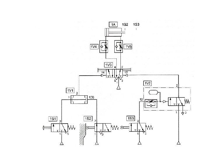
Example 8 A double-acting cylinder is used to press together glued components. Upon operation of a push button, the clamping cylinder extends slowly. Once the fully advanced position is reached, the cylinder is to remain for a time T=6 seconds and then immediately retract to the initial position. The cylinder retraction is to be adjustable. A new start cycle is only possible after the cylinder is fully retracted.
Solution Example 8