2018 Air Movement Control Association Inc All Association


 747 Pa (duct design) E")

 747 Pa (duct design) D")

 NC N H H,")


- Slides: 56
© 2018 - Air Movement & Control Association Inc. All Association. Rights Reserved © 2017 Air International, Movement and Control All Rights Reserved.
Copyright Materials This educational activity is protected by U. S. and International copyright laws. Reproduction, distribution, display, and use of the educational activity without written permission of the presenter is prohibited. © AMCA International 2
Learning Objectives • Definition of System Effect • How to calculate System Effect • System Effect’s effect on power consumption • The difference between inlet and outlet System Effect • How to avoid System Effect 2
Efficiency, η Fan Efficiency Air Flow, Q 3
Regulation 3– 5% Efficiency, η 76 million ton 2 of coal Air Flow, Q 4
Efficiency, η What we can do Air Flow, Q 5
What we can do Efficiency, η 25 - 40 % Air Flow, Q 6
Fan Testing for Air Performance 7
AMCA Standard 210 Piezometer Ring Fan Static Pressure Test Fan Nozzles Fan Airflow Auxiliary Fan 8
Nozzle Wall 9
AMCA 210 Test Results 800 2. 5 700 2 500 1. 5 400 1 300 200 Power, H Pressure, P 600 0. 5 100 0 2 4 6 8 10 12 Air Flow, Q 10
AMCA Standards 500 -D & -L Test Damper Piezometer Ring Damper Pressure Drop Nozzles Damper Airflow Auxiliary Fan 11
Fan Operating Point 700 AMCA 500 -D Test Results 600 500 Pressure, P Operating Point 400 300 200 100 0 0 2 4 6 Air Flow, Q 8 10 12 12
Speed Change 800 700 600 New Operating Point Pressure, P 500 New speed Operating Point 400 300 200 100 0 0 2 4 6 8 10 12 14 Air Flow, Q 13
Damper Opening 700 600 Pressure, P 500 Operating Point 400 New Operating Point 300 New System 200 100 0 0 2 4 6 8 10 12 Air Flow, Q 14
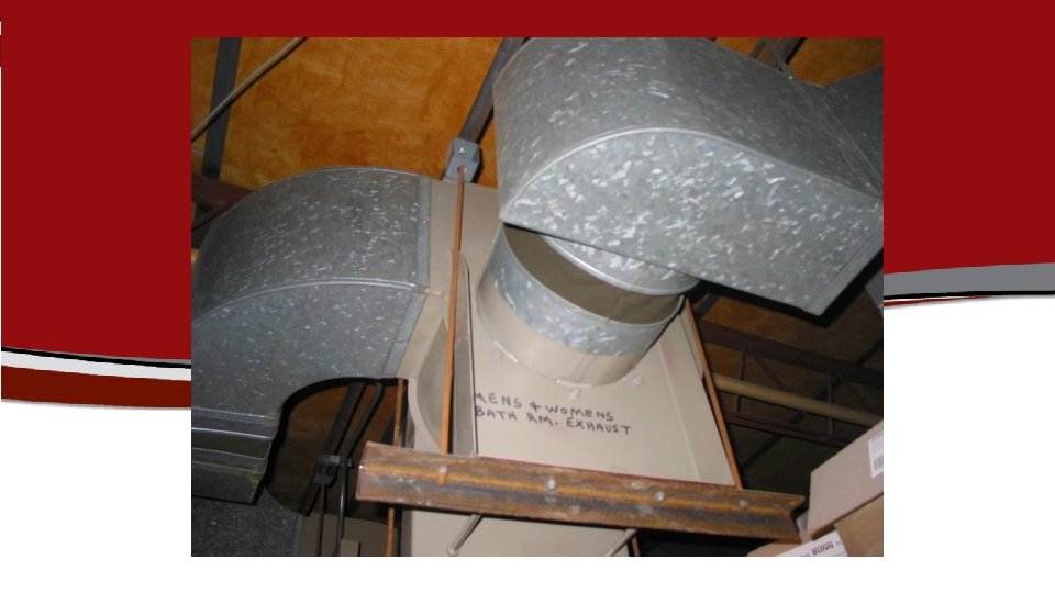
System Effect 1 ST Definition • Installed duct configuration does not match tested duct configuration 15
Installation Type D —Ducted Inlet / Ducted Outlet Piezometer Ring Fan Static Pressure Test Fan Nozzles Fan Airflow Auxiliary Fan Plenum Installed Fan 16
AMCA Catalog Ratings • “Performance certified is for installation type: • • A: Free inlet, Free outlet” B: Free inlet, Ducted outlet” C: Ducted inlet, Free outlet” D: Ducted inlet, Ducted outlet” 17
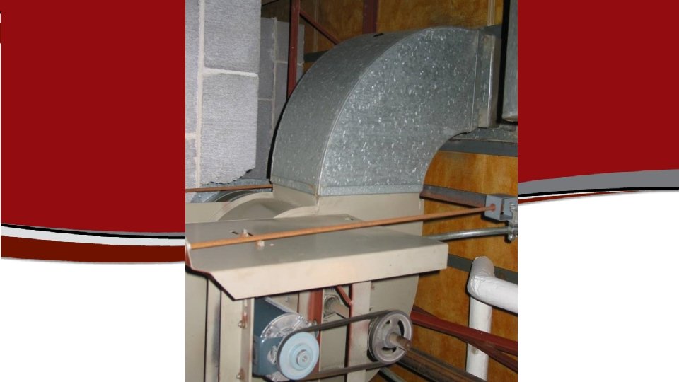
System Effect 2 nd Definition • Even when the tested duct configuration matches the installed duct configuration, improper duct design can introduce adverse flow conditions 18
Elbow Example 19
33
34
AMCA Publication 201—Plenum Example Plenum 34
Plenum Example E-F duct friction at 5000 CMH (Q) 747 Pa (duct design) E contraction loss-plenum to duct 50 Pa (part of duct system) E PS energy required to create velocity at E D PV loss (also PT loss) at D as result of air velocity decrease 125 Pa (part of duct system) 0 Pa PS does not change from duct to plenum at D C-D outlet duct on fan as tested 0 Pa ---------- REQUIRED Fan PS 922 Pa 35
Plenum Example Plenum 36
Plenum Example D-E duct friction at 5000 CMH (Q) 747 Pa (duct design) D contraction loss-plenum to duct 50 Pa (part of duct system) D PS energy required to create velocity at D B-C SEF B-C PV loss (also PT loss) at C as result of air velocity decrease 125 Pa (part of duct system) 149 Pa 0 Pa PS does not change from duct to plenum at C --------- REQUIRED Fan PS 1071 Pa 37
Plenum Example from AMCA 201 • Assuming: • Use of the same fan for both systems • Can attain both operating points with a change in speed ( ) 2 PC = NC N P ( ) 1/2 PC P • Speed change ratio; (1071/922)0. 5 = 1. 08 38
Plenum Example from AMCA 201 3 HC = ( ) NC N H H, Fan Power • 1. 083 = 1. 25 (Fan Law for Power) • The increased in power consumption to overcome System Effect is about 25% 42
8% Speed Change 800 2. 5 700 2 25% More H 500 1. 5 400 1 300 Power, H Pressure, P 600 200 0. 5 8% More Q 100 0 2 4 6 8 10 12 14 Air Flow, Q 40
Inlet System Effect SYSTEM EFFECT DESIGN RESISTANCE ACTUAL FAN CURVE WITH SYSTEM EFFECT CATALOG PERFORMANCE CURVE AIRFLOW DEFICIENCY DESIGN AIRFLOW 41
Outlet System Effect ACTUAL SYSTEM WITH SYSTEM EFFECT CALCULATED SYSTEM WITH NO ALLOWANCE FOR SYSTEM EFFECT LOSS AT DESIGN AIRFLOW DESIGN RESISTANCE CATALOG PERFORMANCE CURVE AIRFLOW DEFICIENCY DESIGN AIRFLOW 42
Speed Changes • Before Increasing Speed • Check with the manufacturer for max safe operating speed • Determine expected power increase • Motor size • Electric Service • Expect more noise 43
Rules of Thumb • Minimum 2. 5 duct diameters on Outlet • Minimum 3 to 5 duct diameters on Inlet • Avoid inlet swirl 49
Recommendations • Allow enough space in the building design to allow for appropriate fan connections to the system 50
Recommendations • Use allowances in the design calculations when space or other factors dictate less than optimum arrangement of the fan outlet and inlet connections 51
Recommendations § Include adequate allowance for the effect of all accessories and appurtenances on the performance of the system and the fan 52
Questions? Mark Stevens Executive Director AMCA International mstevens@amca. org 56