Gauteng Department of Education Further Education and Training


 up from the bottom of each")


")


- Slides: 100
Gauteng Department of Education Further Education and Training Directorate Curriculum Coordination Woodworking Technology CAPS for Technical High Schools Grade 11 Woodworking Term 2 Joining (Specific)
LESSON PLAN 29 TABLE OF CONTENT 1. 1. 1 1. 2 1. 3 1. 4 1. 5 1. 6 1. 7 1. 8 1. 9 2. 2. 1 2. 2 2. 3 Methods of joining the following items: Skirting to a wall Architrave to a door frame Door frame to a wall Cornice to a ceiling Cupboard to a wall Shelf to a wall Mirror to wall and frame Window pane to a casement stile Handles to doors Application, uses and drawings of the following woodworking joints: (exploded and assembled views) Mortice and tenon joint Double mortice and tenon joint Bare face tenon
1. Methods of joining the following items: 1. 1 Skirting to a wall: A baseboard (also called skirting board, skirting, mopboard, floor moulding, as well as base moulding) is a (generally wooden) board covering the lowest part of an interior wall. Its purpose is to cover the joint between the wall surface and the floor. It covers the uneven edge of flooring next to the wall; protects the wall from kicks, abrasion, and furniture; and can serve as a decorative moulding. At its simplest, baseboard consists of a simple plank nailed, screwed or glued to the wall; however, particularly in older houses, it can be made up of a number of mouldings for decoration.
Plastic baseboard comes in various plastic compounds, the most common of which is UPVC. It is usually available in white or a flexible version in several colours and is usually glued to the wall. Vinyl baseboard is glued with adhesive and can be difficult to remove or to replace. It has a long lifespan, which can mean lower maintenance. Wooden baseboard can be available in untreated, lacquered or prepainted versions. Prepainted baseboards can be made from a single piece or finger jointed wood, often softwoods, while hardwoods are either lacquered, or raw for staining and made from a single piece of wood.
DIFFERENT PATTERNS:
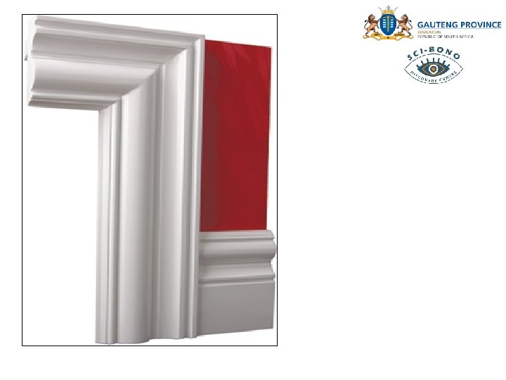
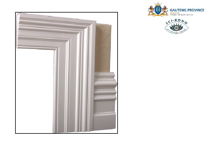
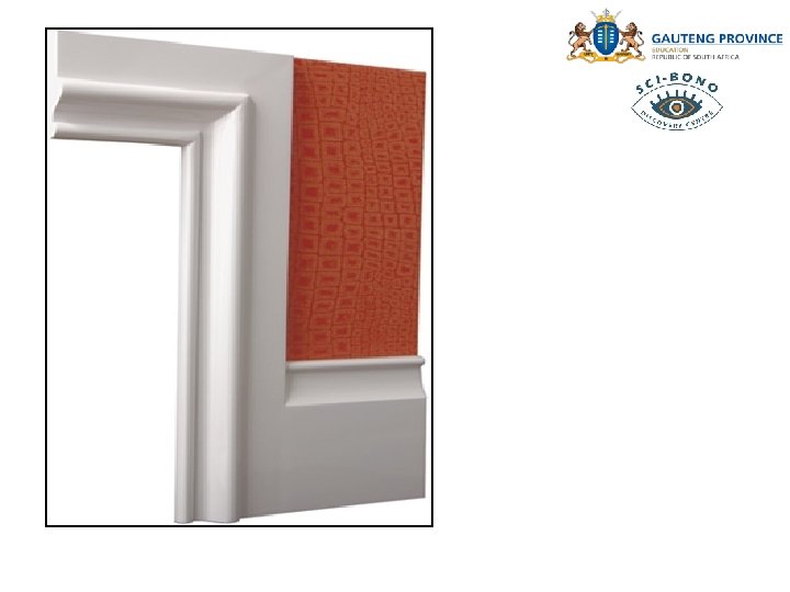
1. 2 Architrave to a door frame: 1. Architraves are also known as Facings, the standard sets are normally supplied as 5 lengths which gives enough for two sides of a door frame/surround. 2. Take the architrave and place against the door frame/surround, use a sharp pencil to mark the architrave at a height just above the top corner of the door frame where it meets the lintel just above the door. 3. Using a mitre square and sharp pencil, mark the mitre, the 45* angle upwards from the original 1 st pencil mark.
4. Use a small tenon saw to cut the mitre, sometimes it's better to angle the cut slightly back at an angle while continuing to follow the pencil mark, don't remove the pencil mark with the cut, repeat this process for the other architrave legs. 5. There are two basic ways of cutting the lintel sections of architrave, type one is to go through the process of lining up the lintel architrave with the architrave legs and transposing a pencil line from each edge of the leg width, type two is simpler, having loosely pinned the architrave legs to the frame, ease them off or away slightly from the frame and drop the architrave lintel behind the legs until the lintel us at the correct position, use a sharp pencil to mark the leg mitre shape to the lintel architrave and cut the mitres as described previously
6. Pin/nail each architrave piece to the frame, pins are normally spaced 50 mm or so apart over the width of the architrave at slightly different heights to each other and tapped in at a slight angle to the centre of the width of the architrave, this grips the architrave better and prevents the pins splitting through the frame rebate. 7. Tap the pins with a nail punch below the surface of the architrave, fill with matching wood colour and lightly sand immediately rather than waiting for the filler to go hard, It's easier and tidier.
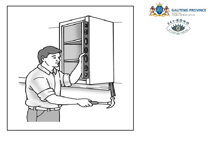
1. 3 Door frame to a wall: Assembling the lining The door lining head is housed out either side for the legs to slot into. Sometimes the housing is the same thickness as the leg, other times only half the thickness is removed and the top of the lining leg has a half tenon that slots into the head. In this case, make sure you put the legs in the correct way around to allow for your doors width.
Personally if given a choice i'd always choose the lining where the housing is the same thickness as the leg (above left) because if the leg happens to get damaged or there's a nasty knot/shake in one side you can just spin it around and use the good side not possible if it will only work one way around. The head of a door lining set is also often housed out on both sides to accomodate two different sizes of door. If you are making a door lining up yourself from stock timber add around 5 mm (1/4") to the width of the door to ensure a gap either side of the door when it's hung.
Determine and drill through the housed section you want. I put 3 clearance holes in each slot. Then using plenty of PVA wood glue assemble the lining and screw the legs in with 80 mm screws. Finally, cut the excess timber off the head (you can leave a bit of this on if the opening is much wider as it may help keep the frame in place while you work). Squaring the door lining It`s easier to install if you've already braced it in a perfectly square position. If the frame you are installing is a hatch like a loft trap you can check it is square by measuring from corner to corner (measurements should be identical).
If fitting a normal door frame, it's far easier to install if you first brace the legs at the bottom so they are held the correct distance apart and also brace the top corner of the frame diagonally. This will keep it held square while you're working on it in the opening. It also makes it easier to move into position as it's not trying to pull apart etc. To brace the bottom at the same width as the top, grab a piece of batten and cut it to the same overall width as the head (outside to outside measurement of the legs).
Mark with a tape measure 150 mm (6") up from the bottom of each leg and nail the batten to that line, flush with the outside. This will keep the bottom of the legs the same distance apart as the top is. Some carpenters repeat this on both sides to keep the legs really straight.
Next, grab another batten and fix it diagonally from the head of the door lining to a leg like in the pic above, to hold the top at a perfect 90° angle. To do this either use the 3 4 5 method or a large framing square to hold it at 90° (more accurate/quicker) while you brace it. (Nail toward the outer edge without splitting so the architrave will cover the nail holes up later). When the frame is braced up it should look like:
Installing the lining: Step 1: - Level the head: Place the door lining in the opening and check that the head is level. Always mark the hinge side straight away so if you remove the frame to work on it, you’ll know which way to put it back in. If the head isn't perfectly level put a wedge under the side that needs to go up until it is perfect. Measure the gap under the wedged side, and cut that much off the bottom of the other leg. This should make the lining sit level when you put it back into the opening.
Step 2: - Fixing the door lining - hinge side first: The hinge side is the most important one to get straight, solid and level at this point. When fitting to studwork, I drill and countersink 8 -10 holes in each leg, in pairs 100 mm down from the top, the same up from the bottom and then equally spaced in between. By screwing the frame in place you can adjust it by winding the screws in/out later and wedging behind it.
If the wall you are fitting to is masonry you'll want to space the screws so they fall in the middle of the brick or block instead because too close to the edge of a brick and it'll just split or shatter. It's not always easy to get a decent fixing in the cement joint either. If you won't be able to see the bricks when the lining is in because the wall is a previously plastered one mark the center of the bricks on the face of the wall or lining before sliding the frame in. Use 80 -100 mm long screws and red/brown rawl plugs. Next, fit the lining in position and screw the hinge side up first, making sure it is perfectly level and equally overhangs the wall behind. Put a 1800 mm spirit level on the face to check it is straight, and use either timber packers (I rip a load of different size packers down) or folding wedges like in the picture on the right to wedge out any hollow areas.
Step 3: - Fix the opposite side: Using a spirit level held across the face of the lining like in the drawing below (it's a birds eye view), make sure the frame is parallel with the wall, and there is an equal overhang before screwing the top of the other side. This is important because the plasterer will want to use a straight edge exactly how you are using a spirit level now to make sure the wall is perfectly flat. If it's a studwork wall it's still important because the door lining needs to maintain the flatness of the wall when the plasterboard is screwed on.
Then, sight the frame through to make sure it is 'in wind'. This is done by sighting one edge of the door frame through to the opposite edge like below. As you look through, let your eye wander from top to bottom and check the legs are parallel.
The picture below shows a good and bad lining that doesn't sight through/is out of wind. Again, this is important because if you get it wrong the wall won't be flat and when the door is hung it won't close properly. The top will either close before the bottom, or vice versa.
Installing several door linings in a corridor: Occasionally you'll come up against a situation where several door linings need to be installed in a hallway or corridor and they'll all need to be the same height and perfectly in line. It's more common in commercial projects, and buildings like schools/hospitals etc.
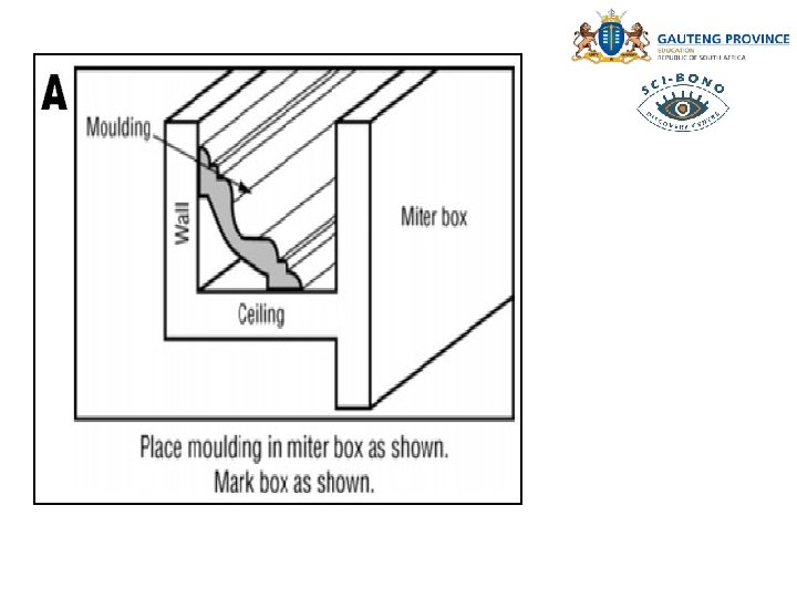
To do this I fit one door frame correctly at each end, and then pull string lines tight from one to the other. This makes installing the frames in between a lot quicker and easier as you simply put them up to the lines and screw in place, before packing out to make sure the sides are straight. 1. 4 Cornice to a ceiling: Before Starting: v v Start by measuring your room to determine linear meters of moulding needed. Add 10% to 15% of total length for cutting waste.
v v Clean all surfaces free of dirt and loose particles with a clean cloth or sponge. Make sure area is completely dry before installing product. To Mitre Corners: v v v The key to successful mitred corners is placing the moulding correctly in the mitre box. The moulding should be placed in the box so that the ceiling bedding edge of the moulding lies against the bottom of the box or saw and the wall bedding edge of moulding lies against the side of the mitre box opposite you. TIP: Before cutting, label the mitre box bottom "CEILING" and the side with "WALL" [A].
v Cut all mitres and butt joints before you install moulding. Cutting of Inside Corners: v v v Take two pieces of moulding that will be used for your first inside corner. Place the LEFT length of moulding in the box as described above and cut at 45 degrees. Your saw should point left [B].
v v Next place the RIGHT length of moulding in the mitre box. Cut the right mitre with your saw pointing right [C].
v Check your cuts by placing the two mitred ends together, to insure a good fit.
Mitreing Outside Corners: v v Take two pieces of moulding that will be used for your first outside corner. Place the LEFT length of moulding in box as described above and cut at 45 degree – your saw should point right [D].
v Next place the RIGHT length of moulding in the mitre box and cut the right mitre with your saw pointing left [E]. v Check your cuts by placing the two mitred ends together, to insure a good fit
Mitreing Outside Corners: v v When moulding lengths do not span the entire length of a room, you will need to “butt” two moulding lengths together. Lay the moulding in the mitre box the same as described above and cut a straight edge [F].
General Installation: First mark the entire length of wall around the room with your chalk line box and pencil. You will mark the bottom edge of the moulding. v Apply a continuous bead of acrylic cornice adhesive along the backside top and bottom edges of moulding [G]and at butt joint ends. v
v v v Use adhesive to fill any gaps. Gently press the moulding into place. Apply cornice glue to moulding edge and smooth excess with your finger or putty knife, giving the appearance of the moulding being part of the wall [H]. v Wipe any excess adhesive from edges and clean a damp cloth.
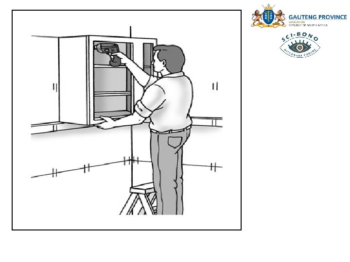
1. 5 Cupboard to a wall: Install wall cabinets before you install base cabinets so you don't have to work above the base cabinets. The open area of the floor allows you, your helper, and your step ladder clear access. These steps describe installing framed cabinets. Frameless cabinets are installed in much the same manner except when connecting adjoining cabinets. To join frameless cabinets, use wood screws that are just shorter than the thickness of the two cabinet sides.
It's time to install the first wall cabinet: 1. Transfer stud locations from the wall to the inside of each cabinet before you lift it into place; and drill clearance holes for the mounting screws. Clearance holes, which are the same diameter as the screw, ensure that the cabinet will be drawn tight to the wall by the head of the screw. Measure carefully and measure twice. Drill the holes in the upper and lower hanging rails of the cabinets (the two horizontal pieces of lumber along the top and bottom of the back of the cabinet). 2. Set the first wall cabinet on the ledger strip and 1/4 -inch away from its reference line on the wall; secure the top and bottom of the cabinet to the wall with 3 -inch-long #10 cabinet screws.
Snug up the screws as you go, but don't tighten them completely. You'll go back later for a final tightening of all the screws after cabinets are aligned with each other, joined together with screws and plumbed. If you have a helper, have her hold the unit in place while you secure it with screws. If you're working alone, cut some lengths of lumber and make a V-shaped notch in one end. Use these pieces as braces by placing the notch against the bottom of the cabinet and wedging the lumber up to hold the cabinet in place. Put a rag or piece of cardboard over the cabinet where the notched lumber will go to protect the cabinet's finish.
3. Position the second cabinet on the ledger and next to the installed cabinet. Attach it with screws as you did the first one. 4. Join the two cabinets with two clamps, located about 1/4 of the distance from the top and bottom. Use wooden screw or short bar clamps with padded jaws that won't mar the cabinets. As you tighten the clamp, ensure that the face, top, and bottom of the two frames are all perfectly flush. 5. Drill clearance holes through the face frame, countersinks so that the screw heads will be flush with or below the surface, and pilot holes in the adjoining cabinet. Locate the holes at the hinge positions so when the hinges are installed, the screw heads will be concealed. The easiest way to drill these holes is all at once, using an adjustable combination bit.
6. Drive 2 1/4 -inch drywall screws into each hole and remove the clamps. If the holes are not properly sized or if you overdrive the screws, they can easily snap off. Use the proper bits and adjust the clutch on your drill/driver to limit the torque. 7. Install the remaining wall cabinets along this wall in the same manner and then remove the ledger. 8. If the plan calls for a filler strip at a particular location, clamp it to the face frame and attach it as you would attach two cabinets together.
9. Starting at the corner, plumb the cabinets using the reference line on the adjacent wall and a 2 -foot level, and insert shims as required. Install shims behind the cabinet at the bottom or top as indicated until the cabinet is plumb and the proper distance from the reference line. Back out an installation screw, insert the shim until the cabinet is plumb and drive in the screw. When all cabinets are plumb, trim off the shims. 10. Similarly complete the installation of cabinets first on adjoining walls and then other walls. Clamp the filler strip in place and drill 3/16 -inch pilot holes through the cabinet face frame and filler strip, using a countersink bit to recess the screw head into the face frame. Secure the strip with 3 -inch drywall screws.
11. Reinstall the doors and check each one for smooth operation. Be careful when redriving the screws for the hinges. The screws are generally made from a fairly soft metal, which makes the heads easy to strip and the shafts easy to snap off. 1. 6 Shelf to a wall: 1. Read the installation instructions for the shelving unit to verify that all installation hardware is included. The equipment may consist of simple wooden brackets or more complex vertical standards on which hang metal supports. All will generally require screwing hardware into the concrete wall.
2 Bring the instructions and some example screws to your local home center. Ask the clerks for concrete or masonry wall anchors that the installation hardware can fit. They may recommend that you use screws appropriate to the wall anchors rather than the ones that came with the shelf supports. 3 Position the supports against the wall at the distances recommended by the installation instructions. For example, a 36 -inch long shelf that is 10 inches deep may need only two brackets positioned 32 inches apart. Use a bubble level or laser level to ensure that the supports are level with each other. Using your pencil, mark the center of each support hole on the wall. Set the supports aside.
4 Insert your masonry drill bit into the drill. The installation instructions will define the size of the bit and the depth of the hole. If you do not have an appropriate bit, consider renting a hammer drill from your local hardware store. Bring an example of the wall anchor you previously bought, so the clerk can give you the correct bit for your rental. 5 Wear your safety goggles and mask. Then drill a hole into each of the marks you previously made. 6 Insert the wall anchors into the holes. Position the shelf supports so their holes line up with the wall anchors.
Insert the screws into the holes of the support and then into the anchors. Turn the screws clockwise until they securely fasten the supports to the shelf. Then hang the shelves from the supports. 1. 7 Mirror to wall and frame: Plan where the mirror is to be installed. Use a stud finder to locate the studs in the wall. Make sure there are no pipes in the vicinity that could be damaged (particularly in a bathroom). Most products are supplied with wall mounting screws and raw plugs to fit the mirror. If, for whatever reason, the walls where the mirror is to be placed do not suit the supplied screws and inserts, find more suitable ones to use.
Hold the mirror against the wall where it is to be hung. Use a pencil to mark the corners on the wall (ideally get someone else to hold the mirror or do the marking). Do not make too heavy a mark so the pencil can be easily removed afterward. Measure from all the edges of the pencil marks on the wall. Then measure where the fixing brackets sit on the mirror and transfer those measurements to the wall. This will indicate where the drill holes need to be made. Drill the holes required using a suitably sized drill bit for the material being drilled into. It is always best to start with a small piece and make the hole larger if needed. Once the holes are made, push the raw plugs into them. Then screw in the mounting screws.
Once the screws are inserted and are secure, carefully mount the mirror by fitting the screws into the mounting holes on the back of the mirror. Make sure the mirror is straight, level, and secure against the wall. ALTERNATIVE WAYS TO HANG MIRRORS: If a simpler or more temporary method would be more fitting, there are numerous other possibilities for mounting mirrors. Small Clips There are usually 2 types of clips used for wall hanging. One has a sticky adhesive backing which can be fixed onto the wall.
These are useful, but ensure that they are stuck in the correct place as they can be difficult to remove once fixed. The second type needs to be screwed into the wall. Clips are useful as they are usually hidden behind the mirror itself so are not very intrusive. There are usually 4 of them per mirror, one for the top, one for the bottom, and one per side. Rods or Frames These can come in many different styles to suit the modern home. They are more visible than clips, but are appropriate for larger mirrors. Some can be fixed to the ceiling, others to a dado rail. Some fix solely to the top of the mirror (for lighter ones), others to all four edges. Rods and frames can also come in a variety of styles to suit any home, from plastic to aluminium or other coloured metal. Special Tips for Hanging Heavy Wall Mounted Mirrors Hanging heavy mirrors can be one of the more difficult jobs in the home. There are some fixtures that can be used specifically for mounting heavier items.
D-Rings These are fixtures that wire is threaded through and attached to the mirror. They are strong and not very intrusive, and can usually be bought from hardware suppliers. Anchors This type of fixture is a horizontal design that fits into the wall in the form of a wing, thread, or sleeve anchor that easily works with the existing wall and secures into and against the wall. Heavy Wire Using a thicker and stronger grade of wire gives a heavy hanging item an extra piece of strength should the installation fail.
Mating Wood Strips For the DIY-expert, a suitable solution is to create interlocking pieces of wood that dovetail into each other. One is installed level with the floor on the wall, and the other is secured against the back of the mirror. Mirror Mount If possible, one way of giving a heavy mirror some extra support is by stabilising it using a dresser or another piece of furniture. It is even seen with smaller mirrors such as dressing table mirrors. Even if the mirror and piece of furniture are not part of the same set, they can still be fixed together by using wooden runners to screw the two pieces together. The mirror can also still be fixed to the wall at the same time.
Frames: For mirrors that do not come with a frame, it is possible to make one to fit around it. Wooden pieces can be fixed around or behind the mirror to act as support on all edges. 1. 8 Window pane to a casement stile: Installing a new pane of glass is called glazing, and it is simpler than you may think. Window sashes are made with a lipped channel, called a rabbet, that holds the glass. A window’s rabbet is similar to the groove or notched edge around the back side of a picture frame where the glass rests. Glazing putty and small, pointed metal tabs called glazing points hold the glass securely. Most glass is installed on the outside of the window. If you can’t reach yours safely, remove the sash from the inside and install the new pane on a work table.
1 Scrape off old putty around the rabbet or notch where the glass fits with a putty knife or a 5 -in-1 painter’s scraping tool, then sand the rabbet lightly with fine-grit sandpaper. 2 Brush a thin coat of linseed oil on the sanded wood with a small paintbrush. 3 Scoop out glazing putty from the container and work it around in your hands until it is soft and pliable. Putty is usually stiff straight from the can. 4 Press the kneaded putty into the rabbet. Use more putty than you need, to the point of overfilling, to ensure even coverage all the way around.
5 Put on heavy work gloves and set the glass pane on the putty. Push the edges of the glass into putty in the rabbet with even pressure. Don’t push at the center of the pane, which can break the glass. 6 Place a glazing point flat against the glass near a rabbet edge with the tip of the point against the rabbet. The lip of the point should face out. 7 Push the lip of the glazing point with the end of a putty knife, forcing the sharp tip of the point into the rabbet. The glazing point should remain flat against the glass. Stop pushing when the tip of the glazing point is fully seated into the wood and the lipped edge butts against the rabbet. Add more glazing points every 4 inches around the pane.
8 Scoop out more glazing putty and knead it until it is soft and pliable. Roll the putty between your hands into a long, thick rope. 9 Press the rope of putty against the glass and the edge of the rabbet around the perimeter of the pane, using more putty than you need. 10 Place the end of the putty knife blade on the edge of the rabbet with the corner of the blade just touching the glass. Hold the putty knife as close to a 45 -degree angle between the rabbet and the glass as possible. Pull the knife along the rabbet, trimming away the excess putty from the rabbet and the glass as you pull. Repeat on all four sides of the pane.
11 Pull up the excess putty that you trimmed off the glass and rabbet. 12 Trim off excess putty on the opposite side of the glass with the putty knife. 1. 9 Handles to doors: Most ready-to-use doors from the DIY stores have a recess for a lock in the edge. There are usually no holes on the front and rear sides of the door (for the door handle and if required the key). You can fit a standard mortise lock with a sprung latch operated by the door handle and a key‑operated locking bolt, or a security lock. Some new doors do not have a recess for the lock, which means you will have to cut this out yourself.
1. Locks in interior doors Interior doors are usually fitted with a mortise lock with a latch operated by the door handle or knob. Where the door is selfclosing, the latch has an angled or rounded edge and is sprung so that it automatically locks when the door is closed. The same lock can be used in doors that open both to the left and the right. Lockable rooms in many cases also have a locking bolt operated by a key. In contrast to the latch, the locking bolt does not have an angled or rounded edge and is not sprung.
2. Locks in exterior doors Cylinder locks are the most suitable type for exterior doors. Simple mortise locks are not secure enough for exterior doors. Cylinder locks are fitted into the lock body, and can easily be replaced without having to change the whole lock mechanism.
3. Rim lock If it is not possible to use a mortise lock, you can fit a rim lock which is mounted on the surface of the door. This may be the case for example with a door that is less than 40 mm thick. With a thin door like this, the recess for a mortise lock would weaken the door structure too much. Rim locks are available with a sprung latch and/or a locking bolt. They are normally only used on exterior doors.
4. Selecting the direction of opening First, check in which direction the door opens. It doesn’t matter whether the door opens to the inside or outside. According to the European standard, examples A and C in the illustration below open to the left, and B and D open to the right.
5. Adjusting the lock If the latch of the lock faces the wrong way for the opening direction of the door, you will need to turn it round. At the side of the lock body is a small pin which you can push upwards with a narrow screwdriver (1). The latch will then fall forwards out of the lock body (2). You can then turn it round to face the other direction (3) and push it back into place (4).
6. Mark out the position of the lock Find the right height for the lock – normally the door handle is at a height of 105 cm. Mark out the positions of the top and bottom of the lock with a pencil on the left or right side of the door. Extend the lines you have marked to the narrow edge of the door using a try square. Once you’ve marked out the top and bottom of the lock on the door edge, draw the vertical center line between them. Place the back of the lock body on the center line and mark out the shape of the lock body with a pencil. This outline now shows where the recess has to be cut in the door edge.
7. Drill out the recess in the door Now mark out the depth of the recess in the door edge. Measure the total depth of the lock body including the retaining plate, which is recessed into the door edge. Set the depth stop of your drill to the right depth, allowing an extra 5 mm. If your drill doesn’t have a depth stop, you can stick a piece of tape to the drill bit to indicate the right depth. Stay within the marked outline – the lock has to fit exactly, but without being forced into place.
8. Finishing with a chisel Once you’ve cut out the recess roughly with the drill, you can finish the edges in a straight line with a chisel. Finish the recess neatly until it’s exactly the right shape for the lock body. Keep checking the fit while you’re working, so you don’t make the recess too large.
9. Mark out the retaining plate Once you’ve fitted the lock body in the recess, mark out the edge of the retaining plate with a pencil. Remove the lock from the recess.
10. Make a cut-out for the retaining plate Now you can use the chisel to make a cut-out for the retaining plate. This should have a depth of about 3 mm, just enough for the retaining plate to fit into neatly. The outer face of the retaining plate should be flush with the door edge.
11. Mark out the hole for the door handle Now you can mark out the holes for the door handle and if applicable the key. Hold the lock body against the front side of the door, with the retaining plate exactly over the recessed part. Mark out the place where the hole needs to be made with a pencil, and then use an awl to make a starting hole for drilling.
12. Drill the hole for the door handle Use a drill bit with a diameter that allows the spindle of the door handle to turn freely. Drill the hole exactly horizontally through to the other side of the door. If necessary, do the same again for the key or cylinder holes. Remove any irregularities in the holes with a wood file. TIP! Fix a spirit level to your drill, then it’s easy to drill horizontally.
13. Fix the retaining plate Place the lock back into the recess in the door and secure it with long woodscrews. Fit the door handle and any other fittings. Tighten the handle securely, because it is used often and with a lot of force. If there is any play in the door handle it can cause unsightly damages.
14. Mark out the strike plate on the door frame After you’ve fitted the lock in the door, you need to fit the strike plate to the door frame. First mark out the place where the strike plate has to be fitted. Turn the key so the locking bolt protrudes from the lock, and hold the door against the door frame. Use a sharp pencil to mark lines on the door frame at the top and bottom of the locking bolt and the latch. Then with the door open you can extend those lines across the inside of the door frame. With these lines as a guide, you can use the strike plate as a template. Then you can easily mark out the overall outline of the strike plate and the recesses for the latch and locking bolt.
15. Make a cut-out for the strike plate Make a cut-out of about 3 mm deep into which the strike plate fits neatly. The outer face of the strike plate should be flush with the edge of the door frame. The depths of the recesses in the door frame must be equal to the lengths of the latch and locking bolt. Cut out these recesses deeply enough so the latch and locking bolt can fall into them fully. Fix the strike plate to the door frame with long wood screws, and check once again that the latch and locking bolt fall easily into place. If they touch the strike plate you can enlarge the opening slightly with a file, but do this very carefully. If the fit is too loose, the door may rattle when there’s a draft.
16. Bend over the lip of the strike plate You can carefully bend over the lip of the strike plate with a small plastic hammer, so that it neatly follows the contour of the door frame. The lip is meant to protect the door frame from the impact of the latch, each time the door closes.
2. Application, uses and drawings of the following woodworking joints: (exploded and assembled views) 2. 1 Mortice and tenon joint: A mortise and tenon joint is one in which the rectangular end (the tenon) of one piece fits into a rectangular hole (the mortise) of the same size, in the other piece. Mortise and tenon joints are made in a number of different types. The blind mortise and tenon is the most common. It is used extensively in cabinetmaking for joining rails to legs or stiles, and in many other constructions well. When properly designed, proportioned, and well made, mortise and tenon joints are strong and neat in appearance.
TENON AND MORTISE TERMINOLOGY Tenon terminology
Mortise terminology
Through mortise and tenon joint
Corner through mortise and tenon joint
Blind mortise and tenon joint
Corner blind mortise and tenon joint
Angled haunched mortise and tenon joint
Angled haunched barefaced mortise and tenon joint
Application of haunched tenon joint to door frame
End wedged through tenon and mortise joint
Wedged through tenon and mortise joint
Haunched tenon and mortise joint
Interlocking tenon and mortise joint for seat rails of chair to leg
Long and short shouldered tenon and mortise joint
Loose tenon and mortise joint
Open through tenon and mortise joint Bridle joint
Round tenon and mortise joint
Tenon and mortise joint with mitered face
Tusk tenon and mortise joint
Tenon and mortise joint reinforced with dowel
Tenon and mortise joint for fencing
Skewed tenon and mortise joint
Self wedging tenon and mortise joint
2. 2 Double mortice and tenon joint: Twin tenon and mortise joint
Twin tenon and mortise joint for thick timber
2. 3 Bare face tenon: Barefaced blind tenon and mortise joint