From Simulink to Lustre to TTA a layered


- Slides: 59
From Simulink to Lustre to TTA: a layered approach for distributed embedded applications Stavros Tripakis VERIMAG Joint work with: Paul Caspi, Adrian Curic, Aude Maignan, Christos Sofronis 1
Problem and approach • How to develop embedded software ? – Safely: safety-critical applications – Efficiently: development cost, time-to-market • “Model-based” approach: – High-level design models – Analysis techniques: catch bugs early – Synthesis techniques: correct-by-construction implementations 2
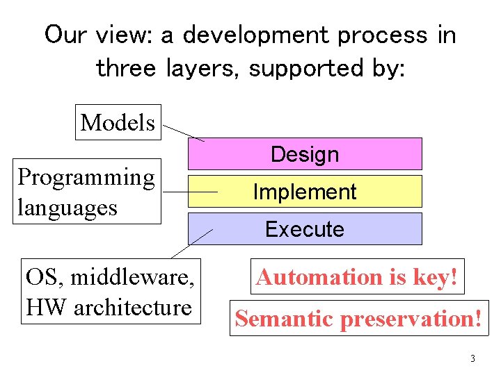
Our view: a development process in three layers, supported by: Models Programming languages OS, middleware, HW architecture Design Implement Execute Automation is key! Semantic preservation! 3
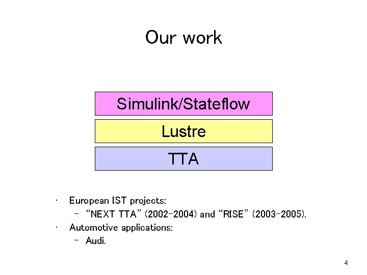
Our work Simulink/Stateflow Lustre TTA • • European IST projects: – “NEXT TTA” (2002 -2004) and “RISE” (2003 -2005). Automotive applications: – Audi. 4
A Simulink model (parts) 5
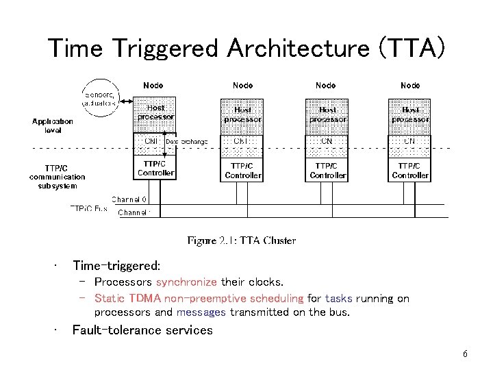
Time Triggered Architecture (TTA) • Picture of TTA • Time-triggered: – Processors synchronize their clocks. – Static TDMA non-preemptive scheduling for tasks running on processors and messages transmitted on the bus. • Fault-tolerance services 6
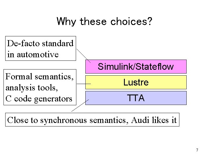
Why these choices? De-facto standard in automotive Formal semantics, analysis tools, C code generators Simulink/Stateflow Lustre TTA Close to synchronous semantics, Audi likes it 7
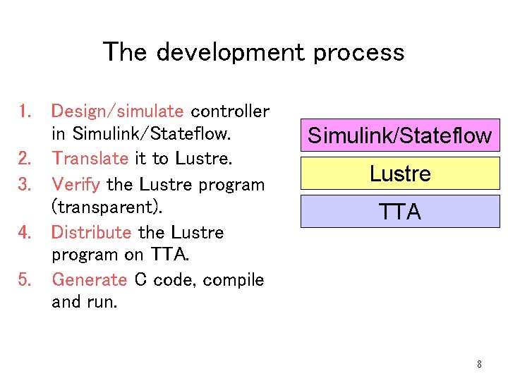
The development process 1. Design/simulate controller in Simulink/Stateflow. 2. Translate it to Lustre. 3. Verify the Lustre program (transparent). 4. Distribute the Lustre program on TTA. 5. Generate C code, compile and run. Simulink/Stateflow Lustre TTA 8
Plan of talk • Translating Simulink to Lustre. • Distributing Lustre on TTA. • Tool-chain and case studies. 9
Plan of talk • Translating Simulink to Lustre. • Distributing Lustre on TTA. • Tool-chain and case studies. 10
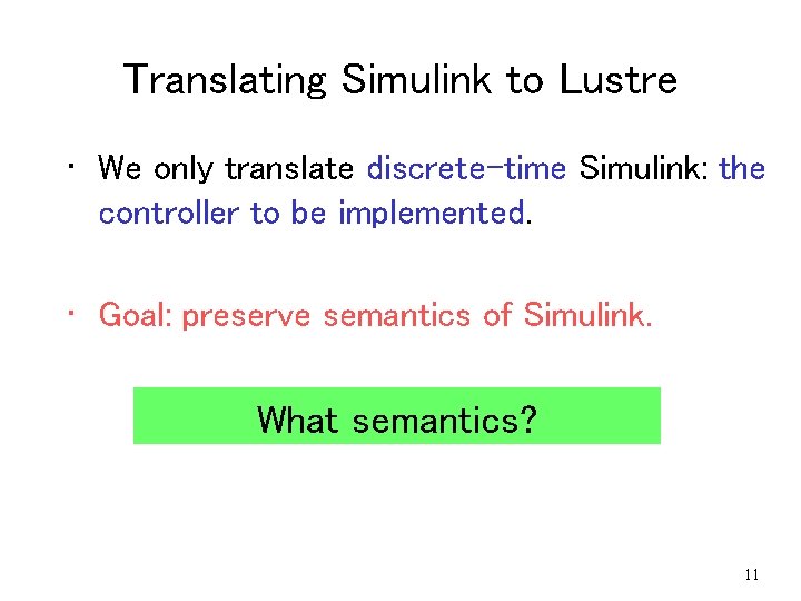
Translating Simulink to Lustre • We only translate discrete-time Simulink: the controller to be implemented. • Goal: preserve semantics of Simulink. What semantics? 11
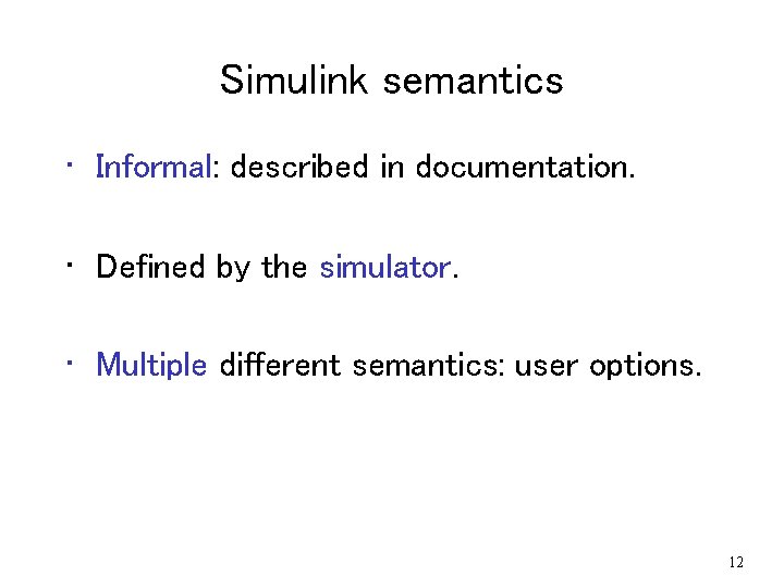
Simulink semantics • Informal: described in documentation. • Defined by the simulator. • Multiple different semantics: user options. 12
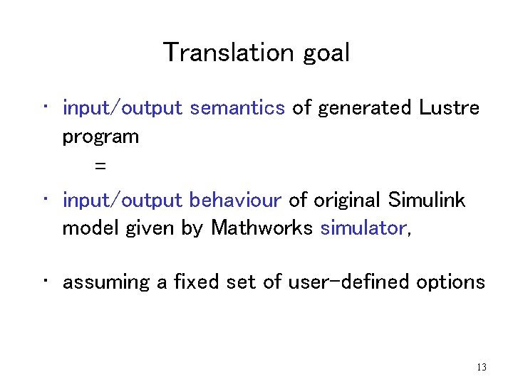
Translation goal • input/output semantics of generated Lustre program = • input/output behaviour of original Simulink model given by Mathworks simulator, • assuming a fixed set of user-defined options 13
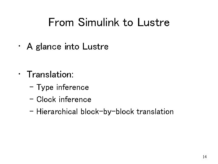
From Simulink to Lustre • A glance into Lustre • Translation: – Type inference – Clock inference – Hierarchical block-by-block translation 14
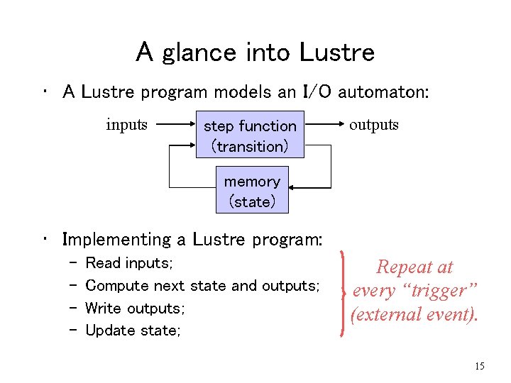
A glance into Lustre • A Lustre program models an I/O automaton: inputs step function (transition) outputs memory (state) • Implementing a Lustre program: – – Read inputs; Compute next state and outputs; Write outputs; Update state; Repeat at every “trigger” (external event). 15
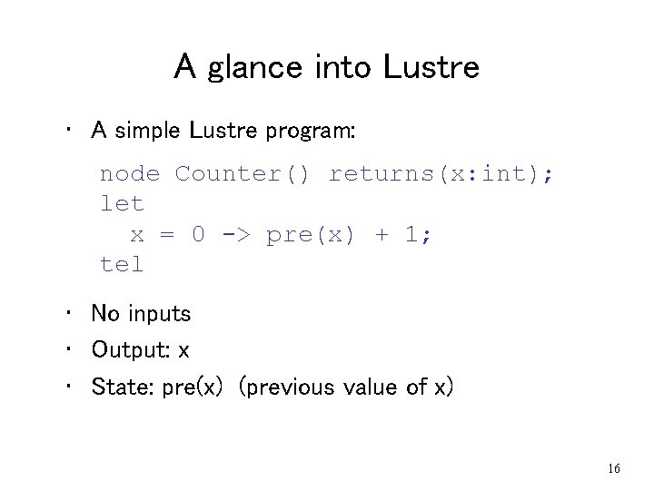
A glance into Lustre • A simple Lustre program: node Counter() returns(x: int); let x = 0 -> pre(x) + 1; tel • No inputs • Output: x • State: pre(x) (previous value of x) 16
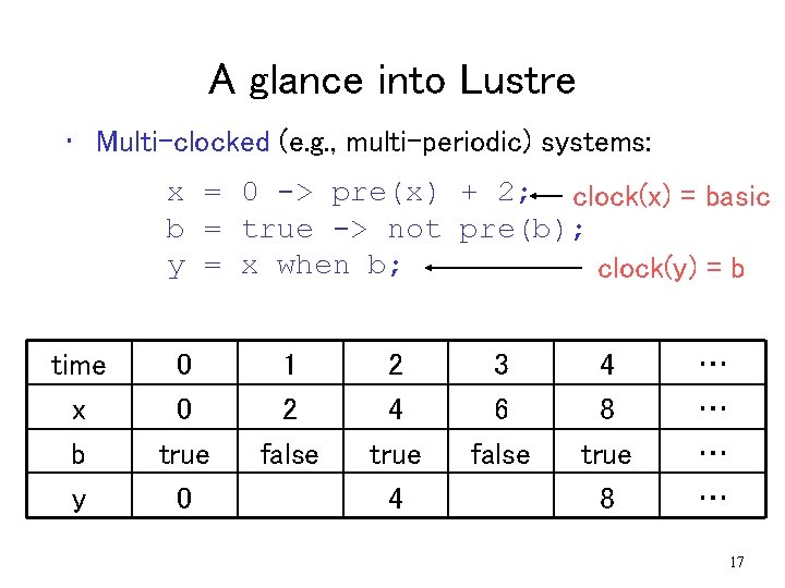
A glance into Lustre • Multi-clocked (e. g. , multi-periodic) systems: x = 0 -> pre(x) + 2; clock(x) = basic b = true -> not pre(b); y = x when b; clock(y) = b time x b y 0 0 true 0 1 2 false 2 4 true 4 3 6 false 4 8 true 8 … … 17
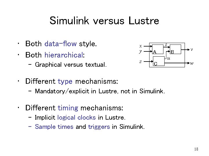
Simulink versus Lustre • Both data-flow style. • Both hierarchical: – Graphical versus textual. x y z s A B u C v w • Different type mechanisms: – Mandatory/explicit in Lustre, not in Simulink. • Different timing mechanisms: – Implicit logical clocks in Lustre. – Sample times and triggers in Simulink. 18
Translation steps 1. Type inference 2. Clock inference 3. Hierarchical block-by-block translation 19
Translation steps 1. Type inference 2. Clock inference 3. Hierarchical block-by-block translation 20
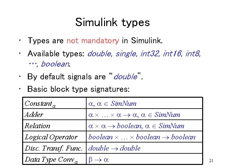
Simulink types • Types are not mandatory in Simulink. • Available types: double, single, int 32, int 16, int 8, …, boolean. • By default signals are “double”. • Basic block type signatures: Constant Adder Relation Logical Operator , Sim. Num … , Sim. Num boolean, Sim. Num boolean … boolean Disc. Transf. Func. double Data Type Conv 21
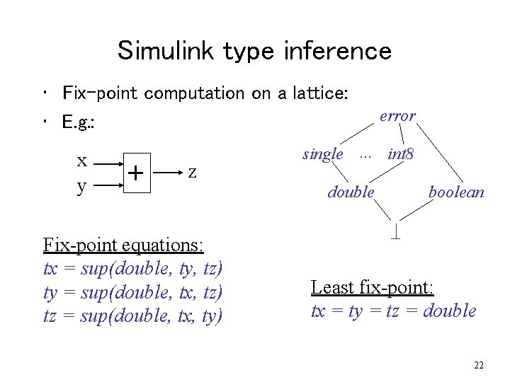
Simulink type inference • Fix-point computation on a lattice: • E. g. : x y + z Fix-point equations: tx = sup(double, ty, tz) ty = sup(double, tx, tz) tz = sup(double, tx, ty) error single … int 8 double boolean _| Least fix-point: tx = ty = tz = double 22
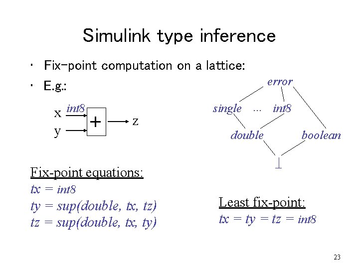
Simulink type inference • Fix-point computation on a lattice: • E. g. : x int 8 y + z Fix-point equations: tx = int 8 ty = sup(double, tx, tz) tz = sup(double, tx, ty) error single … int 8 double boolean _| Least fix-point: tx = ty = tz = int 8 23
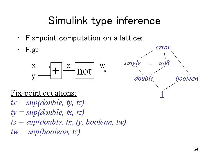
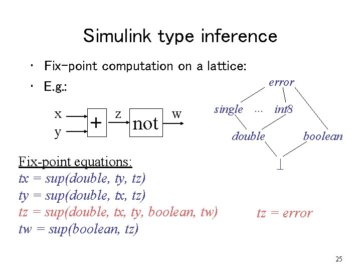
Simulink type inference • Fix-point computation on a lattice: • E. g. : x y + z not w error single … int 8 Fix-point equations: tx = sup(double, ty, tz) ty = sup(double, tx, tz) tz = sup(double, tx, ty, boolean, tw) tw = sup(boolean, tz) double boolean _| 24
Simulink type inference • Fix-point computation on a lattice: • E. g. : x y + z not w error single … int 8 Fix-point equations: tx = sup(double, ty, tz) ty = sup(double, tx, tz) tz = sup(double, tx, ty, boolean, tw) tw = sup(boolean, tz) double boolean _| tz = error 25
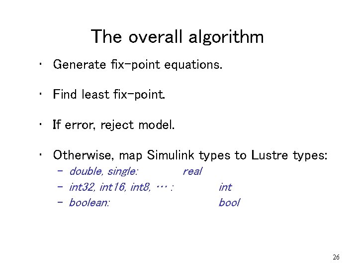
The overall algorithm • Generate fix-point equations. • Find least fix-point. • If error, reject model. • Otherwise, map Simulink types to Lustre types: – double, single: real – int 32, int 16, int 8, … : – boolean: int bool 26
Translation steps 1. Type inference 2. Clock inference 3. Hierarchical block-by-block translation 27
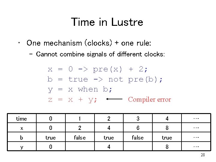
Time in Lustre • One mechanism (clocks) + one rule: – Cannot combine signals of different clocks: x b y z = = 0 -> pre(x) + 2; true -> not pre(b); x when b; Compiler error x + y; time 0 1 2 3 4 … x 0 2 4 6 8 … b true false true … y 0 8 … 4 28
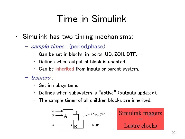
Time in Simulink • Simulink has two timing mechanisms: – sample times : (period, phase) • Can be set in blocks: in-ports, UD, ZOH, DTF, … • Defines when output of block is updated. • Can be inherited from inputs or parent system. – triggers : • Set in subsystems • Defines when subsystem is “active” (outputs updated). • The sample times of all children blocks are inherited. x y z A s B trigger Simulink triggers w Lustre clocks = 29
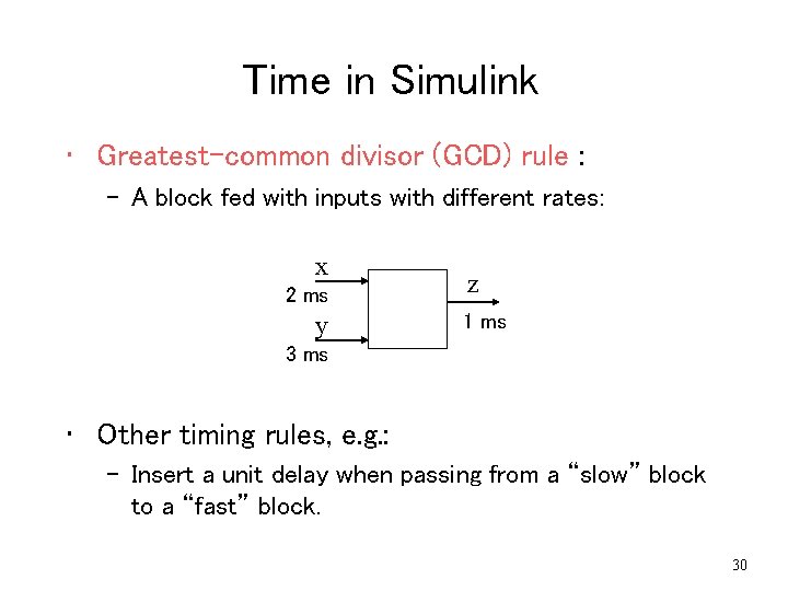
Time in Simulink • Greatest-common divisor (GCD) rule : – A block fed with inputs with different rates: x 2 ms y z 1 ms 3 ms • Other timing rules, e. g. : – Insert a unit delay when passing from a “slow” block to a “fast” block. 30
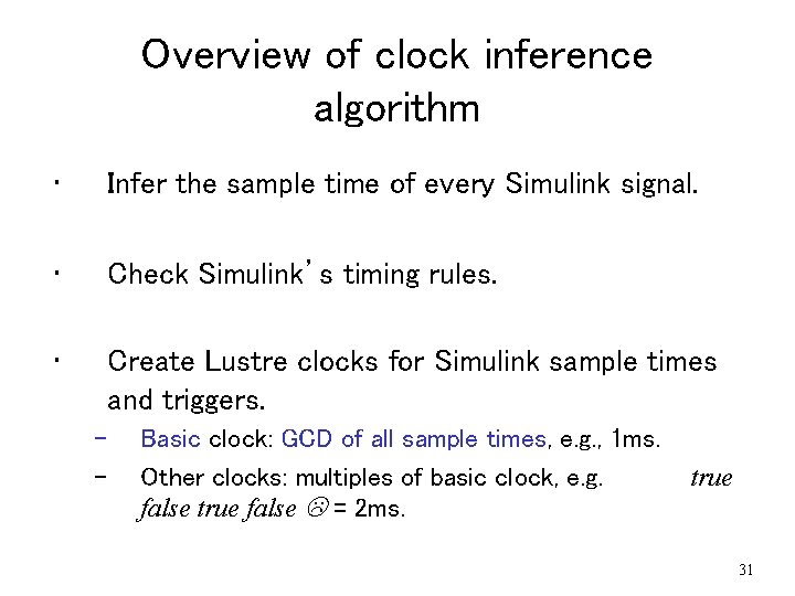
Overview of clock inference algorithm • Infer the sample time of every Simulink signal. • Check Simulink’s timing rules. • Create Lustre clocks for Simulink sample times and triggers. – – Basic clock: GCD of all sample times, e. g. , 1 ms. Other clocks: multiples of basic clock, e. g. false true false L = 2 ms. true 31
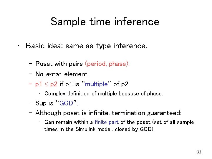
Sample time inference • Basic idea: same as type inference. – Poset with pairs (period, phase). – No error element. – p 1 p 2 if p 1 is “multiple” of p 2 • Complex definition of multiple because of phase. – Sup is “GCD”. – Although poset is infinite, termination guaranteed: • Can remain within a finite part of the poset (set of all sample times in the Simulink model, closed by GCD). 32
Translation steps 1. Type inference 2. Clock inference 3. Hierarchical block-by-block translation 33
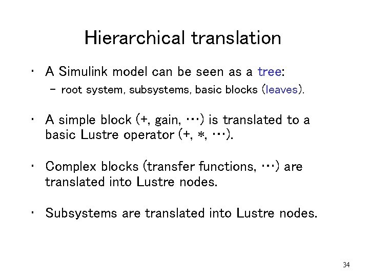
Hierarchical translation • A Simulink model can be seen as a tree: – root system, subsystems, basic blocks (leaves). • A simple block (+, gain, …) is translated to a basic Lustre operator (+, , …). • Complex blocks (transfer functions, …) are translated into Lustre nodes. • Subsystems are translated into Lustre nodes. 34
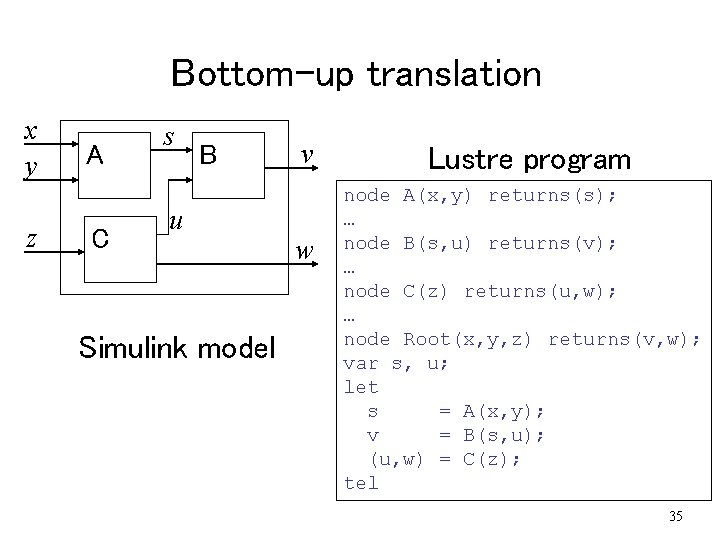
Bottom-up translation x y z A C s B u Simulink model v w Lustre program node A(x, y) returns(s); … node B(s, u) returns(v); … node C(z) returns(u, w); … node Root(x, y, z) returns(v, w); var s, u; let s = A(x, y); v = B(s, u); (u, w) = C(z); tel 35
Plan of talk • Translating Simulink to Lustre. • Distributing Lustre on TTA. • Tool-chain and case studies. 36
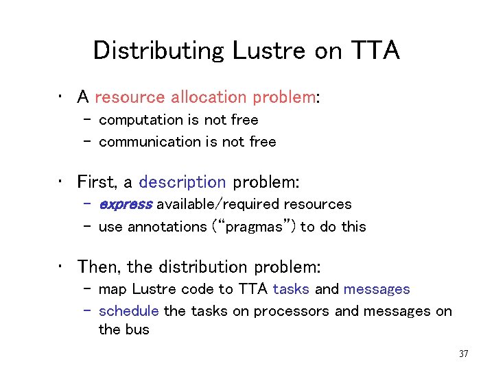
Distributing Lustre on TTA • A resource allocation problem: – computation is not free – communication is not free • First, a description problem: – express available/required resources – use annotations (“pragmas”) to do this • Then, the distribution problem: – map Lustre code to TTA tasks and messages – schedule the tasks on processors and messages on the bus 37
Distributing Lustre on TTA • Extend Lustre with annotations. • Decompose a Lustre program into tasks. • Schedule the tasks. 38
Distributing Lustre on TTA • Extend Lustre with annotations. • Decompose a Lustre program into tasks. • Schedule the tasks. 39
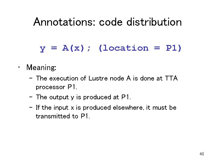
Annotations: code distribution y = A(x); (location = P 1) • Meaning: – The execution of Lustre node A is done at TTA processor P 1. – The output y is produced at P 1. – If the input x is produced elsewhere, it must be transmitted to P 1. 40
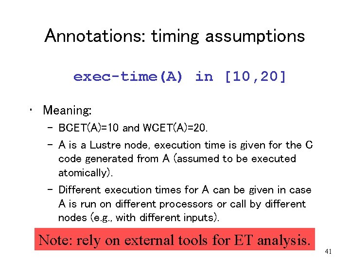
Annotations: timing assumptions exec-time(A) in [10, 20] • Meaning: – BCET(A)=10 and WCET(A)=20. – A is a Lustre node, execution time is given for the C code generated from A (assumed to be executed atomically). – Different execution times for A can be given in case A is run on different processors or call by different nodes (e. g. , with different inputs). Note: rely on external tools for ET analysis. 41
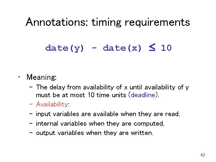
Annotations: timing requirements date(y) - date(x) 10 • Meaning: – The delay from availability of x until availability of y must be at most 10 time units (deadline). – Availability: – input variables are available when they are read, – internal variables when they are computed, – output variables when they are written. 42
Distributing Lustre on TTA • Extend Lustre with annotations. • Decompose a Lustre program into tasks. • Schedule the tasks. 43
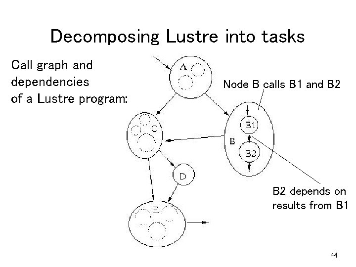
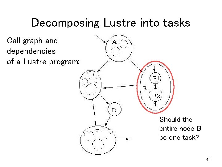
Decomposing Lustre into tasks Call graph and dependencies of a Lustre program: Node B calls B 1 and B 2 depends on results from B 1 44
Decomposing Lustre into tasks Call graph and dependencies of a Lustre program: Should the entire node B be one task? 45
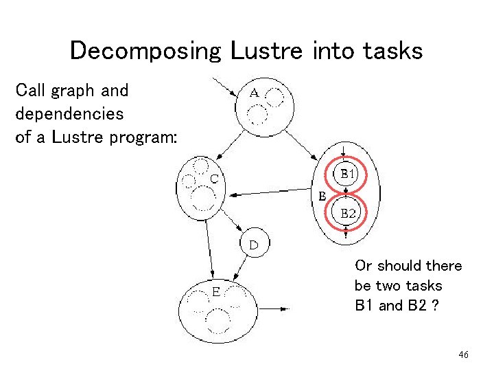
Decomposing Lustre into tasks Call graph and dependencies of a Lustre program: Or should there be two tasks B 1 and B 2 ? 46
Decomposing Lustre into tasks • Two extremes: – One task per TTA processor: too coarse, perhaps no feasible schedule (pre-emption not allowed). – One task for every Lustre operator: too fine, scheduling too costly (too many tasks). • Approach: – Start with coarse partition. – Split when necessary (no feasible schedule), based on feedback from the scheduler. – Feedback: heuristics. 47
Distributing Lustre on TTA • Extend Lustre with annotations. • Decompose a Lustre program into tasks. • Schedule the tasks. 48
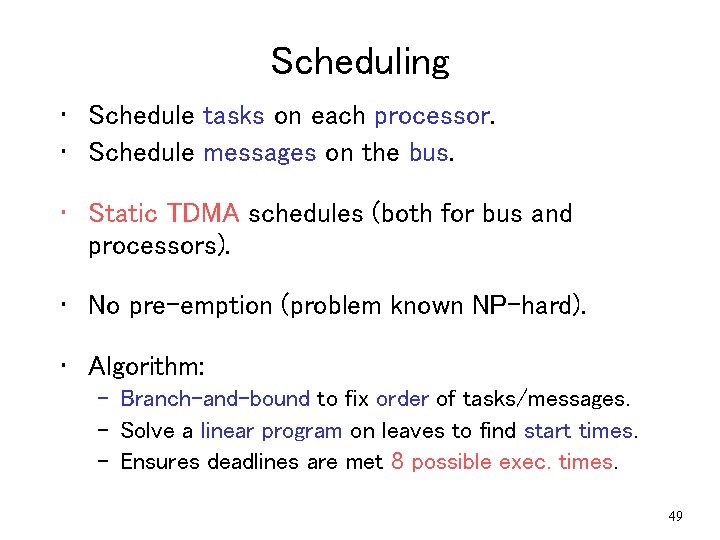
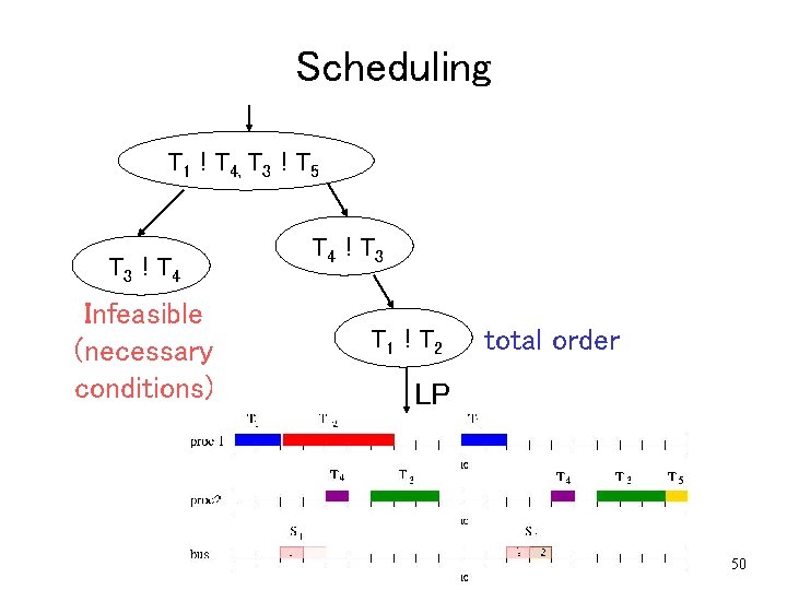
Scheduling • Schedule tasks on each processor. • Schedule messages on the bus. • Static TDMA schedules (both for bus and processors). • No pre-emption (problem known NP-hard). • Algorithm: – Branch-and-bound to fix order of tasks/messages. – Solve a linear program on leaves to find start times. – Ensures deadlines are met 8 possible exec. times. 49
Scheduling T 1 ! T 4, T 3 ! T 5 T 3 ! T 4 Infeasible (necessary conditions) T 4 ! T 3 T 1 ! T 2 total order LP 50
Plan of talk • Translating Simulink to Lustre. • Distributing Lustre on TTA. • Tool-chain and case studies. 51
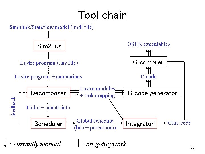
Tool chain Simulink/Stateflow model (. mdl file) Sim 2 Lus OSEK executables Lustre program (. lus file) C compiler Lustre program + annotations C code feedback Decomposer Lustre modules + task mapping C code generator Tasks + constraints Scheduler : currently manual Global schedule (bus + processors) Integrator : on-going work Glue code 52
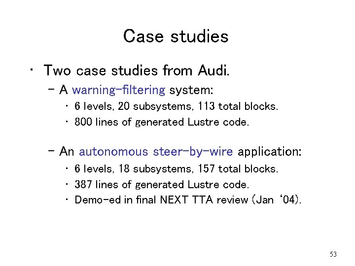
Case studies • Two case studies from Audi. – A warning-filtering system: • 6 levels, 20 subsystems, 113 total blocks. • 800 lines of generated Lustre code. – An autonomous steer-by-wire application: • 6 levels, 18 subsystems, 157 total blocks. • 387 lines of generated Lustre code. • Demo-ed in final NEXT TTA review (Jan ‘ 04). 53
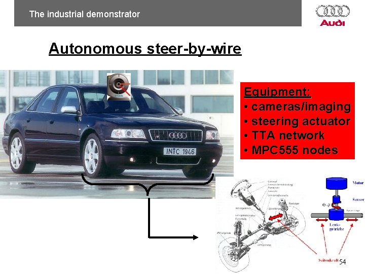
The industrial demonstrator Autonomous steer-by-wire Equipment: • cameras/imaging • steering actuator • TTA network • MPC 555 nodes 54
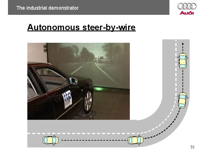
The industrial demonstrator Autonomous steer-by-wire 55
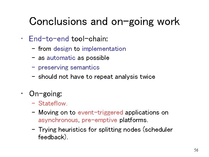
Conclusions and on-going work • End-to-end tool-chain: – – from design to implementation as automatic as possible preserving semantics should not have to repeat analysis twice • On-going: – Stateflow. – Moving on to event-triggered applications on asynchronous, pre-emptive platforms. – Trying heuristics for splitting nodes (scheduler feedback). 56
Thank you ! Questions ? 57
Two papers • “From Simulink to Lustre to TTA …”: – in “Languages, Compilers and Tools for Embedded Systems” (LCTES’ 03). • “Translating Discrete-time Simulink to Lustre”: – in “Embedded Software” (EMSOFT’ 03). 58
59