Dynamatic From CC to Dynamically Scheduled Circuits Lana

- Slides: 70
Dynamatic: From C/C++ to Dynamically Scheduled Circuits Lana Josipović, Andrea Guerrieri, and Paolo Ienne February 2020
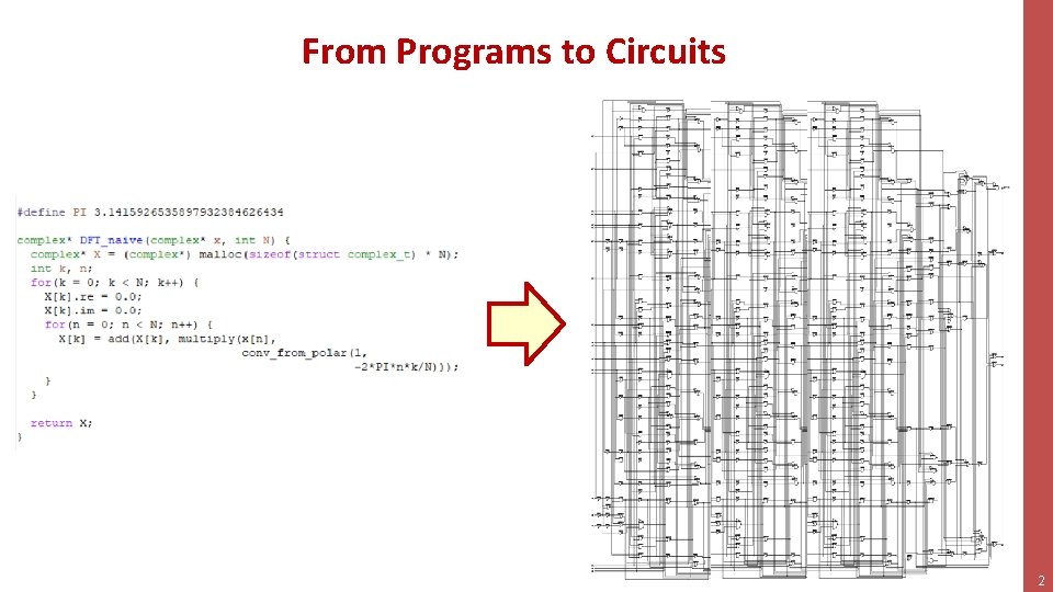
From Programs to Circuits 2
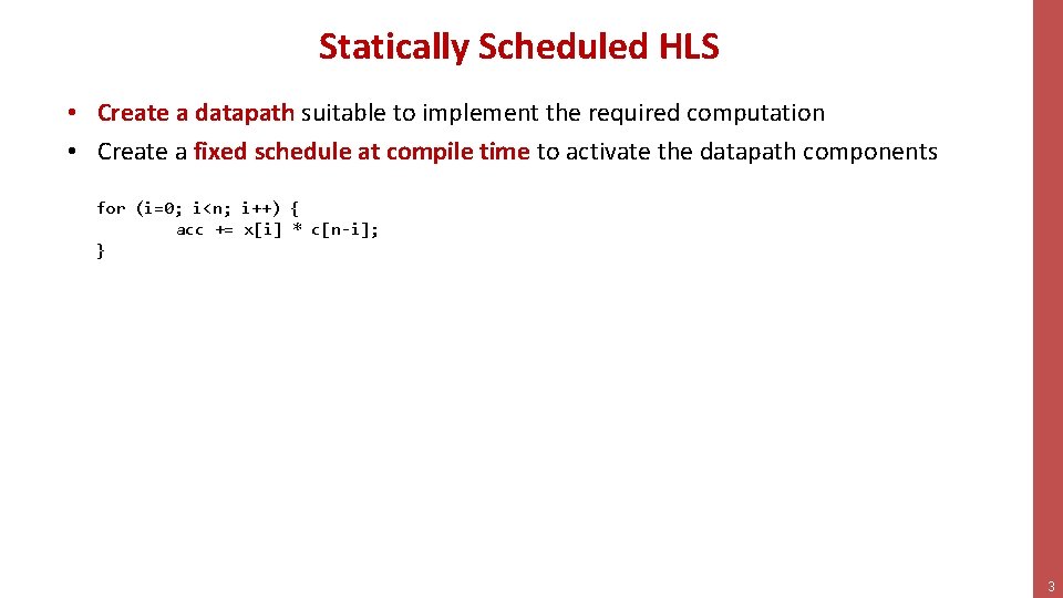
Statically Scheduled HLS • Create a datapath suitable to implement the required computation • Create a fixed schedule at compile time to activate the datapath components for (i=0; i<n; i++) { acc += x[i] * c[n-i]; } 3
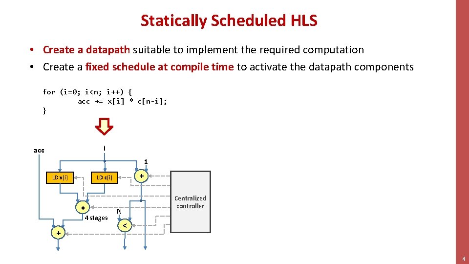
Statically Scheduled HLS • Create a datapath suitable to implement the required computation • Create a fixed schedule at compile time to activate the datapath components for (i=0; i<n; i++) { acc += x[i] * c[n-i]; } i acc 1 * 4 stages + + LD c[i] LD x[i] Centralized controller N < 4
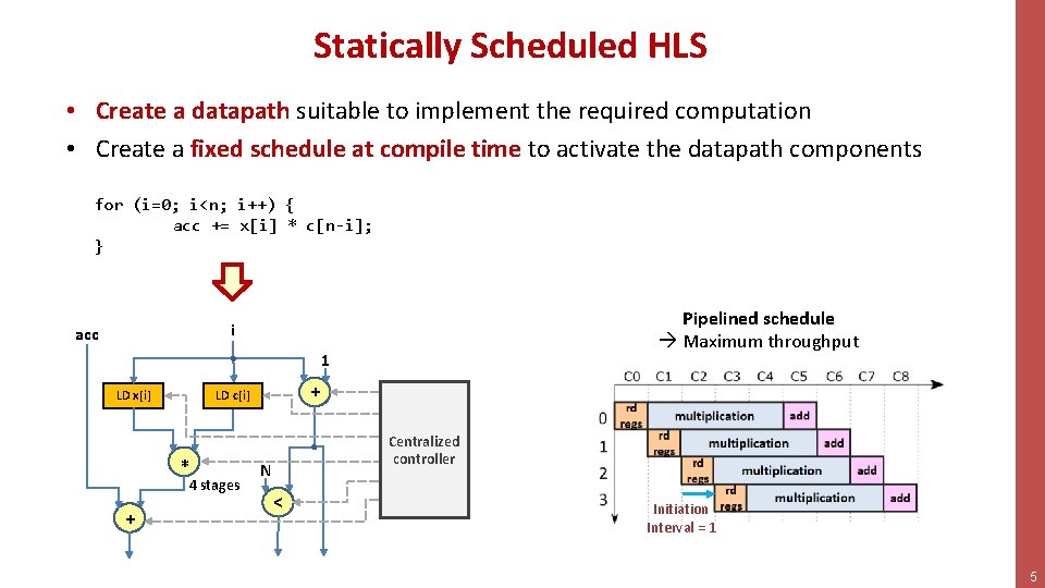
Statically Scheduled HLS • Create a datapath suitable to implement the required computation • Create a fixed schedule at compile time to activate the datapath components for (i=0; i<n; i++) { acc += x[i] * c[n-i]; } Pipelined schedule Maximum throughput i acc 1 * 4 stages + + LD c[i] LD x[i] Centralized Static controller N < Initiation Interval = 1 5
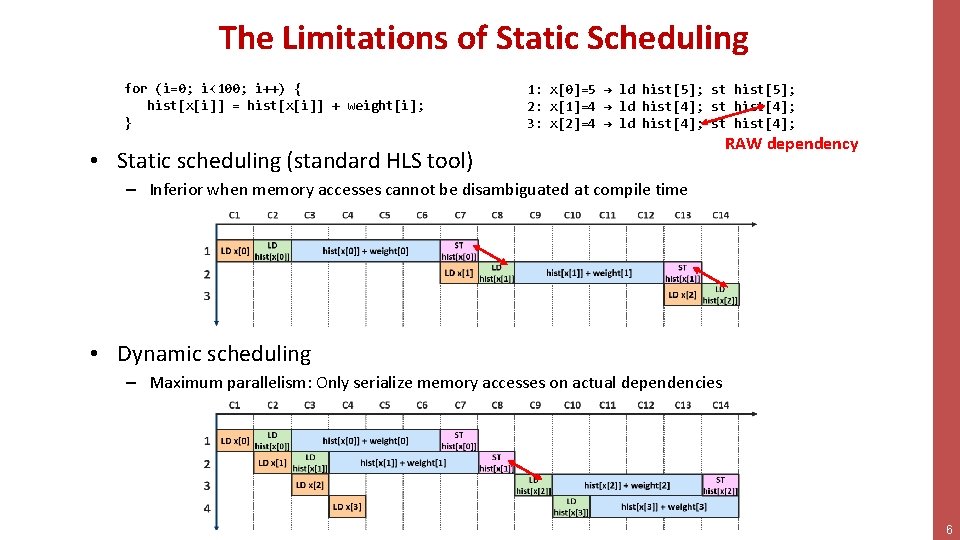
The Limitations of Static Scheduling for (i=0; i<100; i++) { hist[x[i]] = hist[x[i]] + weight[i]; } 1: x[0]=5 → ld hist[5]; st hist[5]; 2: x[1]=4 → ld hist[4]; st hist[4]; 3: x[2]=4 → ld hist[4]; st hist[4]; • Static scheduling (standard HLS tool) RAW dependency – Inferior when memory accesses cannot be disambiguated at compile time • Dynamic scheduling – Maximum parallelism: Only serialize memory accesses on actual dependencies 6
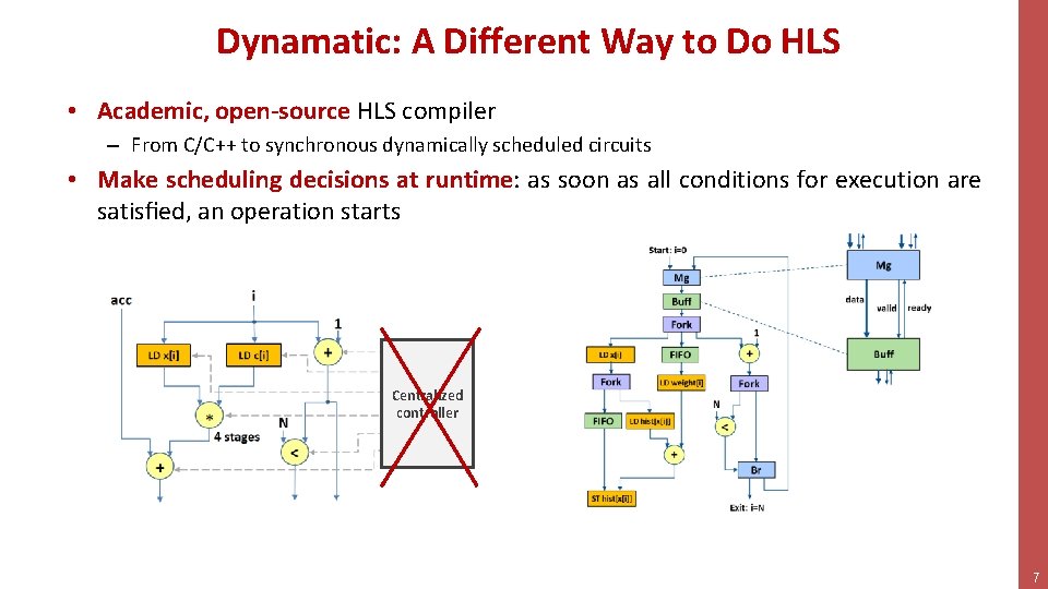
Dynamatic: A Different Way to Do HLS • Academic, open-source HLS compiler – From C/C++ to synchronous dynamically scheduled circuits • Make scheduling decisions at runtime: as soon as all conditions for execution are satisfied, an operation starts Centralized controller 7
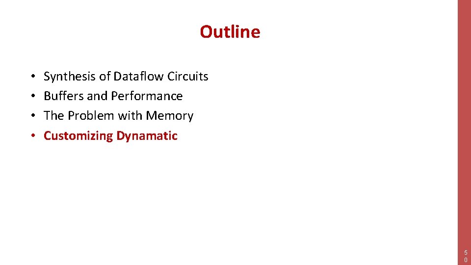
Outline • • Synthesis of Dataflow Circuits Buffers and Performance The Problem with Memory Customizing Dynamatic 8
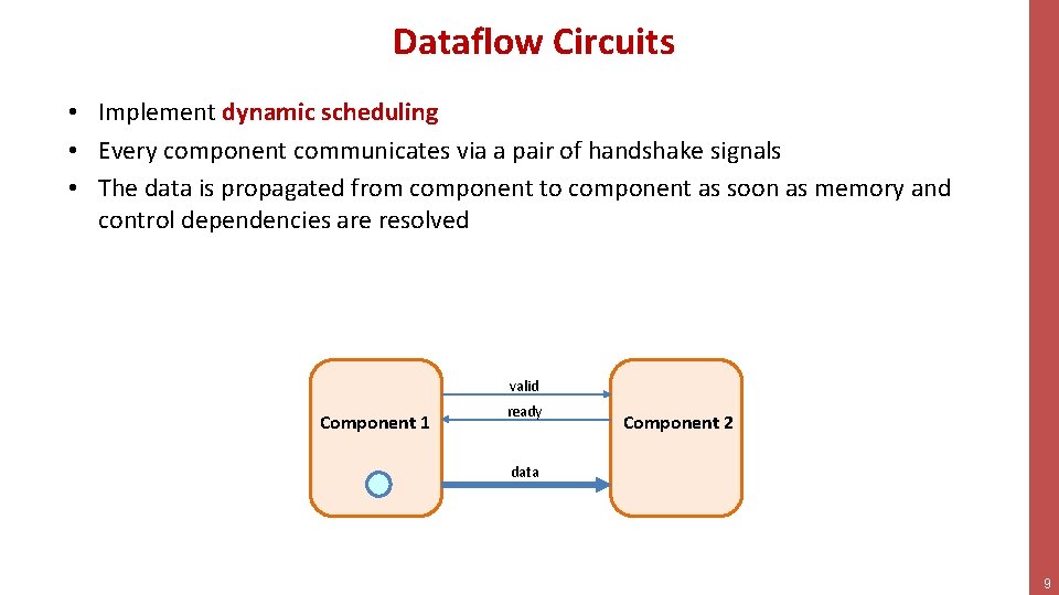
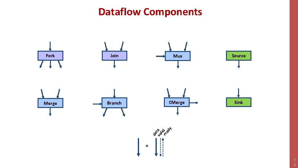
Dataflow Circuits • Implement dynamic scheduling • Every component communicates via a pair of handshake signals • The data is propagated from component to component as soon as memory and control dependencies are resolved valid Component 1 ready Component 2 data 9
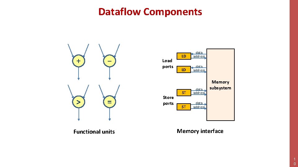
Dataflow Components + > − = Functional units Load ports Store ports LD data address ST data address Memory subsystem Memory interface 1 0
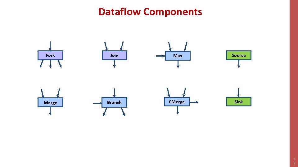
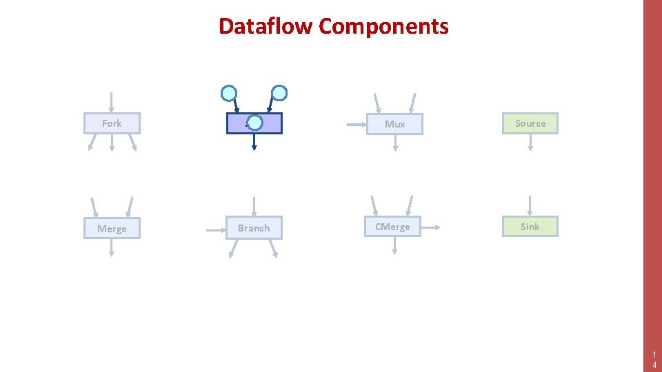
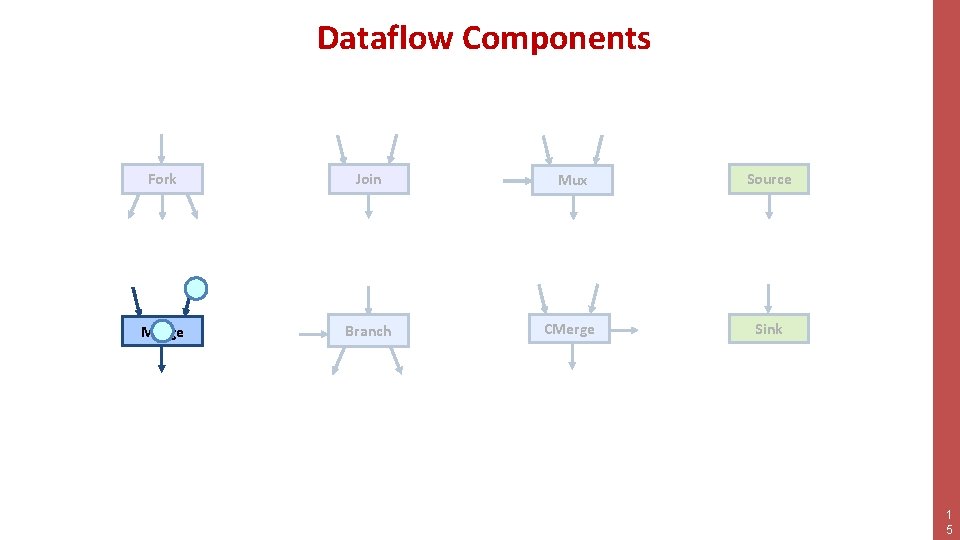
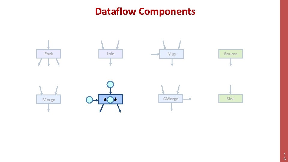
Dataflow Components Fork Join Mux Source Merge Branch CMerge Sink 1 1
Dataflow Components Join Mux Source Merge Branch CMerge Sink da va ta l re id ad y Fork = 1 2
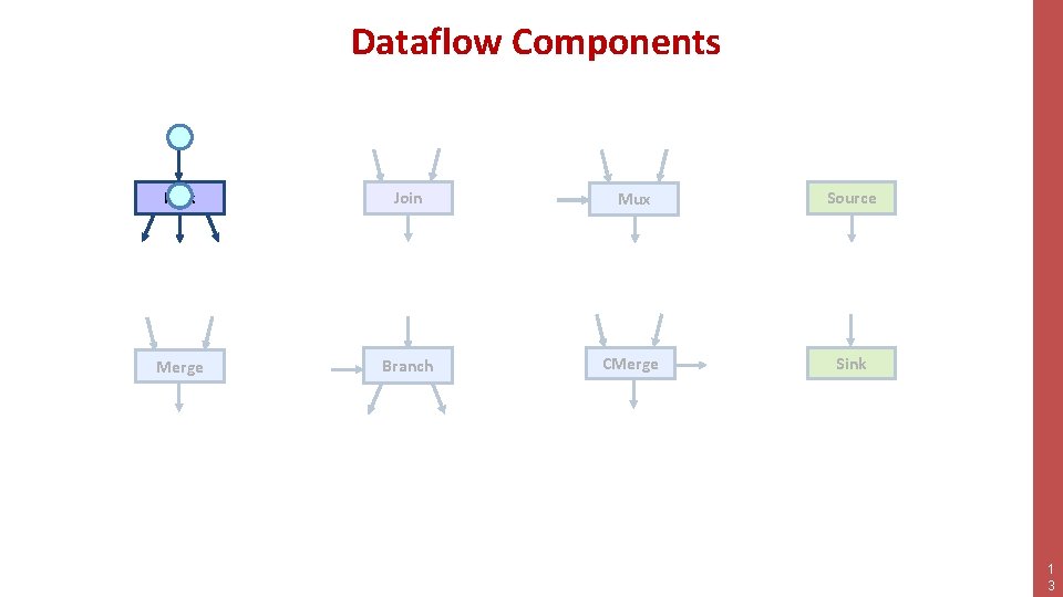
Dataflow Components Fork Join Mux Source Merge Branch CMerge Sink 1 3
Dataflow Components Fork Join Mux Source Merge Branch CMerge Sink 1 4
Dataflow Components Fork Join Mux Source Merge Branch CMerge Sink 1 5
Dataflow Components Fork Join Mux Source Merge Branch CMerge Sink 1 6
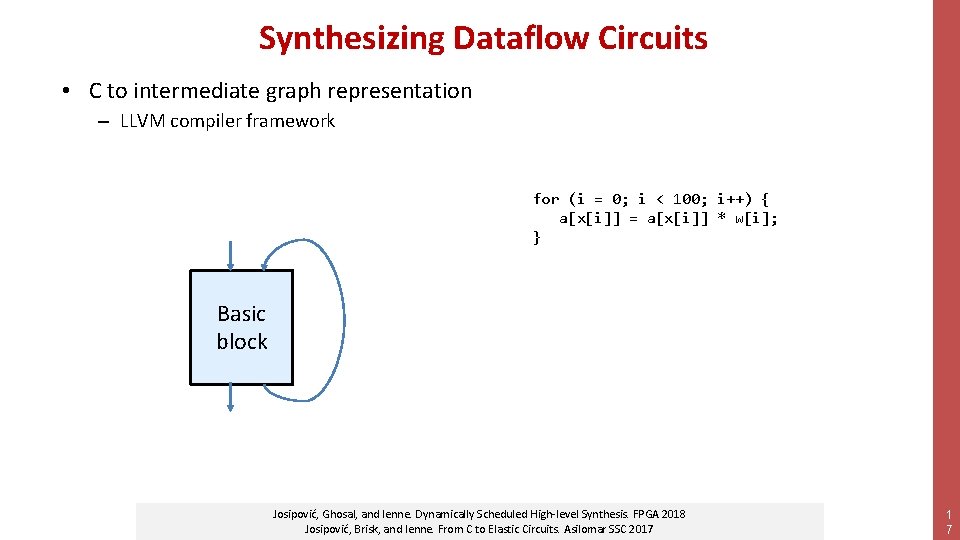
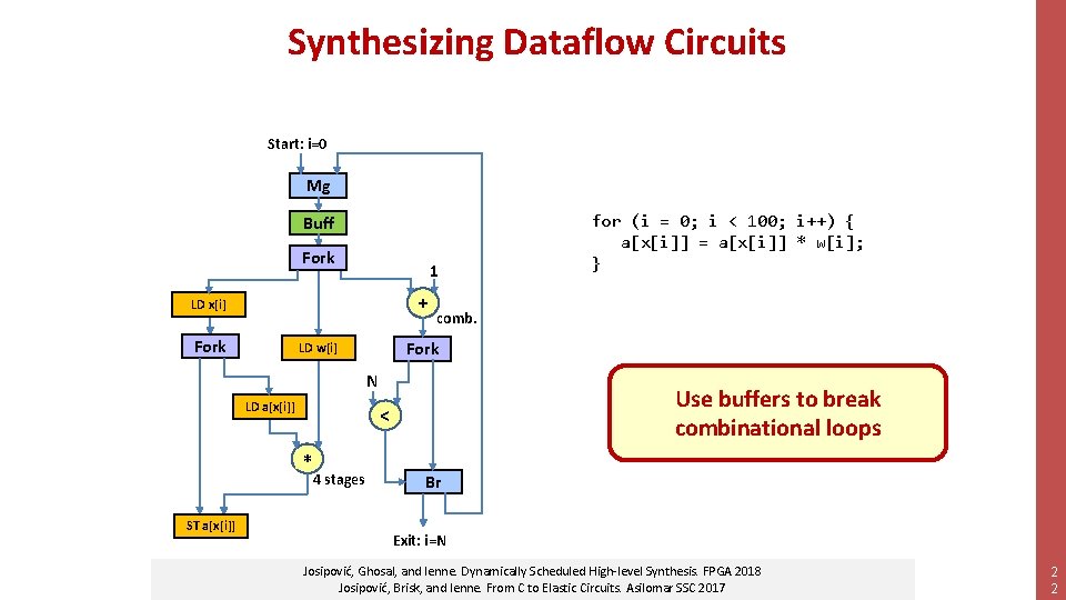
Synthesizing Dataflow Circuits • C to intermediate graph representation – LLVM compiler framework for (i = 0; i < 100; i++) { a[x[i]] = a[x[i]] * w[i]; } Basic block Josipović, Ghosal, and Ienne. Dynamically Scheduled High-level Synthesis. FPGA 2018 Josipović, Brisk, and Ienne. From C to Elastic Circuits. Asilomar SSC 2017 1 7
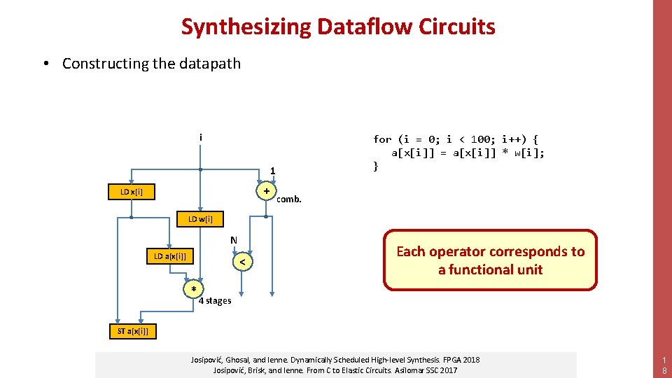
Synthesizing Dataflow Circuits • Constructing the datapath i for (i = 0; i < 100; i++) { a[x[i]] = a[x[i]] * w[i]; } 1 + LD x[i] comb. LD w[i] N LD a[x[i]] < +* Each operator corresponds to a functional unit 4 stages ST a[x[i]] Josipović, Ghosal, and Ienne. Dynamically Scheduled High-level Synthesis. FPGA 2018 Josipović, Brisk, and Ienne. From C to Elastic Circuits. Asilomar SSC 2017 1 8
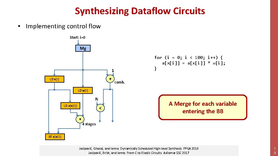
Synthesizing Dataflow Circuits • Implementing control flow Start: i=0 Mg for (i = 0; i < 100; i++) { a[x[i]] = a[x[i]] * w[i]; } 1 + LD x[i] comb. LD w[i] N LD a[x[i]] < +* A Merge for each variable entering the BB 4 stages ST a[x[i]] Josipović, Ghosal, and Ienne. Dynamically Scheduled High-level Synthesis. FPGA 2018 Josipović, Brisk, and Ienne. From C to Elastic Circuits. Asilomar SSC 2017 1 9
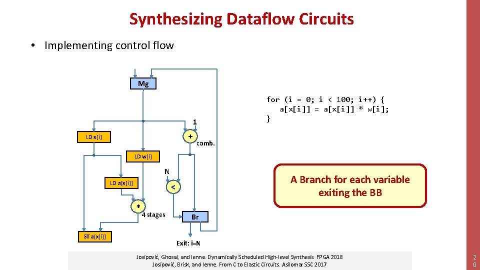
Synthesizing Dataflow Circuits • Implementing control flow Mg 1 + LD x[i] for (i = 0; i < 100; i++) { a[x[i]] = a[x[i]] * w[i]; } comb. LD w[i] N LD a[x[i]] +* ST a[x[i]] A Branch for each variable exiting the BB < 4 stages Br Exit: i=N Josipović, Ghosal, and Ienne. Dynamically Scheduled High-level Synthesis. FPGA 2018 Josipović, Brisk, and Ienne. From C to Elastic Circuits. Asilomar SSC 2017 2 0
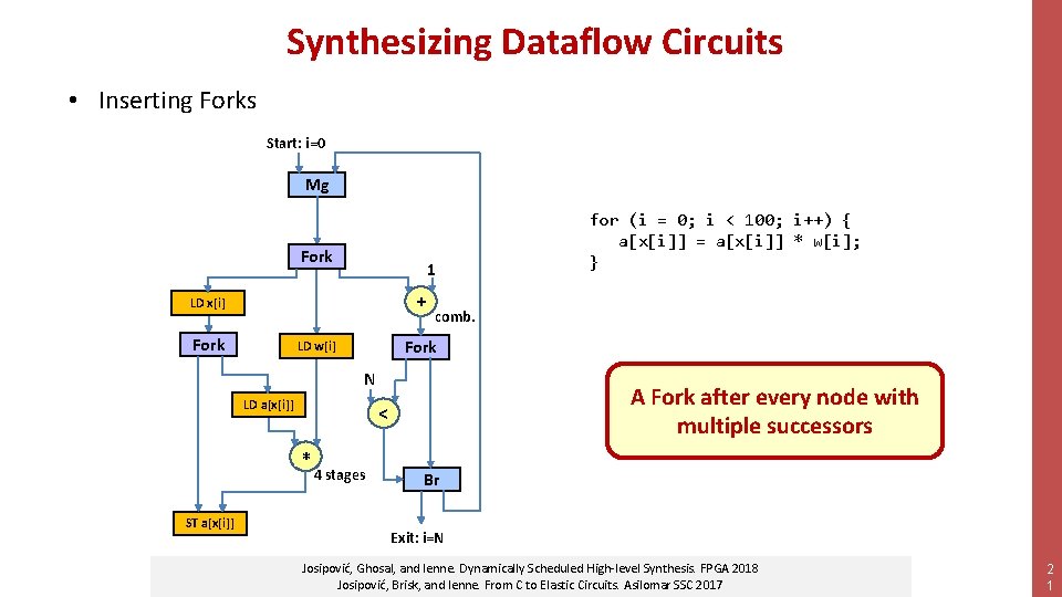
Synthesizing Dataflow Circuits • Inserting Forks Start: i=0 Mg Fork 1 + LD x[i] Fork comb. Fork LD w[i] N LD a[x[i]] ST a[x[i]] A Fork after every node with multiple successors < +* for (i = 0; i < 100; i++) { a[x[i]] = a[x[i]] * w[i]; } 4 stages Br Exit: i=N Josipović, Ghosal, and Ienne. Dynamically Scheduled High-level Synthesis. FPGA 2018 Josipović, Brisk, and Ienne. From C to Elastic Circuits. Asilomar SSC 2017 2 1
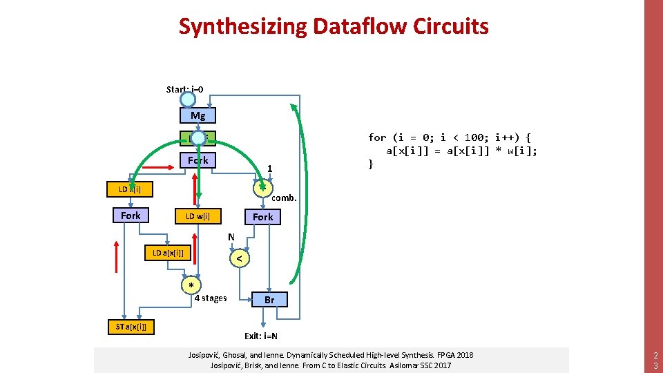
Synthesizing Dataflow Circuits Start: i=0 Mg Buff Fork 1 + LD x[i] Fork comb. Fork LD w[i] N LD a[x[i]] STSThist[x[i]] a[x[i]] Use buffers to break combinational loops < *+ 4 stages for (i = 0; i < 100; i++) { a[x[i]] = a[x[i]] * w[i]; } Br Exit: i=N Josipović, Ghosal, and Ienne. Dynamically Scheduled High-level Synthesis. FPGA 2018 Josipović, Brisk, and Ienne. From C to Elastic Circuits. Asilomar SSC 2017 2 2
Synthesizing Dataflow Circuits Start: i=0 Mg Buff Fork 1 + LD x[i] Fork for (i = 0; i < 100; i++) { a[x[i]] = a[x[i]] * w[i]; } comb. Fork LD w[i] N LD a[x[i]] < *+ STSThist[x[i]] a[x[i]] 4 stages Br Exit: i=N Josipović, Ghosal, and Ienne. Dynamically Scheduled High-level Synthesis. FPGA 2018 Josipović, Brisk, and Ienne. From C to Elastic Circuits. Asilomar SSC 2017 2 3
Exercise 1: Synthesis • Synthesize the example kernel in C into a dataflow circuit – ‘Naïve’ translation • Study the outputs – Graphical representation and RTL netlist • Analyze performance & check correctness – RTL simulation execution time – Result comparison with software simulation 2 4
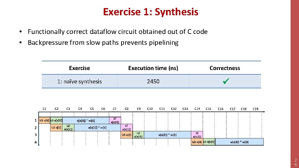
Exercise 1: Synthesis • Functionally correct dataflow circuit obtained out of C code • Backpressure from slow paths prevents pipelining Exercise Execution time (ns) Correctness 1: naïve synthesis 2450 2 5
Outline • • Synthesis of Dataflow Circuits Buffers and Performance The Problem with Memory Customizing Dynamatic 2 6
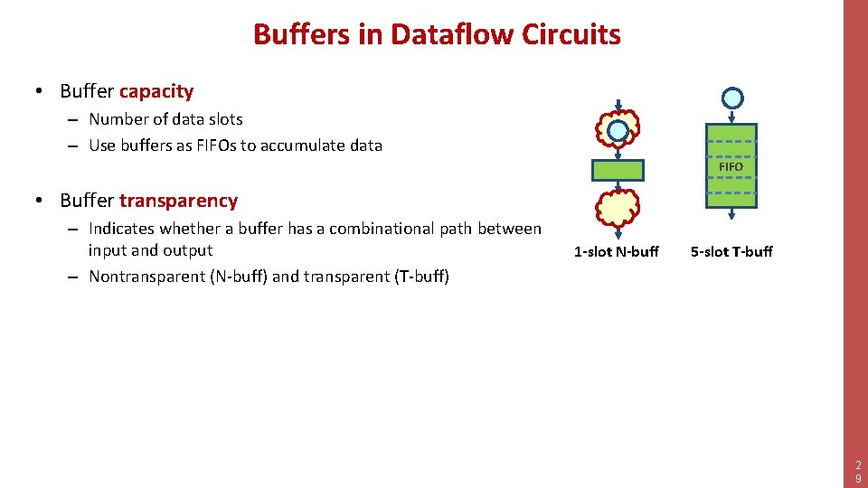
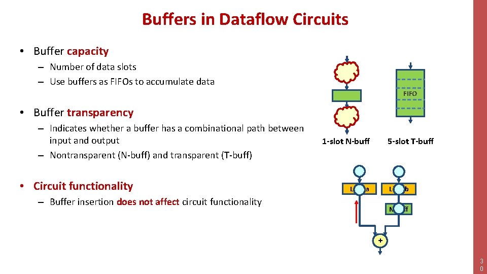
Buffers in Dataflow Circuits • Buffer capacity – Number of data slots – Use buffers as FIFOs to accumulate data 2 7
Buffers in Dataflow Circuits • Buffer capacity – Number of data slots – Use buffers as FIFOs to accumulate data • Buffer transparency – Indicates whether a buffer has a combinational path between input and output – Nontransparent (N-buff) and transparent (T-buff) 2 8
Buffers in Dataflow Circuits • Buffer capacity – Number of data slots – Use buffers as FIFOs to accumulate data FIFO • Buffer transparency – Indicates whether a buffer has a combinational path between input and output – Nontransparent (N-buff) and transparent (T-buff) 1 -slot N-buff 5 -slot T-buff 2 9
Buffers in Dataflow Circuits • Buffer capacity – Number of data slots – Use buffers as FIFOs to accumulate data FIFO • Buffer transparency – Indicates whether a buffer has a combinational path between input and output – Nontransparent (N-buff) and transparent (T-buff) • Circuit functionality 1 -slot N-buff 5 -slot T-buff Load a Load b – Buffer insertion does not affect circuit functionality N-buff + 3 0
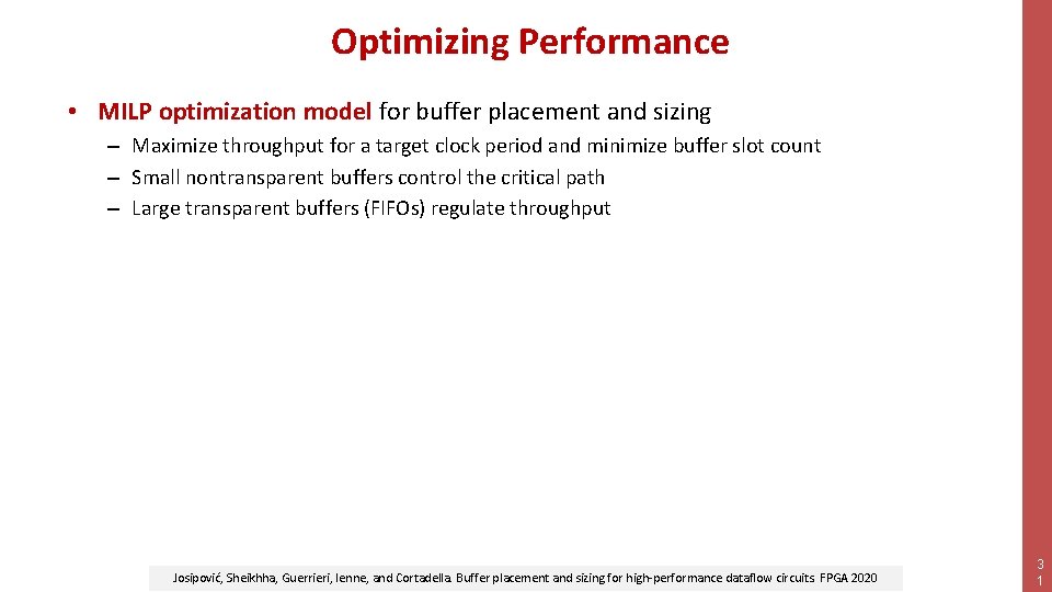
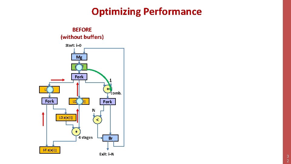
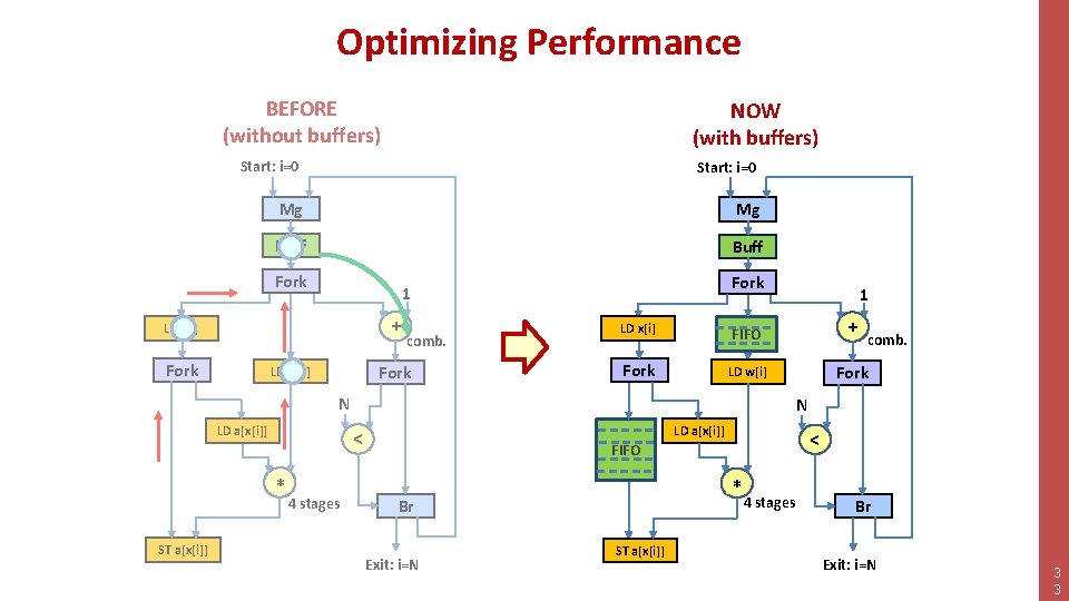
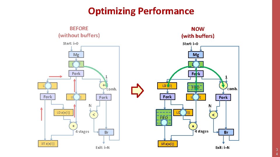
Optimizing Performance • MILP optimization model for buffer placement and sizing – Maximize throughput for a target clock period and minimize buffer slot count – Small nontransparent buffers control the critical path – Large transparent buffers (FIFOs) regulate throughput Josipović, Sheikhha, Guerrieri, Ienne, and Cortadella. Buffer placement and sizing for high-performance dataflow circuits. FPGA 2020 3 1
Optimizing Performance BEFORE (without buffers) Start: i=0 Mg Buff Fork 1 + LD x[i] Fork comb. Fork LD we[i] N LD a[x[i]] < *+ ST a[x[i]] 4 stages Br Exit: i=N 3 2
Optimizing Performance BEFORE (without buffers) NOW (with buffers) Start: i=0 Mg Mg Buff Fork + LD x[i] Fork 1 comb. Fork LD w[i] LD x[i] FIFO + Fork LD w[i] Fork N LD a[x[i]] ST a[x[i]] 4 stages comb. N FIFO < *+ 1 LD a[x[i]] < FIFO +* Br Exit: i=N ST a[x[i]] 4 stages Br Exit: i=N 3 3
Optimizing Performance BEFORE (without buffers) NOW (with buffers) Start: i=0 Mg Mg Buff Fork + LD x[i] Fork 1 comb. Fork LD w[i] LD x[i] FIFO + Fork LD w[i] Fork N LD a[x[i]] ST a[x[i]] 4 stages comb. N FIFO < *+ 1 LD a[x[i]] < FIFO +* Br Exit: i=N ST a[x[i]] 4 stages Br Exit: i=N 3 4
Exercise 2: Adding Buffers • Synthesize the example kernel in C into a dataflow circuit – ‘Naïve’ translation • Optimize performance – Buffer placement and sizing • Study the outputs – Graphical representation and RTL netlist • Analyze performance & check correctness – RTL simulation execution time – Result comparison with software simulation 3 5
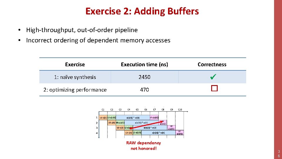
Exercise 2: Adding Buffers • High-throughput, out-of-order pipeline • Incorrect ordering of dependent memory accesses Exercise Execution time (ns) 1: naïve synthesis 2450 2: optimizing performance 470 RAW dependency not honored! Correctness � 3 6
Outline • • Synthesis of Dataflow Circuits Buffers and Performance The Problem with Memory Customizing Dynamatic 3 7
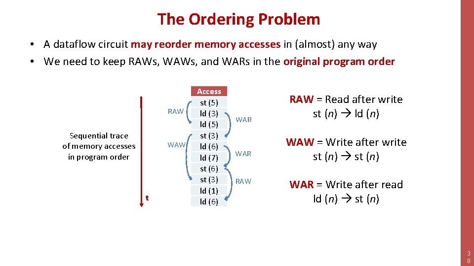
The Ordering Problem • A dataflow circuit may reorder memory accesses in (almost) any way • We need to keep RAWs, WAWs, and WARs in the original program order RAW Sequential trace of memory accesses in program order WAW t Access st (5) ld (3) ld (5) st (3) ld (6) ld (7) st (6) st (3) ld (1) ld (6) WAR RAW = Read after write st (n) ld (n) WAW = Write after write st (n) WAR = Write after read ld (n) st (n) 3 8
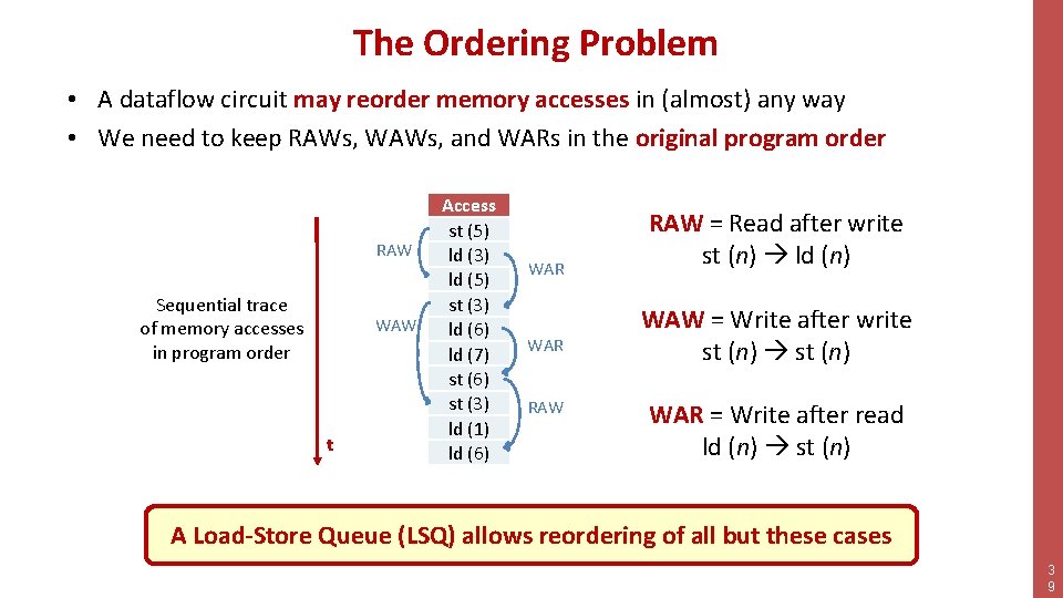
The Ordering Problem • A dataflow circuit may reorder memory accesses in (almost) any way • We need to keep RAWs, WAWs, and WARs in the original program order RAW Sequential trace of memory accesses in program order WAW t Access st (5) ld (3) ld (5) st (3) ld (6) ld (7) st (6) st (3) ld (1) ld (6) WAR RAW = Read after write st (n) ld (n) WAW = Write after write st (n) WAR = Write after read ld (n) st (n) A Load-Store Queue (LSQ) allows reordering of all but these cases 3 9
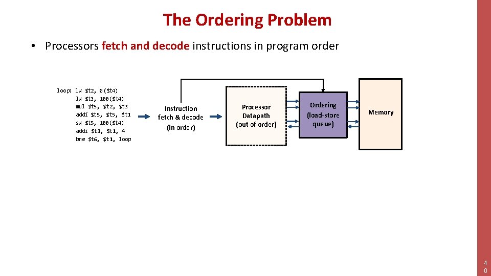
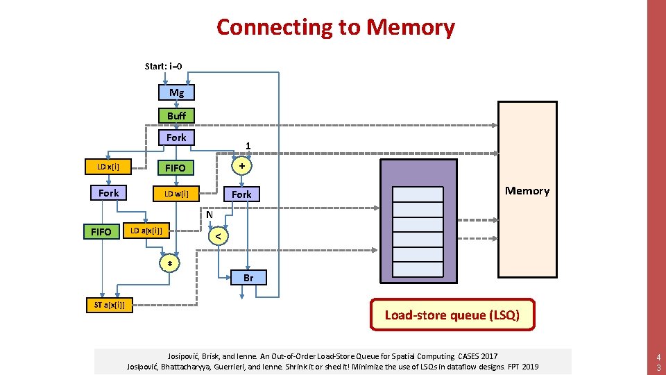
The Ordering Problem • Processors fetch and decode instructions in program order loop: lw $t 2, 0($t 4) lw $t 3, 100($t 4) mul $t 5, $t 2, $t 3 addi $t 5, $t 1 sw $t 5, 100($t 4) addi $t 1, 4 bne $t 6, $t 1, loop Instruction fetch & decode (in order) Processor Datapath (out of order) Ordering (load-store queue) Memory 4 0
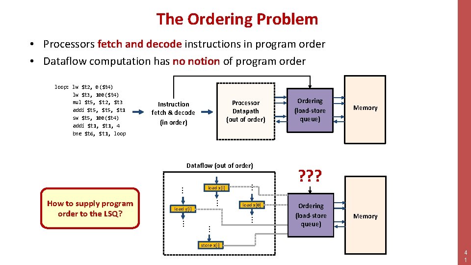
The Ordering Problem • Processors fetch and decode instructions in program order • Dataflow computation has no notion of program order loop: lw $t 2, 0($t 4) lw $t 3, 100($t 4) mul $t 5, $t 2, $t 3 addi $t 5, $t 1 sw $t 5, 100($t 4) addi $t 1, 4 bne $t 6, $t 1, loop Processor Datapath (out of order) Instruction fetch & decode (in order) Dataflow (out of order) … load y[i] … … load x[0] … … … How to supply program order to the LSQ? load x[i] Ordering (load-store queue) Memory ? ? ? Ordering (load-store queue) Memory store x[i] 4 1
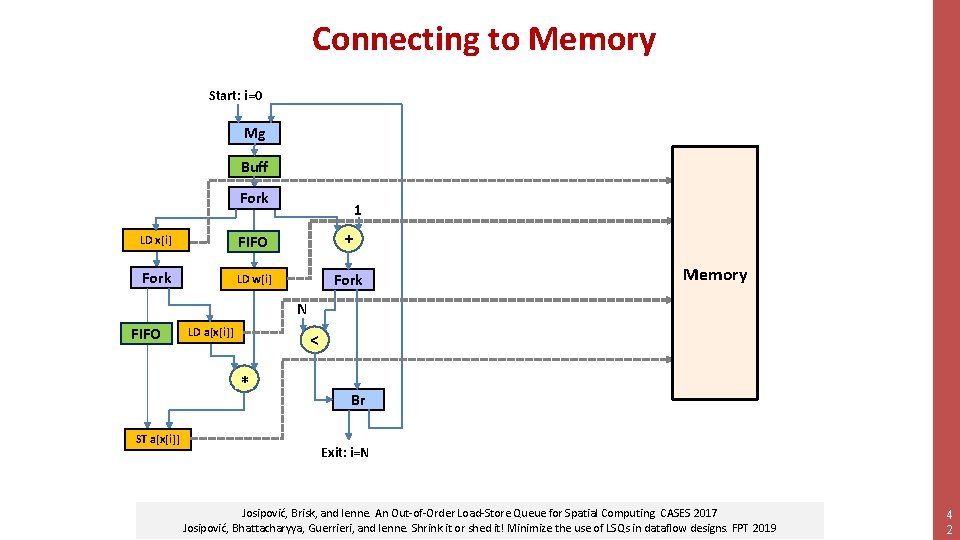
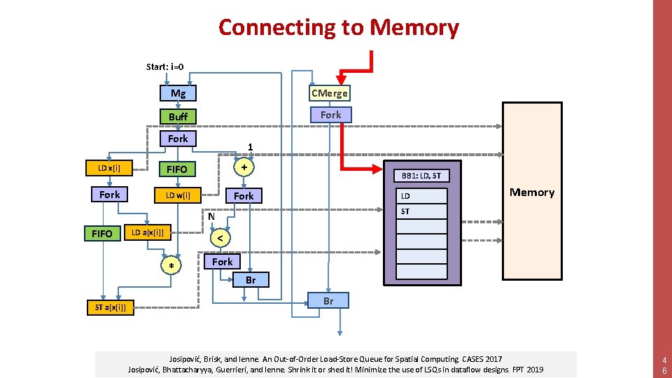
Connecting to Memory Start: i=0 Mg Buff Fork 1 LD x[i] FIFO + Fork LD w[i] Fork Memory N FIFO LD a[x[i]] < +* STSThist[x[i]] a[x[i]] Br Exit: i=N Josipović, Brisk, and Ienne. An Out-of-Order Load-Store Queue for Spatial Computing. CASES 2017 Josipović, Bhattacharyya, Guerrieri, and Ienne. Shrink it or shed it! Minimize the use of LSQs in dataflow designs. FPT 2019 4 2
Connecting to Memory Start: i=0 Mg Buff Fork 1 LD x[i] FIFO + Fork LD w[i] Fork LD a[x[i]] STSThist[x[i]] a[x[i]] LD a 3 < +* Memory ST a 2 N FIFO LD a 1 ST a 4 Br Load-store queue (LSQ) Josipović, Brisk, and Ienne. An Out-of-Order Load-Store Queue for Spatial Computing. CASES 2017 Josipović, Bhattacharyya, Guerrieri, and Ienne. Shrink it or shed it! Minimize the use of LSQs in dataflow designs. FPT 2019 4 3
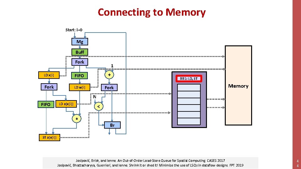
Connecting to Memory Start: i=0 Mg Buff Fork 1 LD x[i] FIFO + Fork LD w[i] Fork LD a[x[i]] Memory LD a 3 < +* LD a 1 ST a 2 N FIFO BB 1: LD, ST ST a 4 Br STSThist[x[i]] a[x[i]] Josipović, Brisk, and Ienne. An Out-of-Order Load-Store Queue for Spatial Computing. CASES 2017 Josipović, Bhattacharyya, Guerrieri, and Ienne. Shrink it or shed it! Minimize the use of LSQs in dataflow designs. FPT 2019 4 4
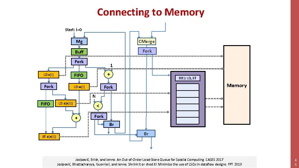
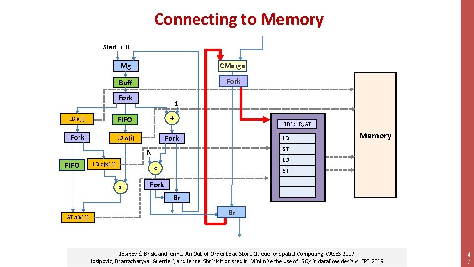
Connecting to Memory Start: i=0 Mg CMerge Buff Fork 1 LD x[i] FIFO + Fork LD w[i] Fork BB 1: LD, ST LD a 1 ST a 2 N FIFO LD a[x[i]] STSThist[x[i]] a[x[i]] LD a 3 < +* Memory ST a 4 Fork Br Br Josipović, Brisk, and Ienne. An Out-of-Order Load-Store Queue for Spatial Computing. CASES 2017 Josipović, Bhattacharyya, Guerrieri, and Ienne. Shrink it or shed it! Minimize the use of LSQs in dataflow designs. FPT 2019 4 5
Connecting to Memory Start: i=0 Mg CMerge Buff Fork 1 LD x[i] FIFO + Fork LD w[i] Fork BB 1: LD, ST LD a 1 ST a 2 N FIFO LD a[x[i]] STSThist[x[i]] a[x[i]] LD a 3 < +* Memory ST a 4 Fork Br Br Josipović, Brisk, and Ienne. An Out-of-Order Load-Store Queue for Spatial Computing. CASES 2017 Josipović, Bhattacharyya, Guerrieri, and Ienne. Shrink it or shed it! Minimize the use of LSQs in dataflow designs. FPT 2019 4 6
Connecting to Memory Start: i=0 Mg CMerge Buff Fork 1 LD x[i] FIFO + Fork LD w[i] Fork BB 1: LD, ST LD a 1 ST a 2 N FIFO LD a[x[i]] STSThist[x[i]] a[x[i]] LD a 3 < +* Memory ST a 4 Fork Br Br Josipović, Brisk, and Ienne. An Out-of-Order Load-Store Queue for Spatial Computing. CASES 2017 Josipović, Bhattacharyya, Guerrieri, and Ienne. Shrink it or shed it! Minimize the use of LSQs in dataflow designs. FPT 2019 4 7
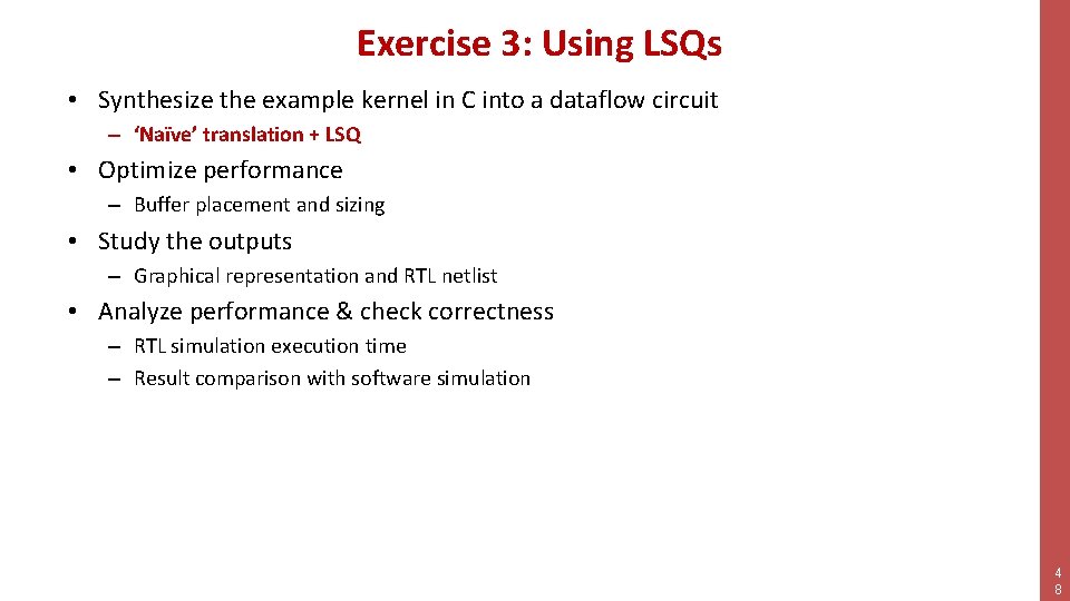
Exercise 3: Using LSQs • Synthesize the example kernel in C into a dataflow circuit – ‘Naïve’ translation + LSQ • Optimize performance – Buffer placement and sizing • Study the outputs – Graphical representation and RTL netlist • Analyze performance & check correctness – RTL simulation execution time – Result comparison with software simulation 4 8
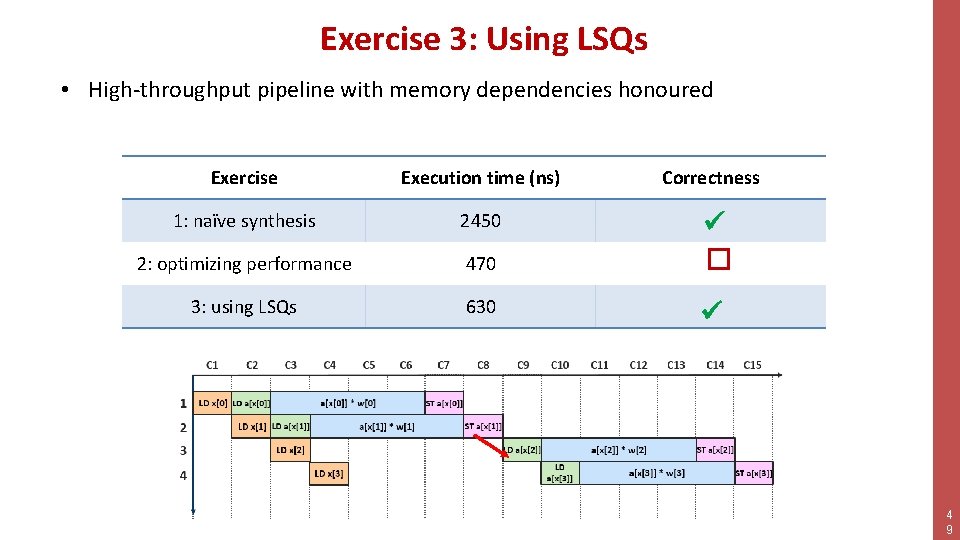
Exercise 3: Using LSQs • High-throughput pipeline with memory dependencies honoured Exercise Execution time (ns) Correctness 1: naïve synthesis 2450 2: optimizing performance 470 � 3: using LSQs 630 4 9
Outline • • Synthesis of Dataflow Circuits Buffers and Performance The Problem with Memory Customizing Dynamatic 5 0
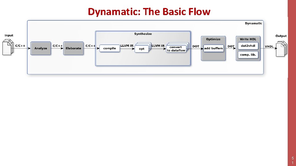
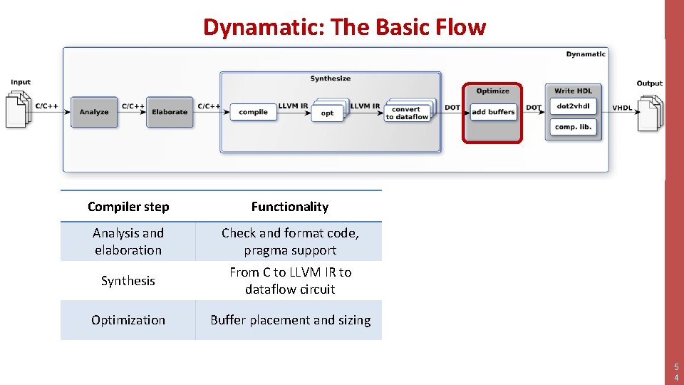
Dynamatic: The Basic Flow 5 1
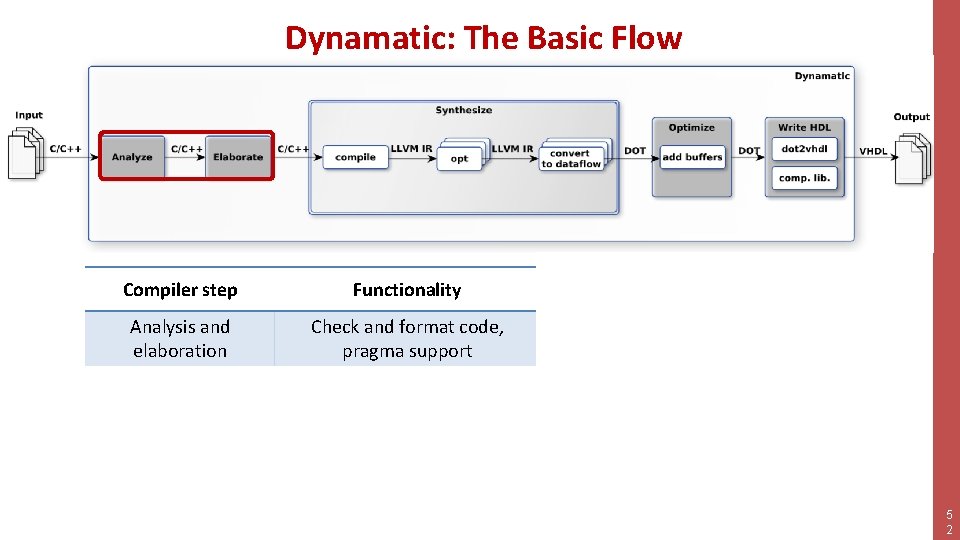
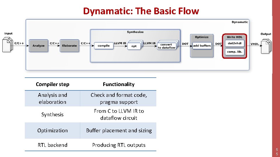
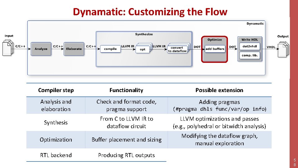
Dynamatic: The Basic Flow Compiler step Functionality Possible extension Analysis and elaboration Check and format code, pragma support Adding pragmas Synthesis From C to LLVM IR to dataflow circuit LLVM optimizations and passes (e. g. , polyhedral or bitwidth analysis) Optimization Buffer placement and sizing Modifying the dataflow graph, manual exploration RTL backend Producing RTL outputs Adding custom components 5 2
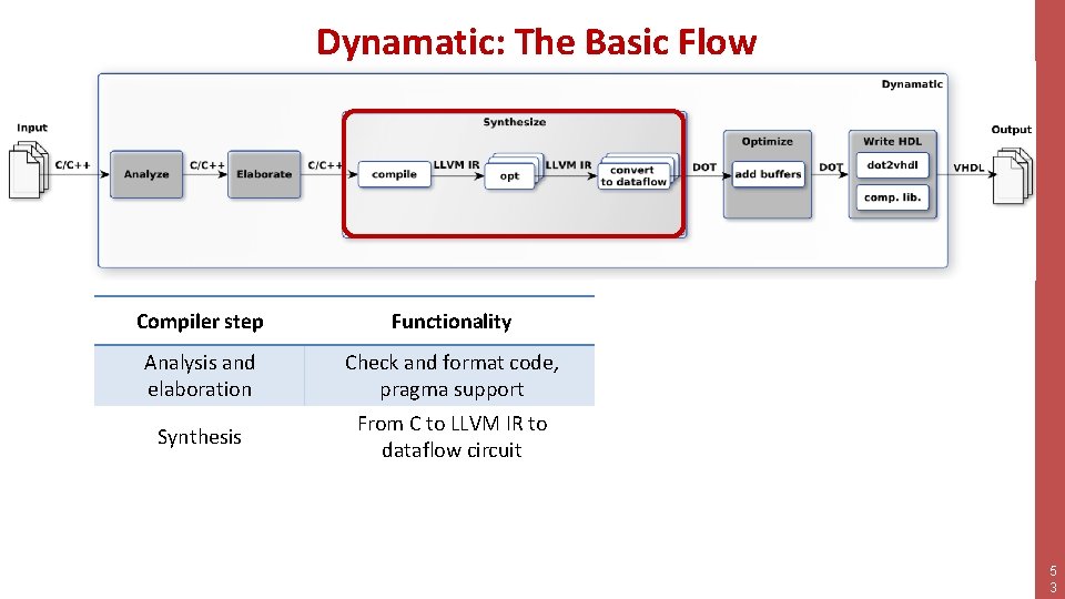
Dynamatic: The Basic Flow Compiler step Functionality Possible extension Analysis and elaboration Check and format code, pragma support Adding pragmas Synthesis From C to LLVM IR to dataflow circuit LLVM optimizations and passes (e. g. , polyhedral or bitwidth analysis) Optimization Buffer placement and sizing Modifying the dataflow graph, manual exploration RTL backend Producing RTL outputs Adding custom components 5 3
Dynamatic: The Basic Flow Compiler step Functionality Possible extension Analysis and elaboration Check and format code, pragma support Adding pragmas Synthesis From C to LLVM IR to dataflow circuit LLVM optimizations and passes (e. g. , polyhedral or bitwidth analysis) Optimization Buffer placement and sizing Modifying the dataflow graph, manual exploration RTL backend Producing RTL outputs Adding custom components 5 4
Dynamatic: The Basic Flow Compiler step Functionality Possible extension Analysis and elaboration Check and format code, pragma support Adding pragmas Synthesis From C to LLVM IR to dataflow circuit LLVM optimizations and passes (e. g. , polyhedral or bitwidth analysis) Optimization Buffer placement and sizing Modifying the dataflow graph, manual exploration RTL backend Producing RTL outputs Adding custom components 5 5
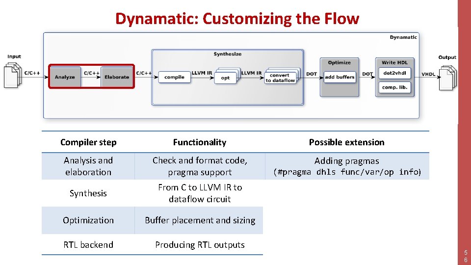
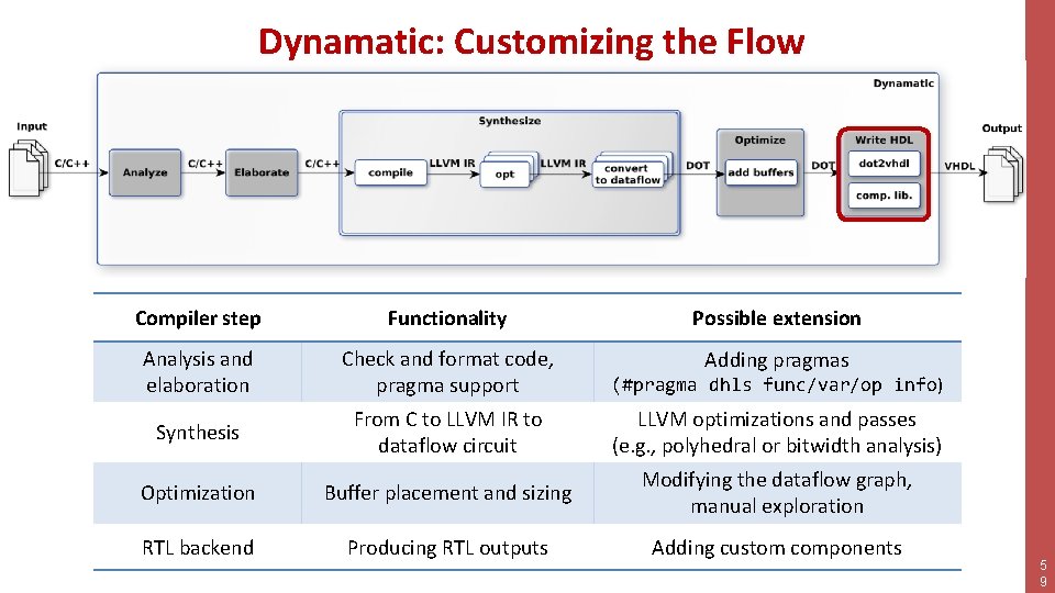
Dynamatic: Customizing the Flow Compiler step Functionality Possible extension Analysis and elaboration Check and format code, pragma support Adding pragmas (#pragma dhls func/var/op info) Synthesis From C to LLVM IR to dataflow circuit LLVM optimizations and passes (e. g. , polyhedral or bitwidth analysis) Optimization Buffer placement and sizing Modifying the dataflow graph, manual exploration RTL backend Producing RTL outputs Adding custom components 5 6
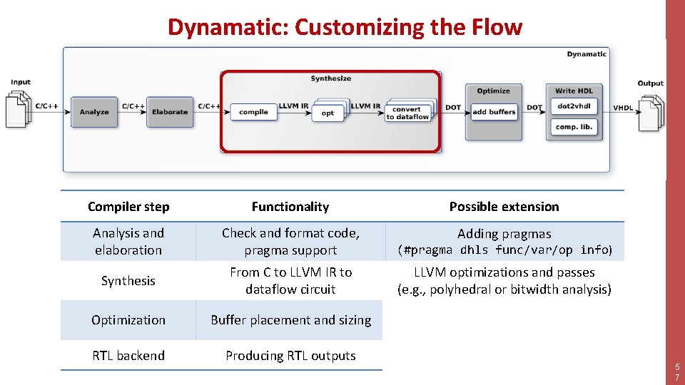
Dynamatic: Customizing the Flow Compiler step Functionality Possible extension Analysis and elaboration Check and format code, pragma support Adding pragmas (#pragma dhls func/var/op info) Synthesis From C to LLVM IR to dataflow circuit LLVM optimizations and passes (e. g. , polyhedral or bitwidth analysis) Optimization Buffer placement and sizing Modifying the dataflow graph, manual exploration RTL backend Producing RTL outputs Adding custom components 5 7
Dynamatic: Customizing the Flow Compiler step Functionality Possible extension Analysis and elaboration Check and format code, pragma support Adding pragmas (#pragma dhls func/var/op info) Synthesis From C to LLVM IR to dataflow circuit LLVM optimizations and passes (e. g. , polyhedral or bitwidth analysis) Optimization Buffer placement and sizing Modifying the dataflow graph, manual exploration RTL backend Producing RTL outputs Adding custom components 5 8
Dynamatic: Customizing the Flow Compiler step Functionality Possible extension Analysis and elaboration Check and format code, pragma support Adding pragmas (#pragma dhls func/var/op info) Synthesis From C to LLVM IR to dataflow circuit LLVM optimizations and passes (e. g. , polyhedral or bitwidth analysis) Optimization Buffer placement and sizing Modifying the dataflow graph, manual exploration RTL backend Producing RTL outputs Adding custom components 5 9
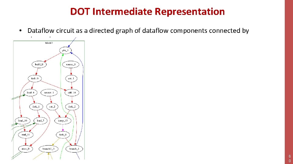
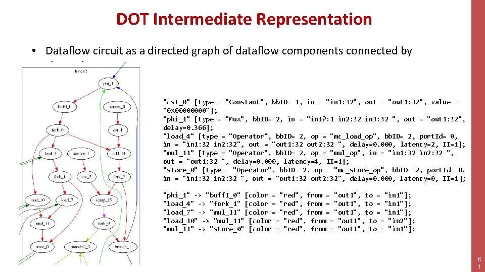
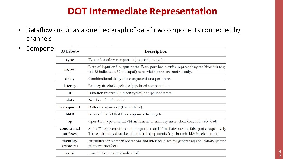
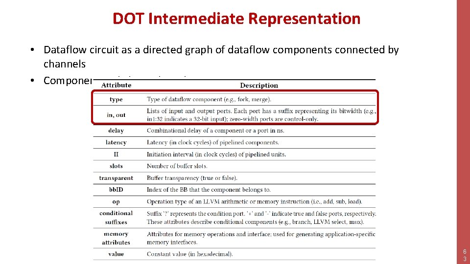
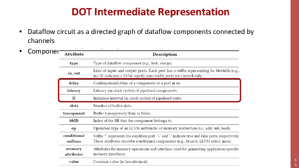
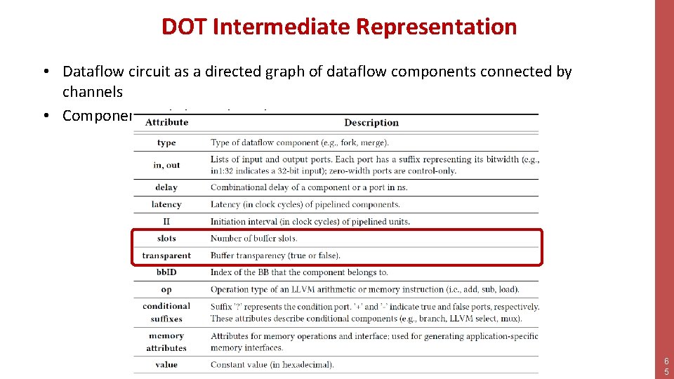
DOT Intermediate Representation • Dataflow circuit as a directed graph of dataflow components connected by channels 6 0
DOT Intermediate Representation • Dataflow circuit as a directed graph of dataflow components connected by channels "cst_0" [type = "Constant", bb. ID= 1, in = "in 1: 32", out = "out 1: 32", value = "0 x 0000"]; "phi_1" [type = "Mux", bb. ID= 2, in = "in 1? : 1 in 2: 32 in 3: 32 ", out = "out 1: 32", delay=0. 366]; "load_4" [type = "Operator", bb. ID= 2, op = "mc_load_op", bb. ID= 2, port. Id= 0, in = "in 1: 32 in 2: 32", out = "out 1: 32 out 2: 32 ", delay=0. 000, latency=2, II=1]; "mul_11" [type = "Operator", bb. ID= 2, op = "mul_op", in = "in 1: 32 in 2: 32 ", out = "out 1: 32 ", delay=0. 000, latency=4, II=1]; "store_0" [type = "Operator", bb. ID= 2, op = "mc_store_op", bb. ID= 2, port. Id= 0, in = "in 1: 32 in 2: 32 ", out = "out 1: 32 out 2: 32", delay=0. 000, latency=0, II=1]; "phi_1" -> "buff. I_0" [color = "red", from = "out 1", to = "in 1"]; "load_4" -> "fork_1" [color = "red", from = "out 1", to = "in 1"]; "load_7" -> "mul_11" [color = "red", from = "out 1", to = "in 1"]; "load_10" -> "mul_11" [color = "red", from = "out 1", to = "in 2"]; "mul_11" -> "store_0" [color = "red", from = "out 1", to = "in 1"]; 6 1
DOT Intermediate Representation • Dataflow circuit as a directed graph of dataflow components connected by channels • Component and channel attributes: 6 2
DOT Intermediate Representation • Dataflow circuit as a directed graph of dataflow components connected by channels • Component and channel attributes: 6 3
DOT Intermediate Representation • Dataflow circuit as a directed graph of dataflow components connected by channels • Component and channel attributes: 6 4
DOT Intermediate Representation • Dataflow circuit as a directed graph of dataflow components connected by channels • Component and channel attributes: 6 5
RTL Outputs • • VHDL netlist of dataflow components Custom-generated LSQs Parameterizable dataflow components Arithmetic units – Library of Xilinx components 6 6
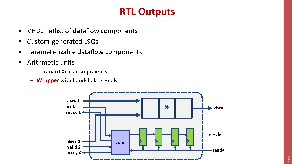
RTL Outputs • • VHDL netlist of dataflow components Custom-generated LSQs Parameterizable dataflow components Arithmetic units – Library of Xilinx components – Wrapper with handshake signals * data 1 valid 1 ready 1 data valid data 2 valid 2 ready 2 Join ready 6 7
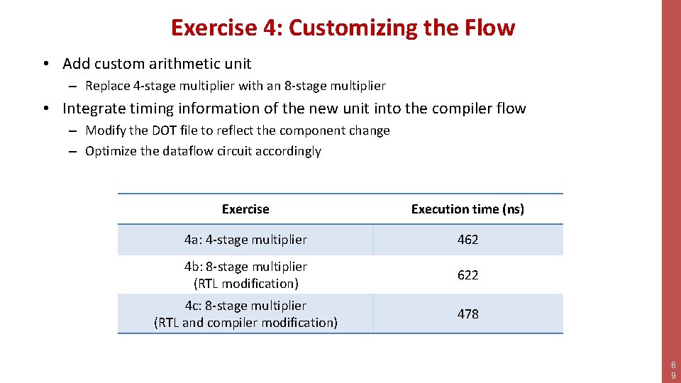
Exercise 4: Customizing the Flow • Add custom arithmetic unit – Replace 4 -stage multiplier with an 8 -stage multiplier • Integrate timing information of the new unit into the compiler flow – Modify the DOT file to reflect the component change – Optimize the dataflow circuit accordingly 6 8
Exercise 4: Customizing the Flow • Add custom arithmetic unit – Replace 4 -stage multiplier with an 8 -stage multiplier • Integrate timing information of the new unit into the compiler flow – Modify the DOT file to reflect the component change – Optimize the dataflow circuit accordingly Exercise Execution time (ns) 4 a: 4 -stage multiplier 462 4 b: 8 -stage multiplier (RTL modification) 622 4 c: 8 -stage multiplier (RTL and compiler modification) 478 6 9
Dynamatic: From C/C++ to Dynamically Scheduled Circuits • High-level synthesis will play a key role in accelerator “programming” – Current HLS techniques force worst-case assumptions (e. g. , memory and control dependencies) and preclude key performance optimizations (e. g. , speculation) • It is time to look at new paradigms for HLS – Dataflow circuits for irregular and control-dominated applications Dynamatic now available on dynamatic. epfl. ch 7 0