
Fundamentals of Electric Circuits Chapter 1 Copyright The
- Slides: 30
Fundamentals of Electric Circuits Chapter 1 Copyright © The Mc. Graw-Hill Companies, Inc. Permission required for reproduction or display.
Introduction • This chapter introduces the concept of voltage and current. • The concept of a circuit will be introduced. • Sources will be introduced. • These can provide either a specified voltage or current. • Dependent and independent sources will be discussed. • Also a strategy for solving problems will be introduced. 2
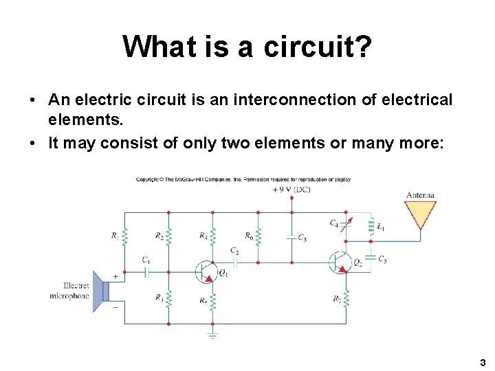
What is a circuit? • An electric circuit is an interconnection of electrical elements. • It may consist of only two elements or many more: 3
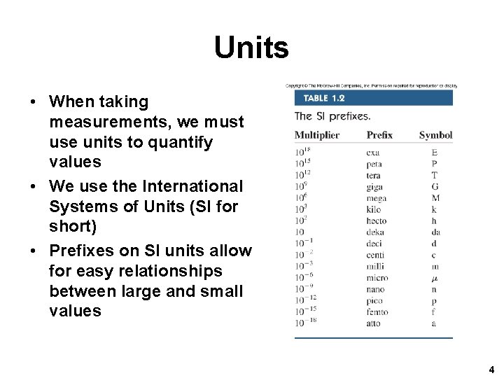
Units • When taking measurements, we must use units to quantify values • We use the International Systems of Units (SI for short) • Prefixes on SI units allow for easy relationships between large and small values 4
Charge • Charge is a basic SI unit, measured in Coulombs (C) • Counts the number of electrons (or positive charges) present. • Charge of single electron is 1. 602*10 -19 C • One Coulomb is quite large, 6. 24*1018 electrons. • From WIKEPEDIA, (Electric) charge is the physical property of matter that causes it to experience a force when placed in an electromagnetic field. There are two types of electric charges; positive and negative 5
Charge II • In the lab, one typically sees (p. C, n. C, or μC) • Charge is always multiple of electron charge • Charge cannot be created or destroyed, only transferred. 6
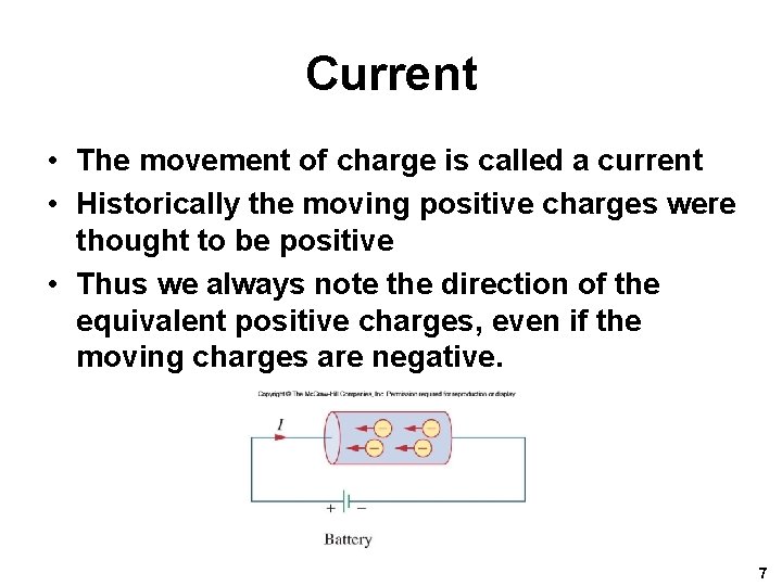
Current • The movement of charge is called a current • Historically the moving positive charges were thought to be positive • Thus we always note the direction of the equivalent positive charges, even if the moving charges are negative. 7
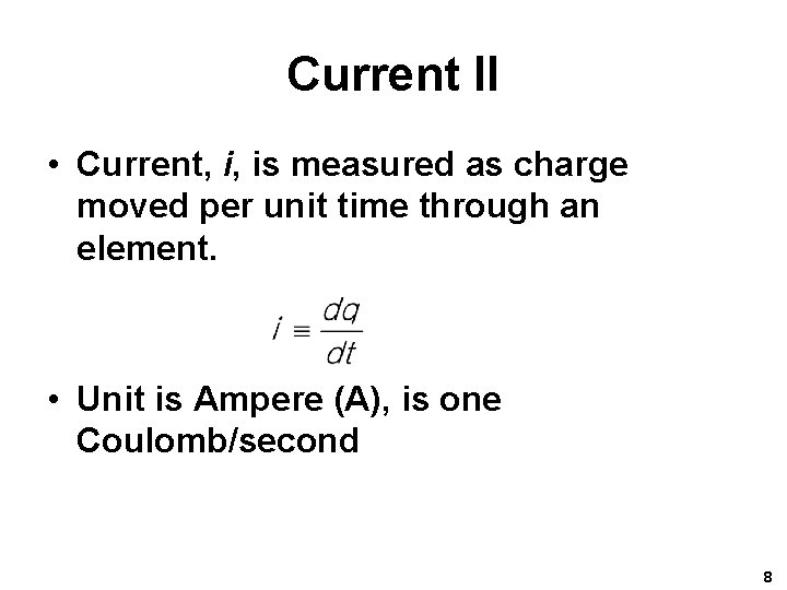
Current II • Current, i, is measured as charge moved per unit time through an element. • Unit is Ampere (A), is one Coulomb/second 8
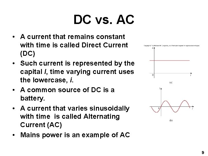
DC vs. AC • A current that remains constant with time is called Direct Current (DC) • Such current is represented by the capital I, time varying current uses the lowercase, i. • A common source of DC is a battery. • A current that varies sinusoidally with time is called Alternating Current (AC) • Mains power is an example of AC 9
Direction of current • The sign of the current indicates the direction in which the charge is moving with reference to the direction of interest we define. • We need not use the direction that the charge moves in as our reference, and often have no choice in the matter. 10
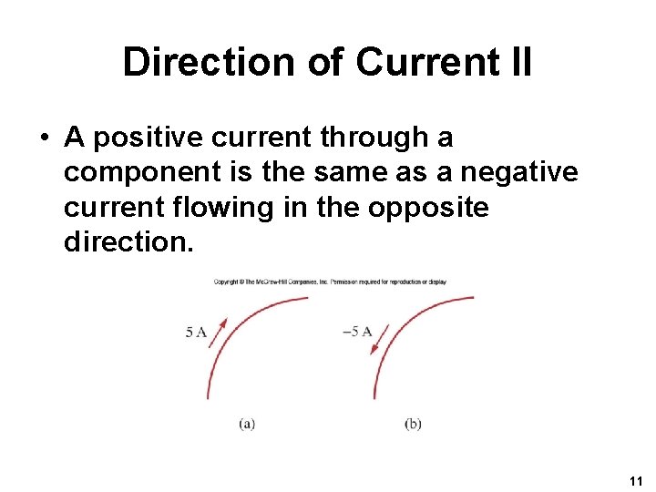
Direction of Current II • A positive current through a component is the same as a negative current flowing in the opposite direction. 11
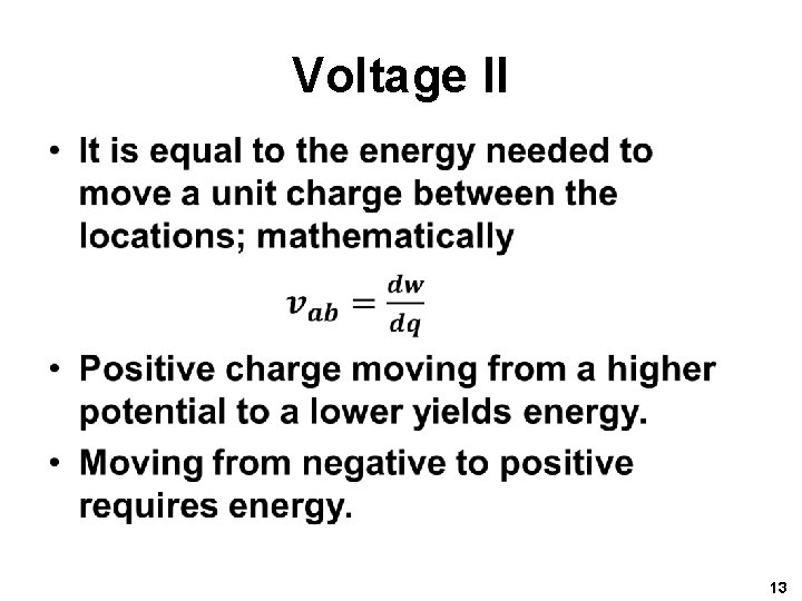
Voltage • Electrons move when there is a difference in charge between two locations. • This difference is expressed at the potential difference, or voltage, measured in volts(V). • It is always expressed with reference to two locations 12
Voltage II • 13
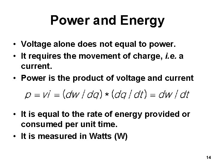
Power and Energy • Voltage alone does not equal to power. • It requires the movement of charge, i. e. a current. • Power is the product of voltage and current • It is equal to the rate of energy provided or consumed per unit time. • It is measured in Watts (W) 14
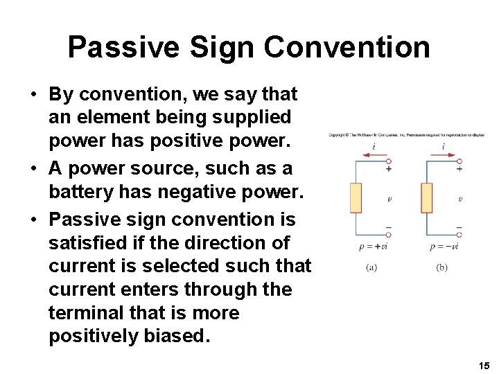
Passive Sign Convention • By convention, we say that an element being supplied power has positive power. • A power source, such as a battery has negative power. • Passive sign convention is satisfied if the direction of current is selected such that current enters through the terminal that is more positively biased. 15
Conservation of Energy • In a circuit, energy cannot be created or destroyed. • Thus power also must be conserved • The sum of all power supplied must be absorbed by the other elements. • Energy can be described as watts x time. • Power companies usually measure energy in watt-hours 16
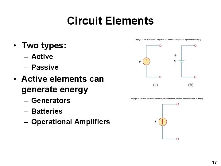
Circuit Elements • Two types: – Active – Passive • Active elements can generate energy – Generators – Batteries – Operational Amplifiers 17
Circuit Elements II • Passives absorb energy – Resistors – Capacitors – Inductors • But it should be noted that only the resistor dissipates energy ideally. • The inductor and capacitor do not. 18
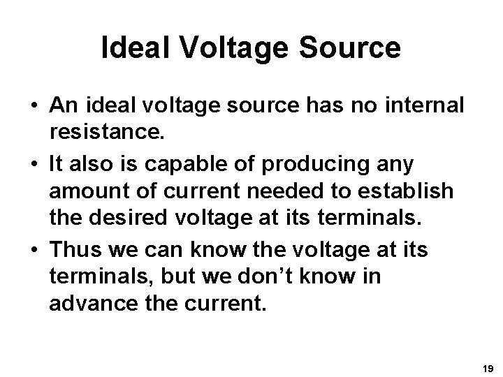
Ideal Voltage Source • An ideal voltage source has no internal resistance. • It also is capable of producing any amount of current needed to establish the desired voltage at its terminals. • Thus we can know the voltage at its terminals, but we don’t know in advance the current. 19
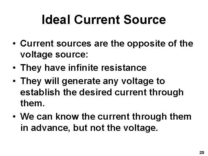
Ideal Current Source • Current sources are the opposite of the voltage source: • They have infinite resistance • They will generate any voltage to establish the desired current through them. • We can know the current through them in advance, but not the voltage. 20
Ideal sources • Both the voltage and current source ideally can supply infinite power. • They are also capable of absorbing power from the circuit. • It is important to remember that these sources do have limits in reality: • Voltage sources have an upper current limit. • Current sources have an upper voltage limit. 21
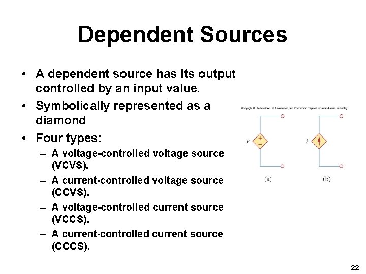
Dependent Sources • A dependent source has its output controlled by an input value. • Symbolically represented as a diamond • Four types: – A voltage-controlled voltage source (VCVS). – A current-controlled voltage source (CCVS). – A voltage-controlled current source (VCCS). – A current-controlled current source (CCCS). 22
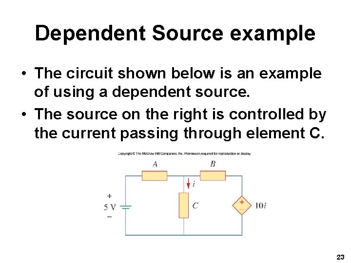
Dependent Source example • The circuit shown below is an example of using a dependent source. • The source on the right is controlled by the current passing through element C. 23
Circuit Applications of Dependent Sources • Dependent sources are good models for some common circuit elements: – Transistors: In certain modes of operation, transistors take either a voltage or current input to one terminal and cause a current that is somehow proportional to the input to appear at two other terminals. – Operational Amplifiers: Not covered yet, but the basic concept is they take an input voltage and generate an output voltage that is proportional to that. 24
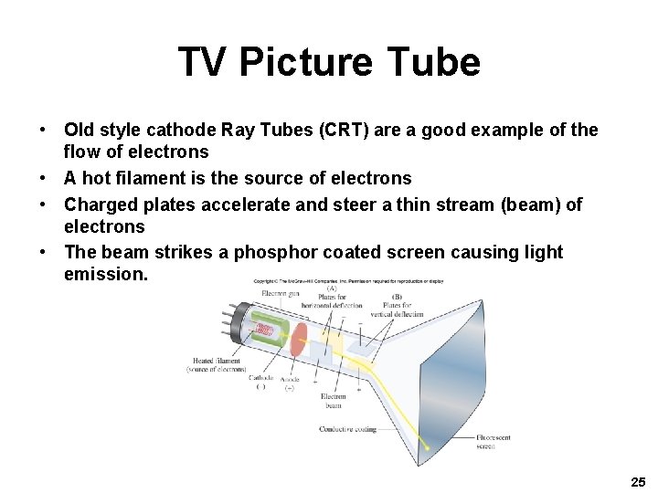
TV Picture Tube • Old style cathode Ray Tubes (CRT) are a good example of the flow of electrons • A hot filament is the source of electrons • Charged plates accelerate and steer a thin stream (beam) of electrons • The beam strikes a phosphor coated screen causing light emission. 25
Problem Solving I • Successfully solving an engineering problem requires a process. • Shown here is an effective method for determining the solution any problem. 1. Carefully define the problem. 2. Present everything you know about the problem. 3. Establish a set of alternative solutions and determine the one that promises the greatest likelihood of success. 26
Problem Solving II 4. Attempt a problem solution. 5. Evaluate the solution and check for accuracy. 6. Has the problem been solved satisfactorily? If so, present the solution; if not, then return to step 3 and continue through the process again. 27
Problem Solving III • Carefully define the problem – This is the most important step – What needs to be solved? – What questions need to be addressed before solving? Find the sources to answer them. • Present everything you know about the problem – What do you know? – What don’t you? 28
Problem Solving IV • Establish a set of alternative solutions and determine the one that promises the greatest likelihood of success. – Most problems have more than one way to be solved – But not all solutions are as simple – Are the required tools available? 29
Problem Solving V • Attempt to solve the problem – Documenting this process is very important • Evaluate the solution and check for accuracy – Does it makes sense? – Is it consistent with any assumptions made? • Is the solution satisfactory? If not, try an alternate solution. 30