PNEUMATIC CIRCUITS 1 Working of SINGLE acting cylinder


- Slides: 17

PNEUMATIC CIRCUITS 1

Working of SINGLE acting cylinder SINGLE ACTING CYLINDER, SPRING RETURNED A 2 1 P R FRL UNIT 3/2 DC VALVE MUFFLER(AIR EXHAUST) AIR RECEIVER COMPRESSOR 2

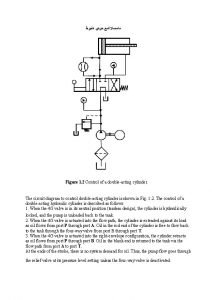
Working of DOUBLE acting cylinder A B 2 4/2 DC VALVE FRL UNIT AIR RECEIVER 1 P DOUBLE ACTING CYLINDER R COMPRESSOR 3

PILOT CONTROL SINGLE ACTING CYLINDER IMPULSE CIRCUIT A B SINGLE ACTING CYLINDER, SPRING RETURNED PILOT SIGNAL (COMPRESSED AIR) MAIN 3/2 DC VALVE 2 1 R PUSH BUTTON OPERATED 3/2 DCV (START VALVE) P 1 MUFFLER 2 R COMPRESSOR AIR RECEIVER FRL UNIT P 4

PILOT CONTROL DOUBLE ACTING CYLINDER IMPULSE CIRCUIT A B SINGLE ACTING CYLINDER, SPRING RETURNED PILOT SIGNAL (COMPRESSED AIR) MAIN 4/2 DC VALVE 2 1 P PUSH BUTTON OPERATED 3/2 DCV (START VALVE) R 1 MUFFLER 2 R COMPRESSOR AIR RECEIVER FRL UNIT P 55

Working of PILOT CONTROLLED UNIDIRECTIONAL AIR MOTOR A UNIDIRECTIONAL AIR MOTOR BUTTON OPERATED 3/2 DC VALVE PILOT OPERATED 3/2 DC VALVE 2 1 2 P P R MUFFLER(AIR EXHAUST) R IMPULSE CIRCUIT FRL UNIT MOISTURE SEPARATOR AIR RECEIVER COMPRESSOR 6

Working of PILOT CONTROLLED BIDIRECTIONAL AIR MOTOR A BUDIRECTION AL AIR MOTOR BUTTON OPERATED 3/2 DC VALVE PILOT OPERATED 3/2 DC VALVE 2 1 2 P P R MUFFLER(AIR EXHAUST) R IMPULSE CIRCUIT FRL UNIT MOISTURE SEPARATOR AIR RECEIVER COMPRESSOR 7

SPEED CONTROL OF SINGLE acting cylinder SINGLE ACTING CYLINDER, SPRING RETURNED A FLOW CONTROL VALVE WITH CHECK VALVE 2 1 P R FRL UNIT 3/2 DC VALVE MUFFLER(AIR EXHAUST) AIR RECEIVER COMPRESSOR 8

SPEED CONTROL OF DOUBLE acting cylinder A B DOUBLE ACTING CYLINDER FLOW CONTROL VALVE WITH CHECK VALVE (2) 2 4/2 DC VALVE FRL UNIT AIR RECEIVER 1 P R COMPRESSOR 9

SPEED CONTROL OF BIDIRECTIONAL AIR MOTOR BUDIRECTION AL AIR MOTOR 1 4/2 DC VALVE P FRL UNIT A 2 R MUFFLER(AIR EXHAUST) MOISTURE SEPARATOR AIR RECEIVER COMPRESSOR 10

SEQUENCING OF DOUBLE ACTING CYLINDER WITH UNIDIRECTIONAL AIR MOTOR DOUBLE ACTING CYLINDER A B LIMIT SWITCH 4/2 DC VALVE START P 3/2 DC SOLENOID VALVE R MUFFLER FRL UNIT COMPRESSOR 11

TIME DELAY CIRCUIT DOUBLE ACTING CYLINDER A 3/2 ROLLER OPERATED DC VALVE B TIME DELAY VALVE Y Z P R 4/2 DC VALVE MUFFLER FRL UNIT COMPRESSOR 12

13

Time delay circuits A time delay in a peumatic circuit provides a delay between the operation of a valve and the movement of a piston. Time delays are achieved by connecting a unidirectional-flow control valve and a reservoir in series. A pneumatic circuit with a time delay is shown in the diagram and explained below. 14

The time-delayed pneumatic circuit works like this: When the push-button on the three-port valve on the left is pressed, the air flow is restricted by the unidirectional-flow control valve and slowly enters the reservoir. The pressure builds in the reservoir slowly, causing the time delay. Only when the pressure in the reservoir is high enough will it operate the five-point valve, triggering the release of air and causing the piston to outstroke. When the push button is pressed on the second threeport valve (on the right), the five-point valve will switch, triggering the release of air and causing the piston to instroke. 15

The length of the time delay can be altered using an adjustable unidirectional-flow control valve. Do not confuse time delay with speed control. Time delay prevents the piston operating for a particular time period. Speed control reduces the speed of the piston's instroke or outstroke. 16

THANKS !!! DOUGHTS, QUERIES WELCOMED. 17
 Fluidsim pneumatics examples
 Function of single acting cylinder in pneumatic system
 Memory valve is also known as
 Rodless cylinder working principle
 Number 4 represents
 Hydraulic heater symbol
 Gravity return single acting cylinder
 Simbol kapasitas
 Diagram step pneumatik
 What is a parallel circuit in physics
 Method acting vs natural acting
 Pneumatic cylinder basics
 Gambar actuator silinder double action
 Regulator pneumatic symbol
 Hydraulic cylinder cushions
 Transpose prescription examples
 Single loop circuits
 Single acting baking powder
