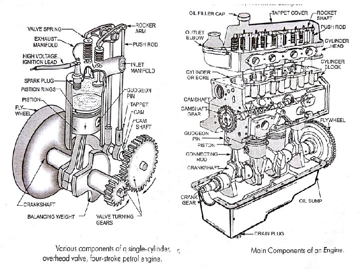
Engine construction CYLINDER BLOCK the cylinder block cylinder

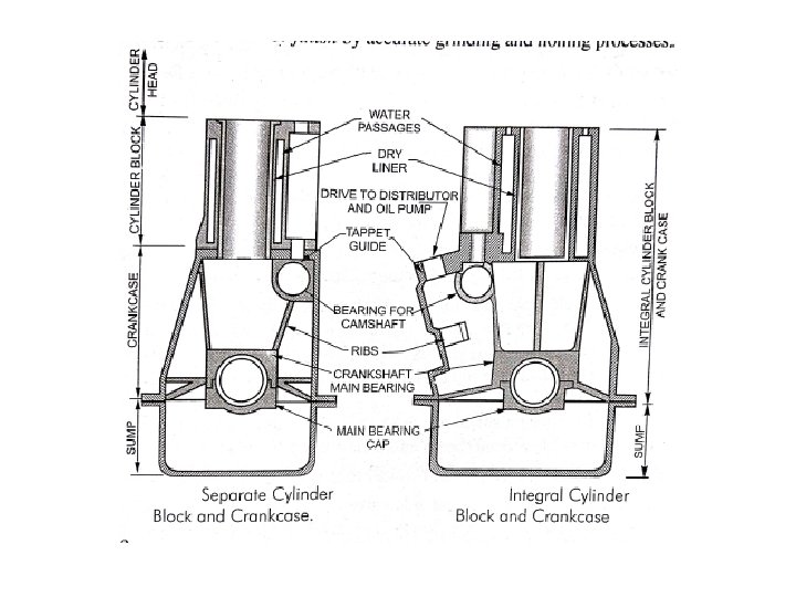
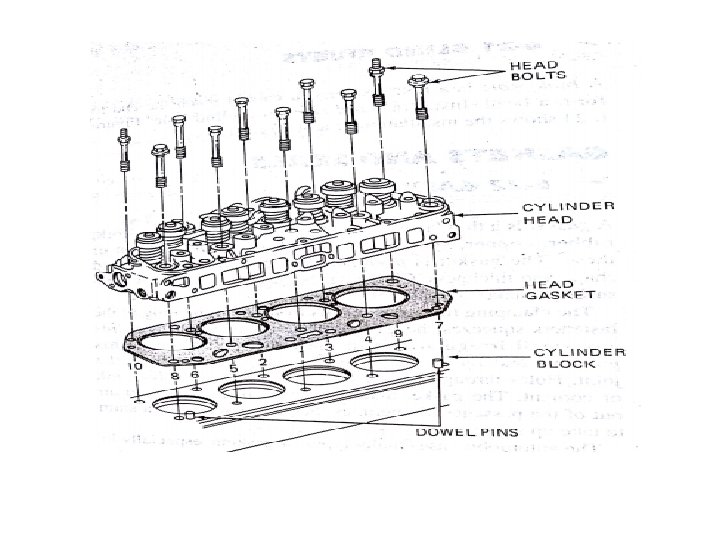
Engine construction CYLINDER BLOCK: • the cylinder block , cylinder head and crank case – these parts form the foundation and main stationary body of the automobile engine. • They serve as support and enclosure for moving parts. • In modern engine, cylinder block and crankcase form a single casting, which gives a rigid structure. • Ribs are cast in the cylinder crank case to give it give extra strength and support the main and in some cases the camshaft bearings. The cylinder block consists of three parts 1) The cylinders in which the piston slides up and down. 2) The ports or opening for the valves. 3) The passages for the flow of cooling water. • The cylinder block is usually made from gray cast iron, sometimes with addition of nickel and chromium.

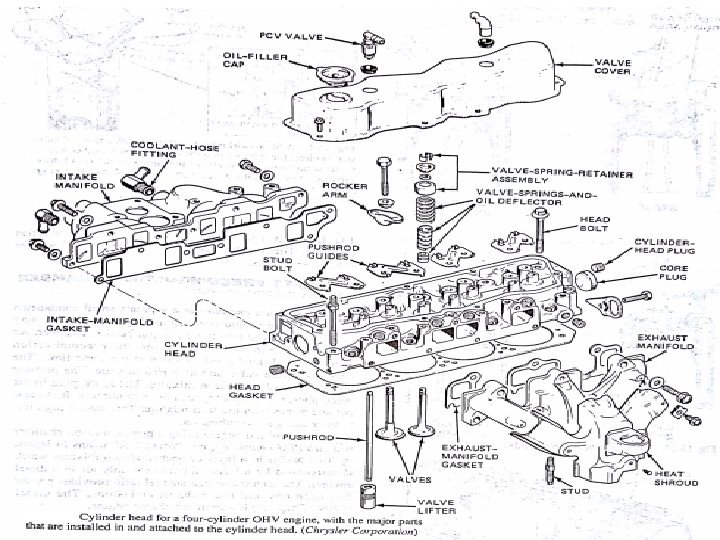
CYLINDER HEAD: • The top of the cylinder is covered by a separate Cast piece is known as the cylinder Head. • It consist of combustion chamber, spark plug valves ate mounted. • It incorporates passages for the flow of cooling water. • The cylinder head is usually made of gray iron or aluminium alloy. Aluminium has the advantages of lightness in weight and heat conductivity. • A flat piece of gasket is placed between the cylinder head and cylinder block. • Depending upon the valve layout, the cylinder head may carry the camshaft, rockers and valves, water passages are provided adjacent to the valve and plug seating.

CRANKCASE: • The crankcase is attached to the bottom face of the cylinder block. • It is act as the base of the engine. • It support the crankshaft and camshaft in suitable bearings and provides the arms for supporting the engine on frame. • The oil pan and lower part of the cylinder block together are called the crankcase. • The cylinder block and upper half of the crankcase usually are cast a single integral unit. This casting is usually made of ferrous alloy to provide a stronger. • Aluminium alloy is potentially attractive material for crankcases, because of light weight , good thermal conductivity and good cooling effect.

Cylinder Head Gaskets: • A gasket is placed between the cylinder head and cylinder block to retain the compression in the cylinder, to prevent the leakage and to ensure metallic tight fit joint. • The gasket should be able to withstand not only high pressure but also extreme temperature. • The gaskets are coated with a special varnish which melts and seal all the small intersticks of the block and head when the engine warms. • Suitable holes are made in the gasket to pass the studs and for cylinder bore. • Following important gaskets are used in Automobile engines: 1) Copper- asbestos gasket, 2) Steel -asbestos gasket, 3) steel –asbestos-Copper gasket. 4) Single steel ridged gasket, 5) stainless steel gasket.

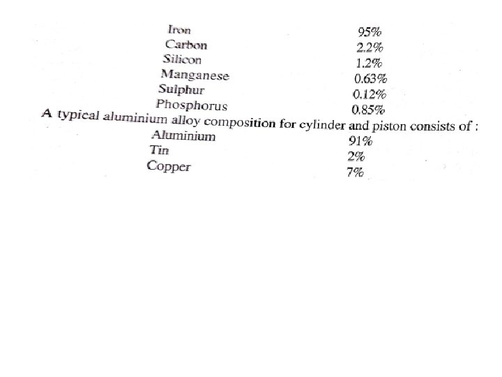
CYLINDER LINER : • The cylinder liner is separate barrels or a sleeve are fitted in the cylinder block, in which the piston of an engine reciprocates. • The liners are removable and can be replaced when worn or damaged. • The cylinder liner are made superior materials like nickel-chromium iron(carbon 3. 5%, Manganese 0. 6%, Phosphorous 1. 5%, sulphur 0. 05%, silicon 2%, nickel 2% and chromium 0. 7%) • To increase the wear resistance, the liners are hardened by heating to 855 0 C-8650 C for 30 to 40 minutes then quenched in oil. • The life of a cylinder between its re- bores depends on two main factors: 1) Abrasion and 2)corrosion • Abrasion depends on the atmospheric condition and the efficiency of the filter and oil filter. Dusty atmospheric air is more harmful as it increases abrasion in the cylinder. • Corrosion of the cylinder is caused due to the corrosive products of combustion. Which are formed after burning of fuel with air.
 Dry")
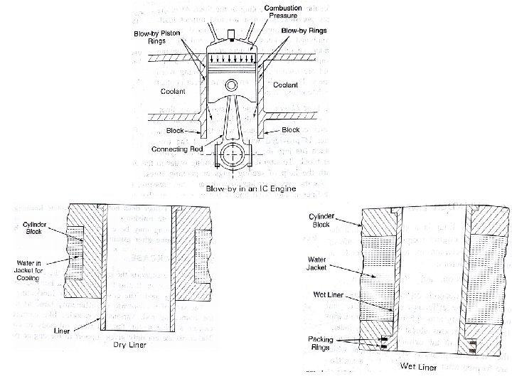
Types of Liners: the cylinder liners or sleeves are of two types 1) Dry liners, 2)wet liners 1) Dry liners: Dry liners are made in the shape of a barrel having a flange at the top. • The flange keeps the liner in position and fits accurately in the cylinder block. • The perfect contact of liner with the cylinder block is necessary for effective cooling. • Also , the gas pressure, piston thrust and impact loading during combustion resisted by the combined thickness of the liner and cylinder. • The dry liners are thinner having thickness varying from 1. 5 mm to 3 mm and these liners are not in direct contact with cooling water.
Wet liners: wet liner is so called because the cooling water comes in contact")
2)Wet liners: wet liner is so called because the cooling water comes in contact with the liners. • This liner is provided with flange at top which fits the groove made by cylinder block and to stop leakage of cooling water in the crankcase the lower end of the wet liner is seals with the help of the sealing rings or packing rings. • The wet liners thickness range from 3 mm to 6 mm. • The outer side of the liners coated with aluminium so that is protected from rust. • The wet liners is better cooled than the dry liner and easily removable when it is worn -out or damaged.

PISTON: • Piston is considered to be on of the most important parts in a reciprocating engine in which it helps to convert the chemical energy obtained by the combustion of fuel into useful mechanical power. • Piston is a essentially a cylindrical plug that moves up and down in the cylinder and it appears to be simple part, but it is quit complex from the design point. • It is equipped with piston rings to good seal between the cylinder wall and piston. • It must operate in the cylinder with minimum friction and should be able to withstand high explosive force(4 to 6 N/mm 2)developed in the cylinder and also the very high temperature ranging from 2000 o. C to 2800 o. C during operation. • The piston are being cast from aluminium alloy (aluminium with copper, silicon, nickel. . etc. , ) Nomenclature of a piston: 1) Piston head: the top of the piston is called a piston head. It form a floor of the combustion chamber. 2) Ring grooves: the ring grooves are cut on the circumference of the upper portion of the piston. The piston rings are fitted in the ring grooves.
Skirt: the part below the ring grooves are called a skirt. The purpose of")
3)Skirt: the part below the ring grooves are called a skirt. The purpose of the skirt is to make the motion of the piston smooth, and also to improve piston cooling performance by increasing the area of contact between the piston and cylinder wall. 4) Land: the portion of the piston that separates the grooves is called land. 5) Piston Bosses: are the reinforced section of the piston designed to hold piston pin(wrist pin)

The piston must possess the following qualities: • Rigidly to withstand at high pressure. • Light in weight. • Good thermal conductivity. • Silence in operation. • Material having low expansion.

PISTON RINGS: • Piston rings are fitted into the groves of the piston to maintain good seal between the piston and cylinder wall. Piston rings are usually made of fine- grained alloy cast iron. • All the rings have a joint (they are spilt) so that they can be expanded and easily assembled in their grooves. The functions of the piston rings: 1) To provide a pressure seal to prevent blow-by of burnt gases. 2) To form the main path for conduction of heat from the piston crown to the cylinder walls. 3) To control the flow of oil to the skirt.
 Compression rings 2) oil control rings. 1) Compression rings")
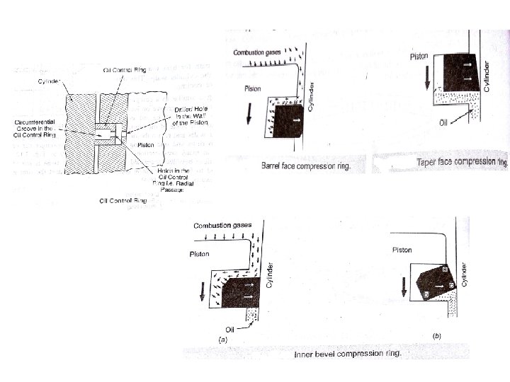
Types of piston rings: 1) Compression rings 2) oil control rings. 1) Compression rings : the compression rings are fitted on the top of the piston. It serve two purposes viz. i) To seal the combustion chamber ii) To provide a path for heat transfer from the piston to the cylinder walls. This provides effective cooling. 2) Oil rings: An oil rings are similar to a compression rings but has a circumferential grooves on its outer circumferences. The function oil rings is to strip some of the lubricating oil from the cylinder walls and return the oil to the crankcase through radial passages in the oil ring.

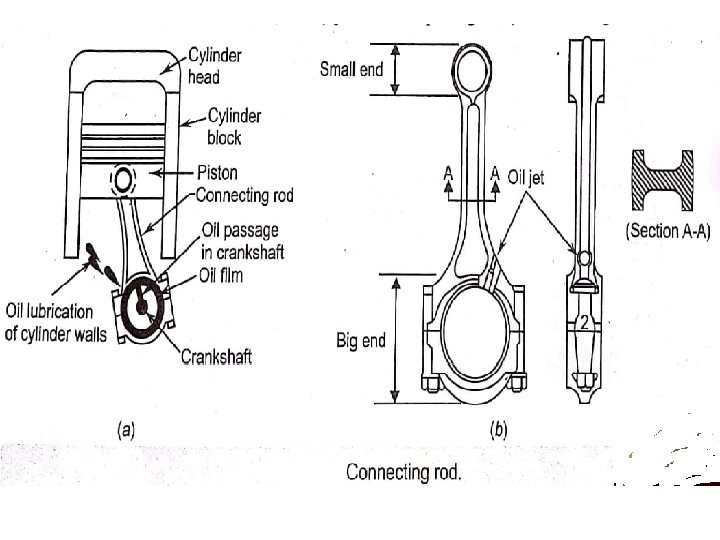
CONNECTING ROD: • The connecting rod connects the piston and crankshafts. • Small end of the connecting rod is connected to piston with wrist pin and big end to the crank with crank pin. • The function of the connecting rod is to convert linear motion of the piston into rotary motion of the crankshaft. • The connecting rod usually has I-beam cross-section. • The connecting rods are die-forged from special steel such as nickel-chrome steel and chrome molybdenum steel and are mechanically strengthened. • The connecting rod should have the following qualities i) It should be very strong and stiff. ii) It should be light in weight to minimise vibration.

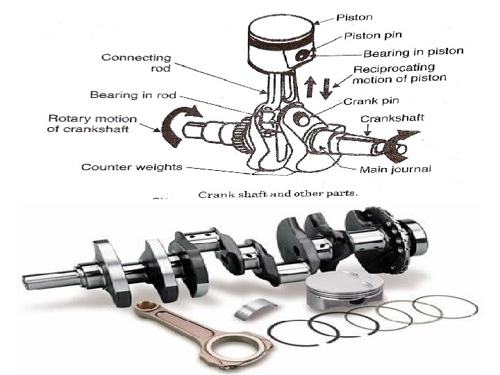
CRANK SHAFT: • The crankshaft is an important part of the engine which converts the reciprocating motion of piston into rotary motion. • The crankshaft is subjected to torsional and bending stresses and is supported on the crank case structure on large bearings. • These crank shaft bearings are known as main bearings. • The main bearings and the crankpin bearings are made large so that the load is distributed evenly. • The load on the main bearings due to centrifugal force is reduced of made zero by providing suitable counter weights(dead- weights). • It is usually a steel forging, but some makers use special type of cast-iron such as spheroidal graphitic or nickel alloy castings which are cheaper and have good service.
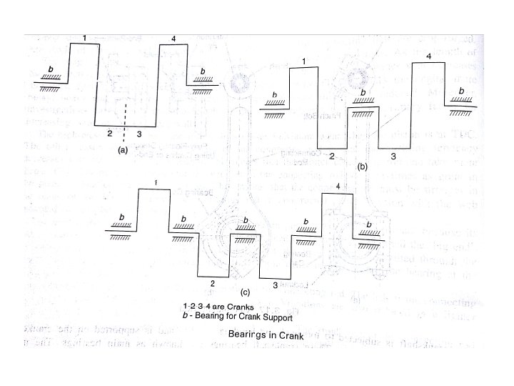

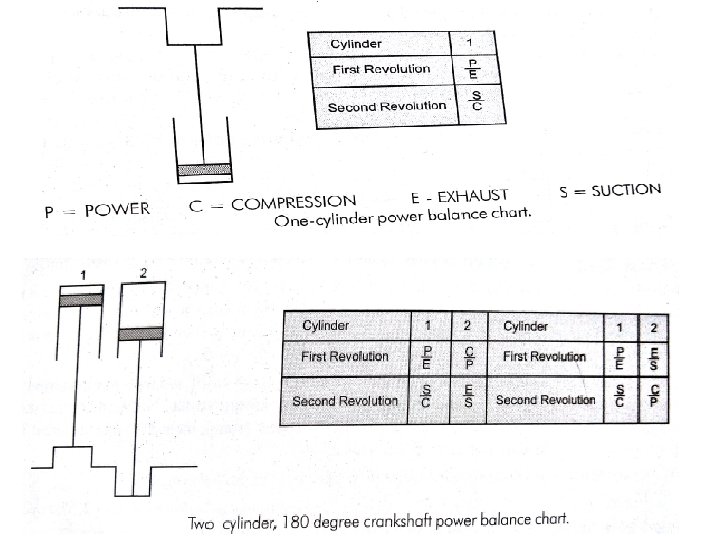
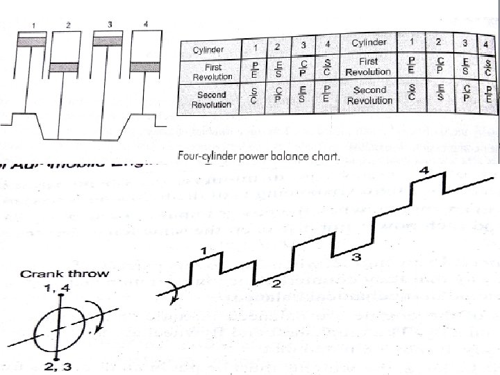
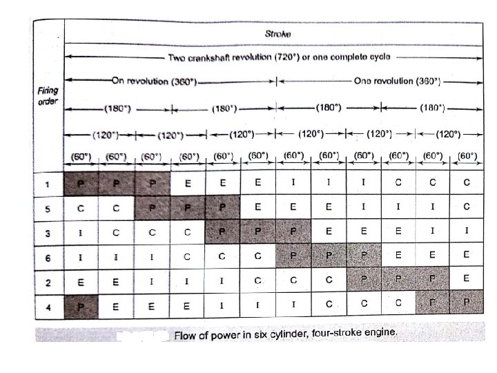
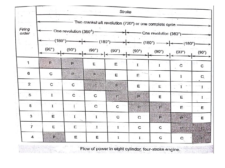
FIRING ORDER: • To achieve better balancing of the dynamic forces and their couples the multicylinder engines have even number of cylinders that is 4 -cylinder, 6 -cylinder, 8 cylinder engines. • The crank arrangement of a four cylinder engine has been shown, crank 1 and 2 are mirror images of crank 3 and 4 with respect to the plane AB. The firing orders are arranged at an internal of (360 x 2)/4 = 180 o • For 6 -cylinder (360 x 2)/6 = 120 o • For 8 -cylinder (360 x 2)/8 = 90 o The following advantages are for proper firing order: 1) It reduces engine vibration. 2) It secures an even flow of power. 3) It maintains engine balance
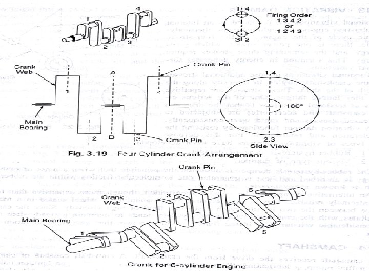

• Firing order is 1 -4 -2 -6 -3 -5( for left hand crank case), Firing order is 1 -5 -3 -6 -2 -4( for right hand crank case)

• The firing order in the eight cylinder in line engine is 1 -6 -2 -5 -8 -3 -7 -4, the other firing order may be 1 -7 -3 -8 -4 -6 -2 -5 and 1 -5 -2 -6 -4 -8 -3 -7

POWER OVER LAP:

CAMSHAFT: • A cam shaft is used to open and close valves in the appropriate timings. It made up of different cams formed on a common shaft. • The camshaft contains the same number of cams as same number of valve in the engine. • The cams are elliptical in shape, the major axis length is referred as the cam lobe height. The difference between the major axis and minor axis length is referred to as the cam lift. • The camshaft are usually forged from special steel including nickel, chrome and molybdenum or cast from special cast iron. • The cams are given surface hardening treatment to improve the wear resistance.

Cylinder-block-mounted camshaft Cylinder-head-mounted camshaft
 Overhead")
VALVE MECHANISM Two basic types of valve mechanisms generally used in Vehicles 1) Overhead valve mechanism(OHV). 2) Overhead camshaft mechanism (OHC).
 Overhead valve mechanism(OHV): • • • • The crankshaft drives the camshaft through")
1) Overhead valve mechanism(OHV): • • • • The crankshaft drives the camshaft through timing gears. There a series of lobes on the camshaft which control the valve movement. The lifter are above the lobes and there are one lobe for each lifter. The camshaft lifts the valve lifter(tappet) which in turn operates the pushrod. The motion is transferred to the top of head through the pushrod. The pushrod further transfers this motion tot the rocker arm through the adjusting screw. In the center of the rocker arm, there is a shaft known as rocker shaft. The rocker arm is pivoted about this shaft. When one end the rocker arm is lifted by the pushrod, the other end goes down and pushes the valve down to open it in the cylinder head. The valve moves in the valve guide secured to the head. The opening of the valve puts the valve spring in compression. When the cam rotates further, the cam lobe loses contact with the tappet and compression in the spring lift the valve and pushes the tappet up. The same action is repeated by the contact of the cam lobe with the tappet.
 Overhead camshaft mechanism (OHC): • The principle on which this mechanism works is")
2) Overhead camshaft mechanism (OHC): • The principle on which this mechanism works is the as used in the overhead valve mechanism. • This system does not have any pushrod as the camshaft is mounted on top of the head. • The rocker arms are placed over or under the cam. • The rocker arms then reach away from the cam to the valves. • Many in-line OHC engines use one cam shaft. • These are called as SOHC(single overhead camshaft). • In the past few year, to increase engine output, some engines have two camshaft, giving a DOHC (double overhead camshaft) layout. • One camshaft operates the intake valves and the other camshaft operates the exhaust valves.

VALVES: • The function of the intake and exhaust valves is to open and close the openings between the intake and exhaust ports and the combustion chambers. • The fresh gases enter into the combustion chamber through the inlet valves and used gases go of the combustion chamber through the exhaust valves. • The valves are usually made of austenitic stainless steel which is a corrosion and heat resisting materials. • The exhaust valves is usually made of silchrome steel which is an alloy of silicon and chromium. • The Inlet valve is made with nickel chromium alloy steel. • The valves used in modern passengers car engines are termed as poppet or mushroom valves. • The intake valves are larger in dimensions then exhaust valves.
 Head: it is the broad face of the")
Various parts of poppet valve: 1) Head: it is the broad face of the valve and carries the valve face. • During working of the engine, it is the hottest part of the valve. • The valve having hollow and concave head is known as trumpet valve and is generally used for inlet valve. • The convex head valve is known as mushroom valve and used as exhaust valve. 2) Face : It is a circular and angular seating surface machined on the valve head. • This is generally machined at an angle of either 300 or 450 to sit on the similarly inclined surface of the valve seat and makes a tight joint. 3) stem: It is a working surface of the valve and this portion of the valve moves up and down in the valve guide. • The heat of the valve head is conducted to the stem and it is dissipated to the cylinder head through the valve guide. 4) Tip: It is the flat end of the stem over which the rocker arm acts to open the valve. • This tip is generally deposited with coating of a hard metal to resist wear.

SODIUM COOLED VALVES: • The sodium cooled valve, as shown in fig. has a hallow stem, which is partly filled with metallic sodium. • Since the melting point of sodium is 970 C, so at operating temperature, it is liquid. • When the valve moves up and down, the sodium is thrown upwards into the hotter part of the valve. • Sodium absorbs heat and gives it up to the cooler the valve head down into the stem again. • This circulation cools the valve head and the valve, and hence it runs cooler resulting in longer life.

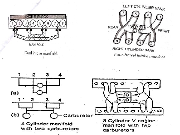
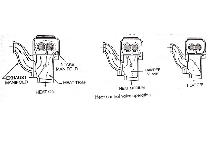
INTAKE MANIFOLDS: • The intake manifold serves the important purpose of guiding the charge or air into the individual cylinders. • It is an articulate passage to make the intake of each cylinder uniform by mass and of the correct quality. • The intake manifold should ensure a smooth flow along the shortest possible distance before the charge entry into the engine cylinders. • This prevents condensation of fuel and a more homogeneous mixture of air and fuel. • Petrol needs assistance to vaporize and this achieved by heating the intake manifold by diverting the exhaust gases or circulating the cooling water over intake manifold or providing hot spots or plugs in intake manifold at points where the fuel may impinge and condense. • The inner surface of the intake manifold and the runners should be smooth and without sharp bends and projections at the joints. • The manifold is attached at the top of the engine block close to the inlet ports and valves. The intake manifold is mounted 1)on the side of the cylinder block in L- head engine. 2) on the side of the cylinder head in I- head engine. 3) in between the cylinder banks on V-8 engine. • The intake manifold is a cast iron or aluminium alloy and having smooth finish with in tube for carrying the air-fuel mixture from the carburettor to the engine intake port. Functions of intake manifolds: 1)It supply equal amount of charge to each cylinder. 2) It also maintain the air-fuel ration of charge. 3)There should not be any restriction to charge movement. 4)It should not allow the charge to condense in it.

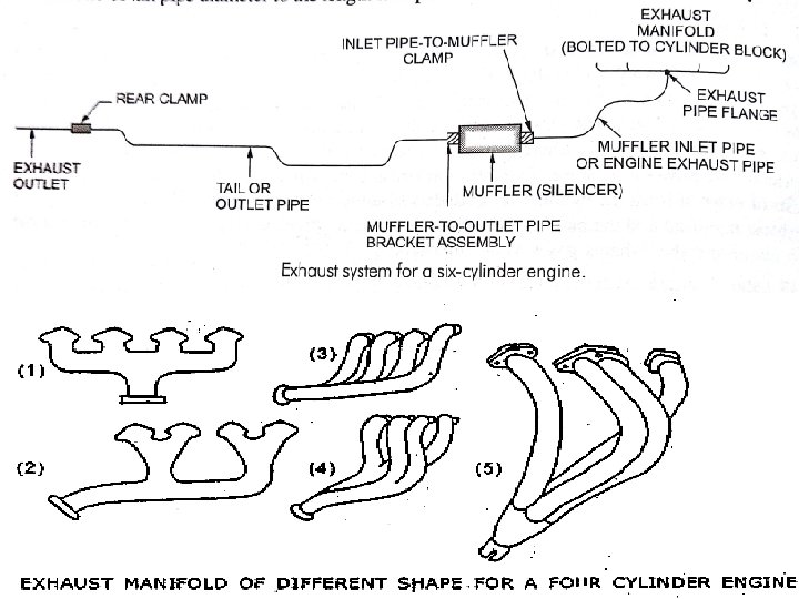
EXHAUST MANIFOLDS: • The exhaust manifold is a tube for carrying the exhaust gases away from the engine cylinders. • It collects exhaust gases from the exhaust port of the various cylinders and conducts them to a central exhaust passage. • The exhaust manifold is usually made of cast iron and it is bolted to the side of the cylinder block. • The exhaust manifolds are designed to avoid overlapping of exhaust strokes, as far as possible, thus keeping the back pressure to a minimum. • This is often done by dividing the exhaust manifold into two or more branches, so that two cylinders will not exhaust into the same branch at the time. • Large radius bends are provided in the design to eliminate any restriction in the flow.

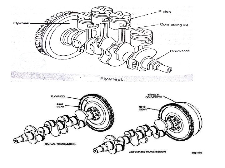
FLYWHEEL: • A flywheel is very heavy disc of cast iron attached to the rear end of the crankshaft. • It is used in order to keep crankshaft in regular motion as the flow of power from the engine cylinders is not smooth. • The inertia of flywheel tends to keep the crankshaft turning at the constant speed. • The following are the important functions of the flywheel: 1) It stores the energy received in power stroke and keeps the crank shaft rotating in idle stoke. 2) It maintains the speed of crankshaft. 3) It transmits the engine power to the gearbox through a clutch plats. 4) For starting the engine, the starter ring is fitted on its periphery.
- Slides: 49