Chapter 6 Hydraulic Cylinders and Cylinder Cushioning Learning


 schematic drawing (b) graphic symbol It consists of a piston")
 schematic drawing (b) graphic symbol Such a cylinder can")


 - piston velocity (v)")


- Slides: 25
Chapter 6: Hydraulic Cylinders and Cylinder Cushioning
Learning Objectives 1. Describe the construction and design features of hydraulic cylinders. 2. Identify the various types of hydraulic cylinder mountings and mechanical linkages for transmitting power 3. Calculate the load-carrying capacity, speed, and power of hydraulic cylinders during the extending and retracting strokes 4. Determine the maximum pressure developed by cushions at the ends of a hydraulic cylinder. 5. Explain the operation and features of double rod cylinders and telescoping cylinders. 6. Describe the purpose, construction, and operation of hydraulic shock relief absorbers. 7. Analyze hydraulic cylinder piston rod forces resulting from driving external loads via various mechanical linkages.
a. single-acting cylinder (a) schematic drawing (b) graphic symbol It consists of a piston inside a cylindrical housing called a barrel. Attached to one end of the piston is a rod, which extends outside one end of the cylinder (rod end). At the other end (blank end) is a port for the entrance and exit of oil. A single-acting cylinder can exert a force in only the extending direction as fluid from the pump enters the blank end of the cylinder. Single- acting cylinders do not retract hydraulically. Retraction is accomplished by using gravity or by the inclusion of a compression spring in the rod end
a. Double -acting cylinder (a) schematic drawing (b) graphic symbol Such a cylinder can be extended and retracted hydraulically. Thus, an output force can be applied in two directions (extension and retraction). This particular cylinder has a working pressure rating of 2000 psi for its smallest bore size of 1⅛ in and 800 psi for its largest bore size of 8 in.
Nomenclature of a double-acting cylinder - the barrel is made of seamless steel tubing, honed to a fine finish on the inside. - The piston is made of ductile iron - contains U-cup packing to seal against leakage between the piston and barrel. - The ports are located in the end caps, which are secured to the barrel by tie rods. - The tapered cushion plungers provide smooth deceleration at both ends of the stroke.
Cylinder Mountings And Mechanical Linkages Various types of cylinder mountings are in existence, as illustrated in the figure. This permits versatility in the anchoring of cylinders. The rod ends are usually threaded so that they can be attached directly to the load, a clevis, a yoke, or some other mating device. Through the use of various mechanical linkages, the applications of hydraulic cylinders are limited only by the ingenuity of the fluid power designer. As illustrated in the figure , these linkages can transform a linear motion into either an oscillating or rotary motion. In addition, linkages can also be employed to increase or decrease the effective leverage and stroke of a cylinder.
Typical mechanical linkages that can be combined with hydraulic cylinders
Misalignment Problems Much effort has been made by manufacturers of hydraulic cylinders to reduce or eliminate the side loading of cylinders created as a result of misalignment. It is almost impossible to achieve perfect alignment even though the alignment of a hydraulic cylinder has a direct bearing on its life. A universal alignment mounting accessory designed to reduce misalignment problems is illustrated in Figure 6 -6. By using one of these accessory components and a mating clevis at each end of the cylinder (see Figure 6 -6), the following benefits are obtained: 1. Freer range of mounting positions 2. Reduced cylinder binding and side loading 3. Allowance for universal swivel 4. Reduced bearing and tube wear
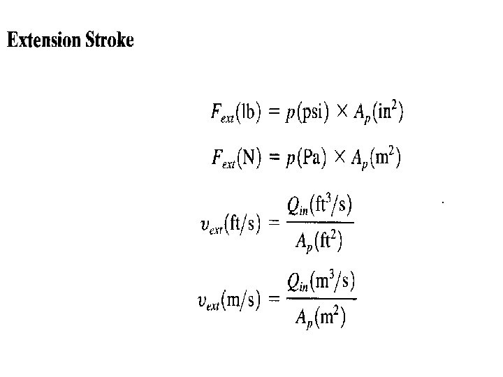
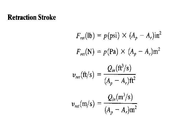
CYLINDER FORCE, VELOCITY. AND POWER - The output force (F) - piston velocity (v) of double-acting cylinders are not the same for extension and retraction strokes
q During the extension stroke, fluid enters the blank end of the cylinder through the entire circular area of the piston (Ar). q During the retraction stroke, fluid enters the rod end through the smaller annular area between the rod and cylinder bore (A, , — Ar), where A, , equals the piston area and Ar equals the rod area. q This difference in flow-path cross-sectional area accounts for the difference in piston velocities. Since A, , is greater than (A, , — Ar), the retraction velocity is greater than the extension velocity for the same input flow rate. q During the extension stroke, fluid pressure bears on the entire circular area of the piston. q During the retraction stroke, fluid pressure bears only on the smaller annular area between the piston rod and cylinder bore. This difference in area accounts for the difference in output forces. Since A, , is greater than (A, , — Ar), the extension force is greater than the retraction force for the same operating pressure.
CYLINDER FORCE, VELOCITY. AND POWER
Example: a pump supplies oil at 20 gpm ro a 2 -in-diameter double acting
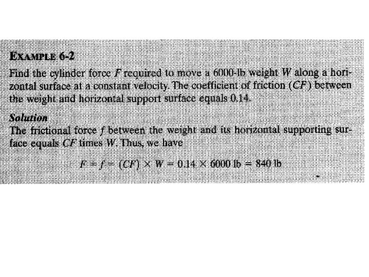
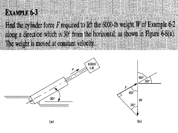
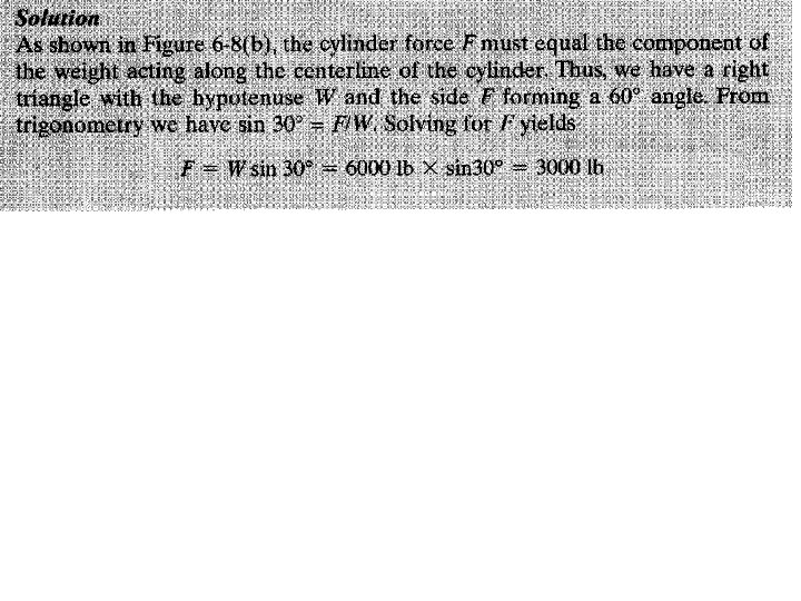
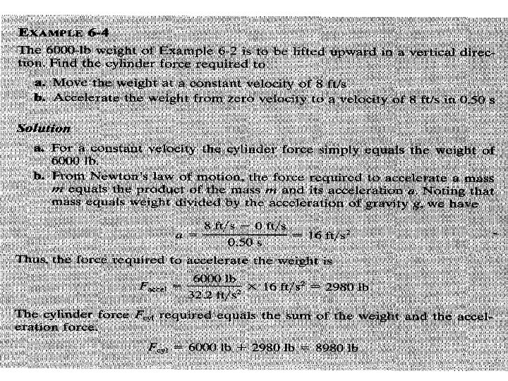
CYLINDER LOADS DUE TO MOVING OF WEIGHTS
• In the case of a vertical cylinder, the load simply equals the weight of the object because gravity acts in a downward, vertical direction. • Sometimes a cylinder is used to slide an object along a horizontal surface. In this case, the cylinder load is theoretically zero. This is because there is no component of the object’s weight acting along the axis of the cylinder (a horizontal direction). However, as the object slides across the horizontal surface, the cylinder must overcome the frictional force created between the object and the horizontal surface. This frictional force, which equals the load acting on the cylinder, opposes the direction of motion of the moving object. If the cylinder is mounted in neither a vertical nor horizontal direction, the cylinder load equals the component of the object’s weight acting along the axis of the cylinder, plus a frictional force if the object is sliding along an inclined surface. Thus for an inclined cylinder, the load the cylinder must overcome is less than the weight of the object to be moved if the object is not sliding on an inclined surface.
HYDRAULIC CYLINDER CUSHIONS -Cylinder cushions are used to slow the piston down near the ends of the stroke. -a check valve is used to allow free flow to the piston during direction reversal. -The maximum pressure developed by cushions at the ends of a cylinder must be considered since excessive pressure buildup would rupture the cylinder.
Control of a double acting cylinder
Control of a double acting cylinder a. Control of a double acting cylinder 4/2 way valve -The 4/2 way valve or the 5/2 way valve can be used to control the double acting cylinder. In both cases the air is initially supplied from 1(P) to 2(B) and the 4(A) port is exhausted. -The cylinder is initially held under pressure in the retracted position. -When the manual valve is operated the 4(A) port is active and the 2(B) port is exhausted. --The cylinder is extended, and remains extended until the valve is released. In the 4/2 way valve a single exhaust port 3(R) is used.
b. Control of a double acting cylinder 5/2 way valve -In the case of the 5/2 way valve, the exhaust air is separately exhausted to atmosphere from one of the two ports 3(S) or 5(R). - It is more common for the 5/2 way valve to be used for the control of the double acting cylinder.