CONNECTIONS IN STEEL STRUCTURES IS 800 2007 CRITERIA


")


 Fillet (Mostly used, Weaker than groove")


 connections Moment (rigid) connections")


 An Angle is")


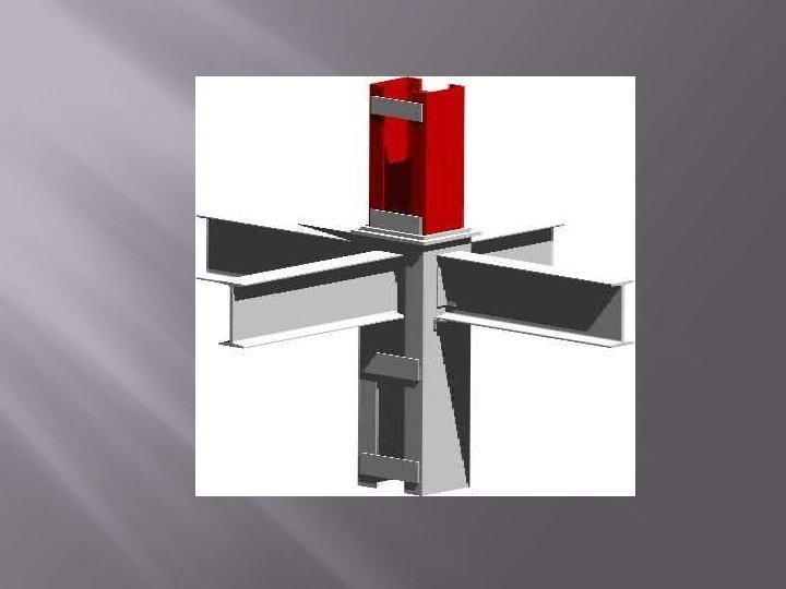
 Beam to Column Connections")


- Slides: 64
CONNECTIONS IN STEEL STRUCTURES IS 800 -2007 CRITERIA
Connections are structural elements used for joining different members of a structural steel frame work. Steel Structure is an assemblage of different member such as “BEAMS, COLUMNS” which are connected to one other, usually at member ends fastners, so that it shows a single composite unit.
BASED ON FORCES TO BE TRANSFERED TRUSS CONNECTIONS FULLY RESTRAINED CONNECTONS PARTIALLY RESTRAINED CONNECTIONS SPLICES BARCKETS BASED ON PLACEMENT OF PARTS TO BE JOINED LAP JOINT BUTT JOINT
Bolts Weld
Connecting Plates Connecting Angles
On the Basis of Connecting Medium. According to the type of internal forces. According to the type of structural Elements According to the type of members joining
Riveted Connections Bolted Connections
Welded Connections Bolted-Welded Connections
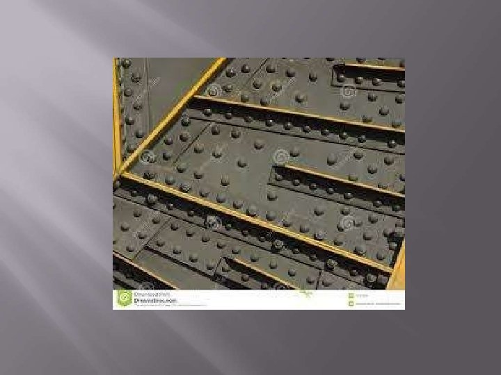
Used for very long time. Made up of: Round Ductile steel bar called shank. A head at one end The length of the rivet should sufficient to form the second head. Design - very similar to bearing type of bolted connection.
Heating of the rivet Inserting it to an oversize hole pressure to the head. Squeezing the plain End by Pneumatic driver Round head. On Cooling Reduces in Length–Clamping Force
The introduction of high strength structural bolts. The labour costs associated with large riveting crews The cost involved in careful inspection and removal of poorly installed rivets. The high level of noise associated with driving rivets.
Fastened Together primarily by Bolts may be loaded in: Tension Shear Both Tension & Shear Threads of bolts under shear force: Excluded Included - Increased strength Decreased stregth.
Bearing type bolts High strength friction grip bolts (HSFG)
1. The most common type is bearing bolts in clearance holes, often referred to as Black Bolts Ordinary, unfinished, rough, or common bolts. Least Expensive Primarily - Light structures under static load such as small trusses, purlins etc
2. Turned Bolts Similar to unfinished bolts. Shanks - Hexagonal Rods Primarily - Light structures under static load such as small trusses, purlins etc Expensive – Limited use – Structures with no Slippage Connections
3. Ribbed Bolts • Round head similar to Rivets. • Raised ribs parallel to the shank. • Actual Diameter - slightly Larger than the hole • Tightly fit into the hole. • Popular - Economical in Material & Installation
Uses when bearing type bolts slips under shear High strength bolts (8 G or 10 K grade) Pre-tensioned against the plates to be bolted together so that contact pressure developed between the plates being joined Prevents relative slip when extra shear is applied Higher Shear Resistance.
Advantages 1. The bolting operation is very silent 2. Bolting is a cold process hence there is no risk of fire 3. Bolting operation is more quicker than riveting. 4. Less man power is required in making the connections. Disadvantages 1. If subjected to vibratory loads, results in reduction in strength get loosened. 2. Unfinished bolts have lesser strength because of non uniform diameter
whose components are joined together primarily by welds. Welding Notations were developed by American Welding Society (AWS).
• Groove ( More reliable than others) Fillet (Mostly used, Weaker than groove and others) Plug (expensive – poor transmission of tensile forces) Slot (expensive - poor transmission of tensile forces) Plug and Slot welds – stitch different parts of members together.
Horizontal Vertical Overhead Flat
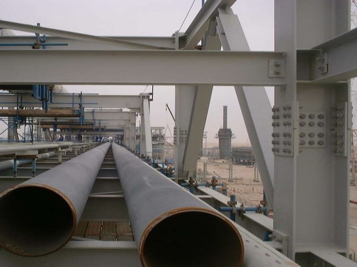
Economical – Cost of materials and labors. Efficiency is 100% as compared to rivets (75 - 90%) Fabrication of Complex Structures – Easy – like Circular Steel pipes. Provides Rigid Joints – Modern Practice is of Rigid Joints.
No provision for expansion or contraction therefore greater chances of cracking. Uneven heating and cooling - member may distort may result in additional stresses. Inspection is difficult and more costlier than rivets
Most connections are Shop Welded and Field Bolted types. More Cost Effective Better Strength & Ductility characteristics –Fully w elded.
Shear (semi rigid, simple) connections Moment (rigid) connections
Allows the beam end to rotate without a significant restraint. Transfers shear out of beam Most Common Types: Double clip Shear End Plate Fin Plate
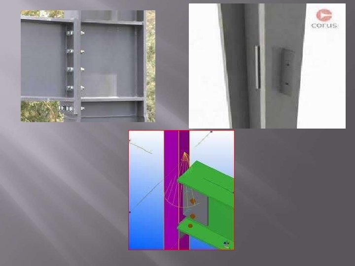
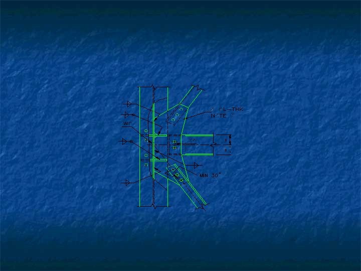
Designed to resist both Moment and Shear. Often referred - rigid or fully restrained connections • Provide full continuity between the connected members • Designed to carry the full factored moments. Principal Reason - buildings has to resist the effect of lateral forces such as wind and earthquake.
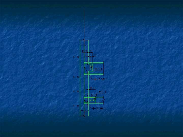
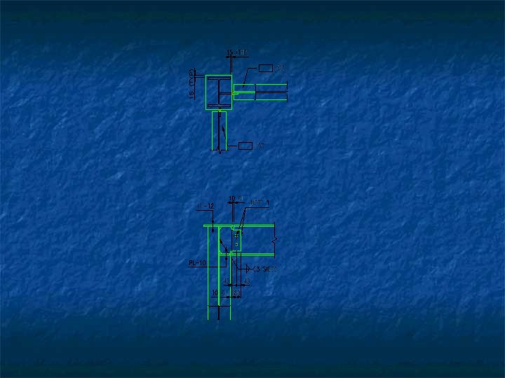
Bolted splice Moment Connection Field Bolted Moment Connection
Single plate angle Connections Double web angle connections Top and seated angle connections Seated beam connections
Two Step Process A plate is welded to secondary section (beam) An Angle is welded to Primary Section (column or Beam) single shear plate welded to secondary beam and bolted to Primary beam or column.
Two angles welded or shop bolted to the web of a secondary beam. After erection the angles are bolted or site welded to the primary member (beam or column).
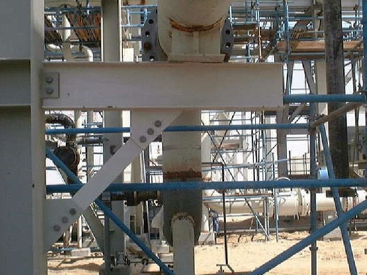
Generally used in case of moment connections. Two angles are provided at top and bottom of the beam to resist moment. Generally used for lesser moments where heavy loads are not acting
Generally used in case of shear connections. A seating angle - at bottom of secondary beam - shop welded to the primary member. Seating angle resists vertical shear coming from the beam.
Beam to beam connections Column to column connections (column splices) Beam to Column Connections Column Base Plate Connections
Two Types Primary Beam to Secondary Beam Connection Beam Splice
Connects column to column. Column splice comes under this category. Used to connect column sections of different sizes. Splices - designed for both moment and shear unless intended to utilize the splices as internal hinges.
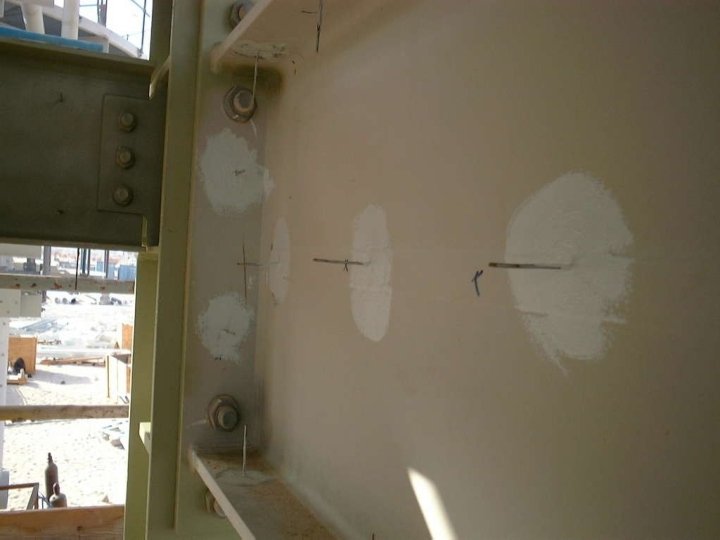
Connects Beam to column. Very Common A wide range of different types are used Fin Plates End Plates Web or Flange Cleats Hunched Connections
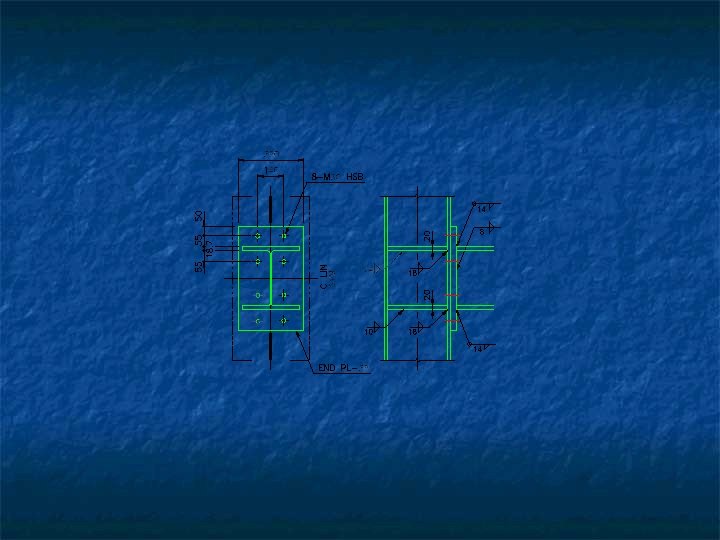
Beams are normally attached using two or more bolts through the web. End plate connections single plate welded to the end of the beams Bolted to the column flange or web - two or bolts pair. Fin plate connections Single Plate welded to the Column. Beams are normally attached using two or more bolts through the web.
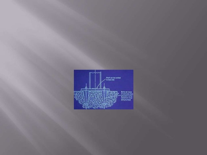
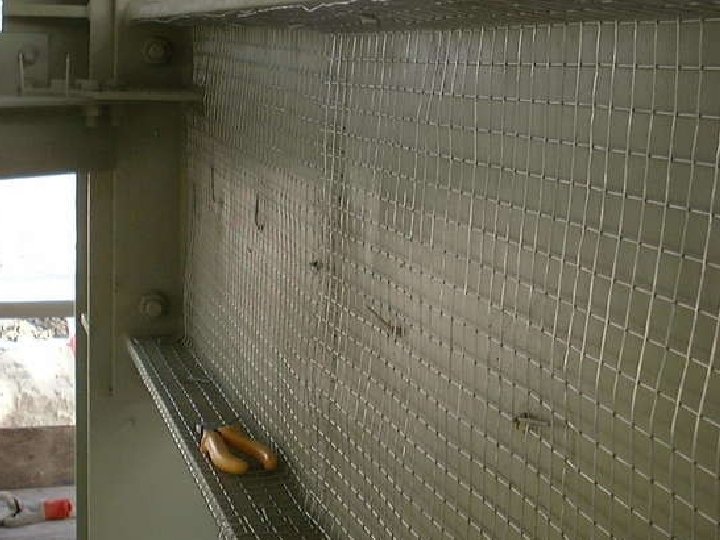
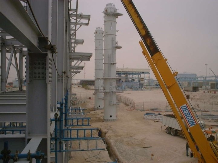
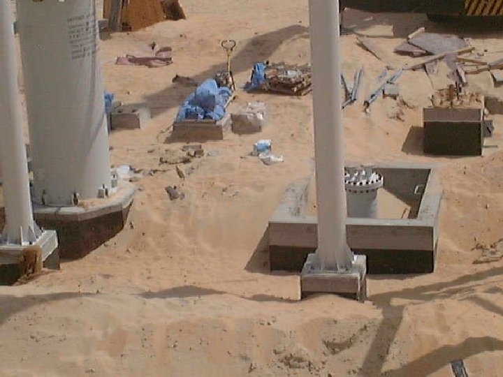
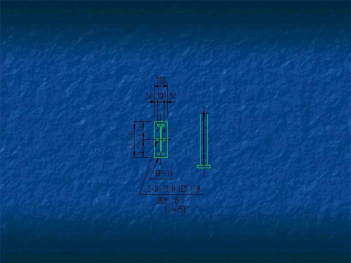
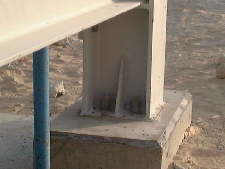
Steel plates placed at the bottom of Columns. Function - to transmit column loads to the concrete pedestal. The design of a column base plate: determining the size of the plate. determining the thickness of the plate
A layer of grout should be placed between the base plate and its support for the purpose of leveling. Anchor bolts should be provided to stabilize the column during erection or to prevent uplift.
TRUSS CONNECTIONS In truss connections only the axial forces are to be transferred. These are simplest in all types of connections which may either be welded or bolted.
FULLY RESTRAINED/MOMENT CONNECTIONS These connections are particularly used when continuity between the members of the building frame is required to provide more flexural resistance and reduce lateral deflection due to wind loads. In this type of connection both the webs and flanges are connected. In this connection greater than 90% moment can be transferred with full transfer of shear and other forces
PARTIALLY RESTRAINED CONNECTIONS These connections have rigidity less than 90%. The original angles between the connected members may change up to a certain limit after the application of loads. These connections can transfer some percentage of moment along with full shear force. SIMPLESHEAR CONNECTIONS These connections have less than 20% rigidity. These are considered flexible and beams become simply supported. In this case only the web is connected with the other member because most of shear stresses are concentrated in the web.
SEMI-RIGID CONNECTIONS These types of connections provide rigidity in between fully restrained and simple connections and approximately 20% to 90% moment compared with ideal rigid joint may be transferred. These type of connections are mostly used in practice because their performance is exceptionally well under cyclic loads and earthquakes
SPLICES These are used to extend the length of a particular member. These connections may be bolted or welded.
BRACKETS These are the connections which used to transfer moment besides other type of forces. The term bracket is generally used for an extra plate projecting out of column and acting like a seat for the beam.
COLUMN BASE CONNECTIONS These connections can either be pined or fixed depending upon the type of forces to be transferred.