1 C 8 Advanced design of steel structures






- Slides: 24
1 C 8 Advanced design of steel structures prepared by Josef Machacek
List of lessons 1) Lateral-torsional instability of beams. 2) Buckling of plates. 3) Thin-walled steel members. 4) Torsion of members. 5) Fatigue of steel structures. 6) Composite steel and concrete structures. 7) Tall buildings. 8) Industrial halls. 9) Large-span structures. 10) Masts, towers, chimneys. 11) Tanks and pipelines. 12) Technological structures. 13) Reserve. 2
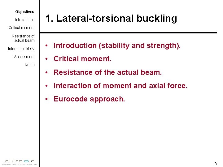
Objectives Introduction 1. Lateral-torsional buckling Critical moment Resistance of actual beam Interaction M+N Assessment • Introduction (stability and strength). • Critical moment. Notes • Resistance of the actual beam. • Interaction of moment and axial force. • Eurocode approach. 3
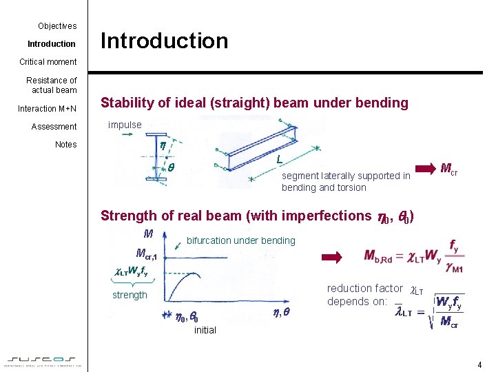
Objectives Introduction Critical moment Resistance of actual beam Interaction M+N Assessment Stability of ideal (straight) beam under bending impulse Notes L segment laterally supported in bending and torsion Mcr Strength of real beam (with imperfections 0, 0) M bifurcation under bending Mcr, 1 strength 0 , 0 , reduction factor LT depends on: initial 4
Objectives Introduction Critical moment Resistance of actual beam Stability of ideal beam under bending (determination of Mcr) Interaction M+N Assessment "Basic beam" - with y-y axis of symmetry z (simply supported in bending and torsion, loaded only by M) Notes y y Two equations of equilibrium (for lateral and torsional buckling) may be unified into one equation: z The first non-trivial solution gives M = Mcr: where 5
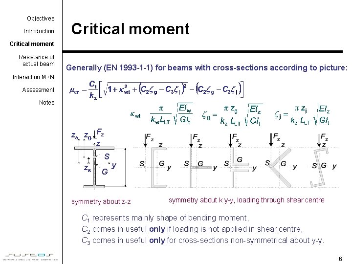
Objectives Introduction Critical moment Resistance of actual beam Generally (EN 1993 -1 -1) for beams with cross-sections according to picture: Interaction M+N Assessment Notes za zg Fz z S zs G y symmetry about z-z symmetry about k y-y, loading through shear centre C 1 represents mainly shape of bending moment, C 2 comes in useful only if loading is not applied in shear centre, C 3 comes in useful only for cross-sections non-symmetrical about y-y. 6
Objectives Introduction Critical moment Resistance of actual beam Interaction M+N Assessment Notes Procedure to determine Mcr: 1. Divide the beam into segments of lengths LLT according to lateral support: segment 3 segment 2 e. g. segment 1: (LLT, 1) segment 1 lateral support (bracing) in bending and torsion (lateral support "near" compression flange is sufficient) from table factor C 1 1: 2. Define shape of moment in the segment: 1 e. g. segment 2: ~2, 56 ~1, 77 a) usually linear distribution b) almost never ~1, 13 ~1, 35 (because loading here creates continuous support) 7
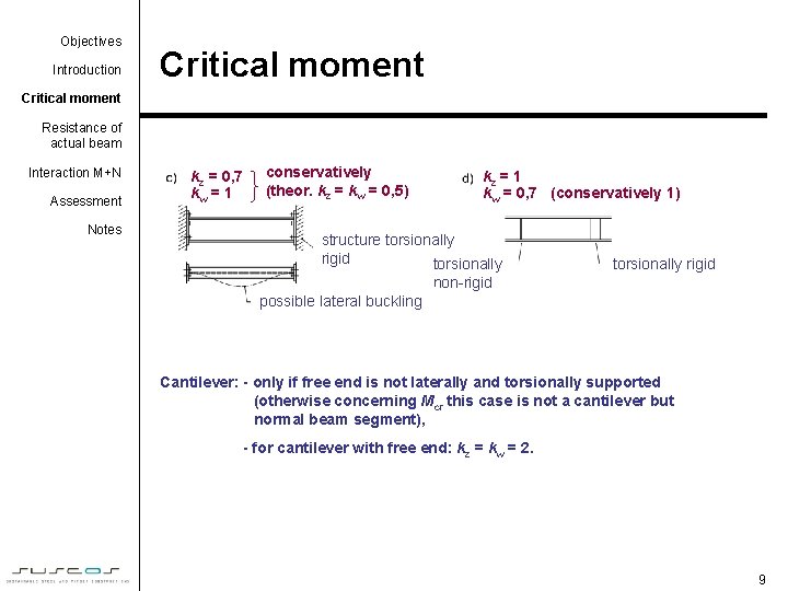
Objectives Introduction Critical moment Resistance of actual beam Interaction M+N Assessment Notes 3. Determine support of segment ends: (actually ratio of "effective length") kz = 1 (pins for lateral bending) kw = 1 (free warping of cross section) Other cases of k : kz = 1 kw = 1 angle of torsion is zero stiffener non-rigid in torsion possible lateral buckling kz = 1 kw = 0, 5 stiffener rigid in torsion (½ tube) possible lateral buckling
Objectives Introduction Critical moment Resistance of actual beam Interaction M+N Assessment Notes kz = 0, 7 conservatively konzervativní (theor. kz hodnoty = kw = 0, 5) kw = 1 kz = 1 kw = 0, 7 (conservatively 1) structure torsionally rigid non-rigid possible lateral buckling Cantilever: - only if free end is not laterally and torsionally supported (otherwise concerning Mcr this case is not a cantilever but normal beam segment), - for cantilever with free end: kz = kw = 2. 9
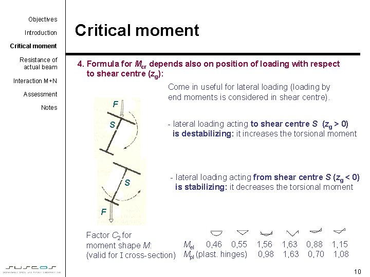
Objectives Introduction Critical moment Resistance of actual beam Interaction M+N 4. Formula for Mcr depends also on position of loading with respect to shear centre (zg): Come in useful for lateral loading (loading by end moments is considered in shear centre). Assessment F Notes - lateral loading acting to shear centre S (zg > 0) is destabilizing: it increases the torsional moment S S - lateral loading acting from shear centre S (zg < 0) is stabilizing: it decreases the torsional moment F Factor C 2 for Mel 0, 46 0, 55 moment shape M: (valid for I cross-section) Mpl (plast. hinges) 1, 56 1, 63 0, 88 1, 15 0, 98 1, 63 0, 70 1, 08 10
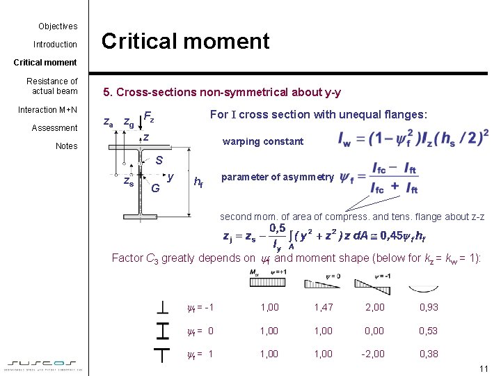
Objectives Introduction Critical moment Resistance of actual beam Interaction M+N Assessment Notes 5. Cross-sections non-symmetrical about y-y For I cross section with unequal flanges: za zg Fz z warping constant S zs G y hf parameter of asymmetry second mom. of area of compress. and tens. flange about z-z Factor C 3 greatly depends on f and moment shape (below for kz = kw = 1): f = -1 1, 00 1, 47 2, 00 0, 93 f = 0 1, 00 0, 53 f = 1 1, 00 -2, 00 0, 38 11
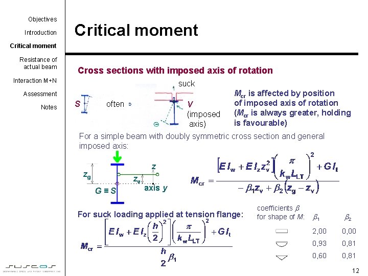
Objectives Introduction Critical moment Resistance of actual beam Cross sections with imposed axis of rotation Interaction M+N suck Mcr is affected by position of imposed axis of rotation (Mcr is always greater, holding is favourable) Assessment Notes S often V (imposed axis) For a simple beam with doubly symmetric cross section and general imposed axis: z zg zv G≡S axis y For suck loading applied at tension flange: coefficients for shape of M: 1 2 2, 00 0, 93 0, 81 0, 60 0, 81 12
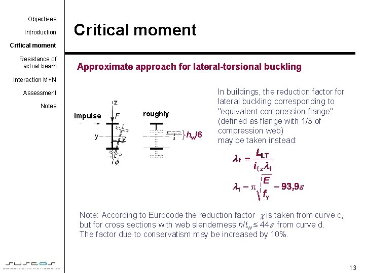
Objectives Introduction Critical moment Resistance of actual beam Approximate approach for lateral-torsional buckling Interaction M+N Assessment Notes impulse roughly hw/6 In buildings, the reduction factor for lateral buckling corresponding to "equivalent compression flange" (defined as flange with 1/3 of compression web) may be taken instead: Note: According to Eurocode the reduction factor is taken from curve c, but for cross sections with web slenderness h/tw ≤ 44 from curve d. The factor due to conservatism may be increased by 10%. 13
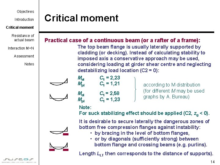
Objectives Introduction Critical moment Resistance of actual beam Interaction M+N Assessment Notes Practical case of a continuous beam (or a rafter of a frame): The top beam flange is usually laterally supported by cladding (or decking). Instead of calculating stability to imposed axis a conservative approach may be used, considering loading at girder shear centre and neglecting destabilizing load location (C 2 = 0): Mel Mpl C 1 = 2, 23 C 1 = 1, 21 Mel Mpl C 1 = 2, 58 C 1 = 1, 23 according to M distribution (for different M may be used graphs by A. Bureau) Note: For suck stabilizing effect should be applied (C 2, zg < 0). It is desirable to secure laterally the dangerous zones of bottom free compression flanges againstability: • by bracing in the level of bottom flanges, • or by diagonals (sufficiently strong) between bottom flange and crossing beams (e. g. purlins). Length LLT then corresponds to the distance of supports). 14
Objectives Introduction Critical moment Resistance of actual beam Interaction M+N Assessment Beams that do not lose lateral stability: 1. Hollow cross sections Reason: high It high Mcr Notes 2. Girders bent about their minor axis Reason: high It high Mcr 3. Short segment ( Reason: LT 1 )- all cross sections, e. g. 4. Full lateral restraint: "near" to the compression flange is sufficient ( approx. within h/4 ) compression flange loaded tension flange loaded zv ≥ 0, 47 zg zg zv ≤ 0, 47 zg or higher zv zv zg or anywhere higher 15
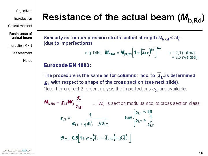
Objectives Introduction Resistance of the actual beam (Mb, Rd) Critical moment Resistance of actual beam Interaction M+N Assessment Notes Similarly as for compression struts: actual strength Mb, Rd < Mcr (due to imperfections) e. g. DIN: n = 2, 0 (rolled) = 2, 5 (welded) Eurocode EN 1993: The procedure is the same as for columns: acc. to is determined LT with respect to shape of the cross section (see next slide). Note: For a direct 2. order analysis the imperfections e 0 d are available. . Wy is section modulus acc. to cross section class 16
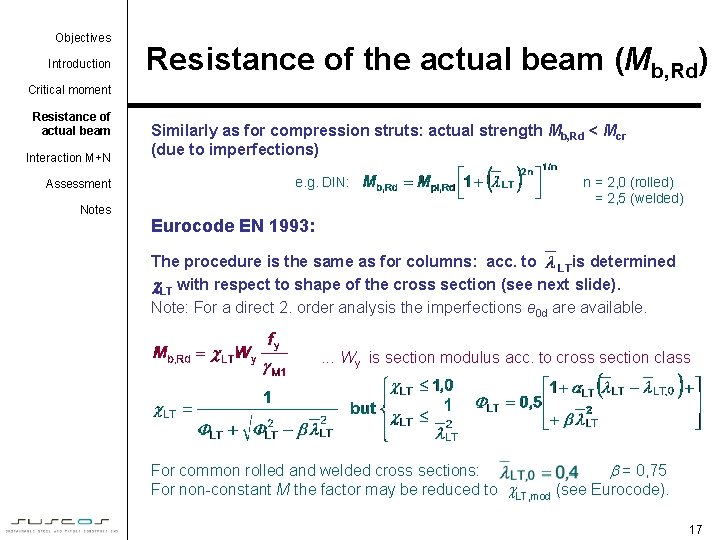
Objectives Introduction Resistance of the actual beam (Mb, Rd) Critical moment Resistance of actual beam Interaction M+N Assessment Notes Similarly as for compression struts: actual strength Mb, Rd < Mcr (due to imperfections) e. g. DIN: n = 2, 0 (rolled) = 2, 5 (welded) Eurocode EN 1993: The procedure is the same as for columns: acc. to is determined LT with respect to shape of the cross section (see next slide). Note: For a direct 2. order analysis the imperfections e 0 d are available. . Wy is section modulus acc. to cross section class For common rolled and welded cross sections: = 0, 75 For non-constant M the factor may be reduced to LT, mod (see Eurocode). 17
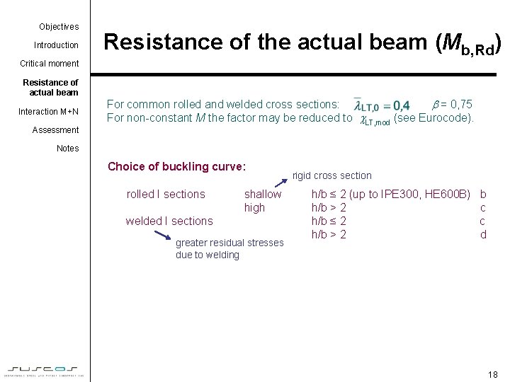
Objectives Introduction Resistance of the actual beam (Mb, Rd) Critical moment Resistance of actual beam Interaction M+N Assessment For common rolled and welded cross sections: = 0, 75 For non-constant M the factor may be reduced to LT, mod (see Eurocode). Notes Choice of buckling curve: rolled I sections shallow high welded I sections greater residual stresses due to welding rigid cross section h/b ≤ 2 (up to IPE 300, HE 600 B) h/b > 2 h/b ≤ 2 h/b > 2 b c c d 18
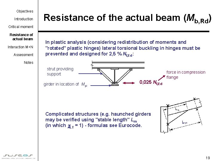
Objectives Introduction Resistance of the actual beam (Mb, Rd) Critical moment Resistance of actual beam Interaction M+N Assessment In plastic analysis (considering redistribution of moments and "rotated" plastic hinges) lateral torsional buckling in hinges must be prevented and designed for 2, 5 % Nf, Ed: Notes strut providing support girder in location of Mpl 0, 025 Nf, Ed Complicated structures (e. g. haunched girders) may be verified using "stable length" Lm (in which LT = 1) - formulas see Eurocode. force in compression flange Lm 19
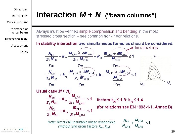
Objectives Introduction Interaction M + N ("beam columns") Critical moment Resistance of actual beam Interaction M+N Assessment Always must be verified simple compression and bending in the most stressed cross section – see common non-linear relations. In stability interaction two simultaneous formulas should be considered: for class 4 only Notes N Mz My Usual case M + Ny: factors kyy ≤ 1, 8; kzy ≤ 1, 4 (for relations see EN 1993 -1 -1, Annex B) Note: historical unsuitable linear relationship (without 2 nd order factors kyy, kzy) 20
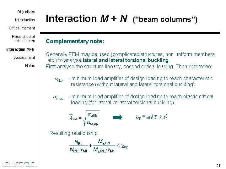
Objectives Introduction Interaction M + N ("beam columns") Critical moment Resistance of actual beam Complementary note: Interaction M+N Assessment Notes Generally FEM may be used (complicated structures, non-uniform members etc. ) to analyse lateral and lateral torsional buckling. First analyse the structure linearly, second critical loading. Then determine: ult, k - minimum load amplifier of design loading to reach characteristic resistance (without lateral and lateral-torsional buckling); cr, op - minimum load amplifier of design loading to reach elastic critical loading (for lateral torsional buckling). op = min( , LT) Resulting relationship: 21
Objectives Introduction Critical moment Resistance of actual beam Interaction M+N Assessment Notes Assessment • Ideal and actual beam – differences. • Procedure for determining of critical moment. • Destabilizing and stabilizing loading. • Approximate approach for lateral torsional buckling. • Resistance of actual beam. • Interaction M+N according to Eurocode. 22
Objectives Introduction Notes to users of the lecture Critical moment Resistance of actual beam Interaction M+N Assessment • This session requires about 90 minutes of lecturing. • Within the lecturing, design of beams subjected to lateral torsional buckling is described. Calculation of critical moment under general loading and entry data is shown. Finally resistance of actual beam and design under interaction of moment and axial force in accordance with Eurocode 3 is presented. • Further readings on the relevant documents from website of www. access-steel. com and relevant standards of national standard institutions are strongly recommended. • Keywords for the lecture: Notes lateral torsional instability, critical moment, ideal beam, real beam, destabilizing loading, imposed axis, beam resistance, stability interaction.
Objectives Introduction Notes for lecturers Critical moment Resistance of actual beam Interaction M+N Assessment Notes • Subject: Lateral torsional buckling of beams. • Lecture duration: 90 minutes. • Keywords: lateral torsional instability, critical moment, ideal beam, real beam, destabilizing loading, imposed axis, beam resistance, stability interaction. • Aspects to be discussed: Ideal beam and real beam with imperfections. Stability and strength. Critical moment and factors which influence its determination. Eurocode approach. • After the lecturing, calculation of critical moments under various conditions or relevant software should be practised. • Further reading: relevant documents www. access-steel. com and relevant standards of national standard institutions are strongly recommended. • Preparation for tutorial exercise: see examples prepared for the course. 24