Lecture1 CE 3180 DESIGN OF STEEL STRUCTURES 1


![Course Outcome 1. recognize the material properties of steel products [POs: e] 2. recognize](https://slidetodoc.com/presentation_image/1c58eb03dcca382a534ce0307ccc6780/image-5.jpg "Course Outcome 1. recognize the material properties of steel products [POs: e] 2. recognize")

 2. Mid-Semester Examination (25%)- 1 Hour")


 1. 5 (DL")


- Slides: 44
Lecture-1 CE – 3180 DESIGN OF STEEL STRUCTURES 1
L – T – P: 3 – 1 – 0 CE 318 N Credits: 4. 0 Unit 1 Properties of Structural Steel, I. S. Rolled Sections, I. S. Specifications, Built up sections, Design philosophy, Introduction to Plastic analysis; Simple cases of beams and frames. Unit 2, Type of Connections, Riveted, Bolted and Welded Connections, Strength, Efficiency and Design of Joints, Modes of Failure of a Joint, Advantages and Disadvantages of Welded Joints, Eccentric Connections. Unit 3 Design of tension members, splicing of tension member, concept of shear lag, use of lug angles. Design of compression members, Beam-column connections. Unit 4. Design of flexure members, Plate girder, Gantry Girder
Text Book S S Duggal “ Design of steel structures” Kazmi S. M. A. and Jindal, R. S. “Design of Steel Structures” PHI, New Delhi, India Reference Books Arya and Ajmani “Design of Steel Structure”, NCB, Roorkee India Ramamrutham “Design of Steel Structures” Dhanpat Rai, Delhi, India. Selected B. I. S Codes I. S. : 800 -2007 -Code of Practice for General Construction in Steel, BIS, New Delhi, India. I. S. Handbook No 1 –list the properties of structural rolled sections IS 875 - provides guidelines for estimating loads.
Course Objectives: To introduce to students theory and application of analysis and design of steel structures. 2. To develop students with an understanding of the behaviour and design of steel members and systems. 3. To prepare students for the effective use of the latest tables, design aids and computer software in the design of steel members.
Course Outcome 1. recognize the material properties of steel products [POs: e] 2. recognize the design philosophy of steel structures and have concept on limit state design [POs: a, e] 3. ability to design bolted and welded connections for tension and compression members and beams. [POs: a, e] 4. apply the principles, procedures and current code requirements to the analysis and design of steel tension members, beams, columns, beamcolumns and connections, Girders [POs: a, c, d, e, i] 5. ability to obtain basic knowledge about the failure mode of steel structure. [POs: a, c, d]
Course Outcome 1. Understanding of the behaviour of structural steel 2. Ability to analyze and design simple bolted and welded connections 3. Ability to perform plastic analysis of simple structures 4. Ability to analyze and design Gantry Girders
Course Assessment Method 1. Assignments and Quizzes (15%) 2. Mid-Semester Examination (25%)- 1 Hour 3. End Semester Examination (60%)- 2 Hours
COURSE POLICIES Attendance policy - Students are expected to attend all the lectures. They are also expected to perform all the work assigned by the teacher. Tardy policy - All the assigned work must be submitted by the due date and time. ◦ Submissions that are 0 - 24 hours late will be penalized for 25% of the marks. ◦ Submissions that are 24 - 48 hours late will be penalized for 50% of the marks. ◦ After 48 hours, submissions will neither be accepted nor graded. ◦ Exceptions can be made for students with emergencies or special circumstances.
STRUCTURE OF A BUILDING Building structure is an assemblage of a group of members expected to support and transmit the loads and forces to the ground. “Tracing the Loads” or “Chasing the Loads” eg. Bridges, Towers, Multi-storey buildings, Storage tanks and Industrial buildings, etc
CARBON STEEL Most popular and effective building material. Carbon Steel is an alloy made by combining iron and other elements the most common of these being carbon. And traces of manganese (1. 65% max), silicon (0. 60% max), and copper (0. 60% max). Carbon Steel is Intermediate stage between wrought iron and cast iron wrought iron- Carbon content less than 0. 05% steel - Carbon content: 0. 05% to 1. 5% cast iron - Carbon content : 2% to 4% 10
VARIETIES OF CARBON STEEL Based on carbon content Mild steel – 0. 05 to 0. 25%(steel sections) Medium carbon steel - High carbon steel - 0. 6 to 1. 5%(cutlery hammers) Increase in carbon content 0. 25 to 0. 6% ( rail wheels) ◦ Increase strength • Decrease ductility and becomes more difficult to weld & lowers the melting point and its temperature resistance in general. 11
Advantages of Steel as Structural Material Handled by trained persons in the factory - better quality control than concrete structures Ø High Strength to weight ratio and can reduce foundation costs Ø High Ductility Ø Environment-friendly-Easily recycled and hence greener than concrete Ø Speed of erection more, Ø Rapid construction in all weathers Ø Demount ability Ø 12
Advantages of Steel as Structural Material • Least Disturbance to Community • Large spans and bay sizes possible, providing more flexibility for owners • Easier to modify and reinforce if architectural changes are made to a facility over its life 13
DISADVANTAGES OF STEEL AS STRUCTURAL MATERIAL Maintenance cost high due to painting Fire-proofing costs Susceptibility to Buckling Reduction in strength due to Fatigue loads Highly skilled labour required 14
STRUCTURAL STEEL MECHANICAL PROPERTIES 15
Material properties Properties of steel required for engg design may be classified as 1. Physical properties 2. Mechanical properties 3. Chemical properties
Physical properties of structural steel, as detailed by cl. 2. 2. 4. 1 of IS 800: 2007, irrespective of its grade may be taken as: a) Unit mass of steel, p = 7850 kg/m 3 b) Modulus of elasticity, E = 2. 0 x 105 N/mm 2 (MPa) c) Poisson ratio, p = 0. 3 d) Modulus of rigidity, G = 0. 769 x 105 N/mm 2 (MPa) e) Coefficient of thermal expansion cx. =12 x 10 6/0 C
MECHANICAL PROPERTIES AS PER IS 800: 2007 18
Mechanical Properties of Structural Steel 2. 2. 4. 2 Principal mechanical properties important to designer are yield stress, ultimate tensile stress, percentage elongation and notch toughness. All except notch toughness are determined from Tensile stress test of specimen. Commonly used properties are summarised in (Table 1 P 13) In general properties that need to be considered by designers when specifying steel construction products are: Strength �Toughness �Ductility �Weldability �Durability.
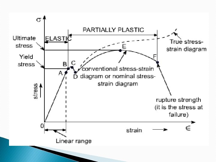
Stress-Strain Relationship in Structural Steel
If a piece of ductile structural steel is subjected to tensile force it will begin elongate. The amount of elongation will increase linearly within certain limits (Hooke’s law). When tensile stress reaches roughly equal to three-fourths of the ultimate strength the elongation will begin to increase at a greater rate without a corresponding increase in the stress
Cold Working & Strain Hardening
25
Structural Steel Characteristics Elasticity: Ability of metal to return to its original shape after loading and subsequent unloading High elasticity Ductility: Ductility is a measure of the degree to which a material can strain or elongate between the onset of yield and eventual fracture under tensile loading High Ductility Toughness: Combination of strength and ductility. If the steel is insufficiently tough, the 'crack' can propagate rapidly, without plastic deformation and result in a 'brittle fracture'. High toughness
Structural Steel Characteristics Weldability: Measured by carbon equivalent, Ceq, as per IS: 2062, 1992, Where C = carbon, Mn = manganese, Cr = chromium, Mo = molybdenum, V = vanadium, Ni = nickel and Cu = copper If carbon content < 0. 12 %, then Ceq can be tolerated up to 0. 45 %
Structural Steel Characteristics Corrosion: Susceptible to Corrosion when exposed to air and water 0. 075 mm/year of the thickness may be lost due to corrosion. Use paints, or weathering steels Fireproofing: Strength reduces with increased temperature Fireproofing required (Section 16 of code) Fatigue: The damage and failure of materials under cyclic loads is called fatigue damage. Section 13 of code
Structural Steel Characteristics hardness – the property of being rigid and resistant to pressure; not easily scratched machinability – the property of a material that can be shaped by hammering, pressing, rolling
MECHANICAL PROPERTIES The number after Fe is characteristic ultimate tensile strength in MPa; Letter A, B, C indicate the grade of steel. Grade A to be used in structures subjected to normal conditions Grade B to be used in structures subjected to non critical applications, where temp does not fall below zero degree celcius. Prone to brittle failure. Grade C for structures at low temp ( upto minus 40 degree celcius) and impact
DESIGN PHILOSPHY
Three Major Design Philosophies A design philosophy is a set of assumptions and procedures which are used to meet the conditions of serviceability, safety, economy and functionality of the structure i. Working stress Method(WSM)/ Allowable Stress Design (ASD) Ultimate Load Method (ULM) Limit State Method(LSM) ii. iii.
Working Stress Method/ Allowable Stress Design The main assumption in the WSM is that the behaviour of structural material is restricted with in linear-elastic region and the safety of it is ensured by restricting the stresses coming on the members by working loads. Thus the allowable stresses will come in the linear portion (i. e. , initial phase) of the stress-strain curve. Thus a factor of safety was introduced to the design.
Working Stress Method/ Allowable Stress Design WSM cannot account for loads acting simultaneously, but has different degrees of uncertainty. It cannot account for the loads having counteracting effects, such as dead load and wind load. The above will lead to non-conservative design. Working Stress method will lead to large FOS and over-sized sections, thus reducing the design economy.
Ultimate Load Method This is also known as load factor method In this we make use of the nonlinear region of stress strain curves of steel and concrete. The safety is ensured by introducing load factor. The ULM makes it possible to consider the effects of different loads acting simultaneously thus solving the shortcomings of WSM. As the ultimate strength of the material is considered we will get much slender sections for columns and beams compared to WSM method.
Ultimate Load Method But the serviceability criteria is not met because of large deflections and cracks in the sections. The fall-back in the method was that even though the nonlinear stress strain behaviour of was considered sections but the nonlinear analysis of the structural was not carried out for the load effects. Thus the stress distribution at ultimate load was just the magnification of service load by load factor following the linear elastic theory.
Limit State Mewthod Limit state is the state of impending failure, beyond which a structure ceases to perform its intended function satisfactorily, in terms of either safety or serviceability. ” There are 2 types of limit states Ultimate Limit State: It considers strength, overturning, fatigue, sliding etc. Serviceability Limit State: It considers crack width, deflection, vibration etc.
Limit state method will be used. The objective of the design is to achieve a structure that will remain fit for use during its life with acceptable target reliability. In other words, the probability of a limit state being reached during its lifetime should be very low. In the limit state method reliability based analysis is performed and based on a particular dependability safety factors are calculated. Two types of safety factors are used Partial Safety factor-Loads Partial Safety factor-materials
Table 4 Partial Safety factor-Loads, f PARTIAL SAFETY FACTORS FOR LOADS ACCOUNTS FOR possibility of Deviation of load from characteristic values. possibility of Inaccurate assessment of loads. possibility in Uncertainty in assessment of load effects. (static/ dynamic) Uncertainity in the lmit state being considered (servicibility
Partial Safety factor-Material, m PARTIAL SAFETY FACTOR FOR MATERIAL strength ACCOUNTS FOR Possibility of unfavorable deviation of material strength from the characteristic value, Possibility of unfavorable variation of member sizes, Possibility of unfavorable reduction in member strength due to fabrication and tolerances, and Uncertainty in the calculation of strength of the members.
3. 5 Load Combinations The following combination of loads with appropriate partial safety factors (see Table 4) maybe considered. a) Dead load + imposed load, b) Dead load + imposed load + wind or earthquake load, c) Dead load + wind or earthquake load, and d) Dead load+ erection load. NOTE — In the case of structures supporting crmres, imposed loads shall include the crane effects as given in 3. 5. 4.
Load Combinations In general consider the 8 - load combinations: (1) 1. 5 (DL + IL) + 1. 05(CL or SL) (2) 1. 2 (DL + IL) + 1. 05(CL or SL) ± 0. 6(WL or EL) (3) 1. 2 (DL + IL ± WL or EL) + 0. 53 (CL or SL) (4) 1. 5(DL ± WL or EL) (5) 0. 9 DL ± 1. 5 (WL or EL) (6) 1. 2 (DL + ER) (7) 0. 9 DL + 1. 2 ER (8) DL + 0. 35(IL + CL or SL) + AL Where, DL = Dead load, IL = imposed load (live load), WL = wind load, SL = snow load, CL = crane load (vertical / horizontal), AL = accidental load, ER = erection load and EL = earthquake load. 42
Design Load/Factored Load A load value obtained by multiplying the characteristic loads by the relevant factors, given in Table 4, to get the design loads or design load effects.
5. 4. 1 Design Strength The Design Strength, is obtained from ultimate strength, and partial safety factors for materials, given in Table 5 as Sd= Sa(ultimate strength)/ Υm where partial safety factor for materials,