
68402 Structural Design of Buildings II 61420 Design

68402: Structural Design of Buildings II 61420: Design of Steel Structures 62323: Architectural Structures II Design of Beam-Columns l l Monther Dwaikat Assistant Professor Department of Building Engineering An-Najah National University 68402 Slide # 1
Beam-Column - Outline l Beam-Columns l Moment Amplification Analysis l Second Order Analysis l Compact Sections for Beam-Columns l Braced and Unbraced Frames l Analysis/Design of Braced Frames l Analysis/Design of Unbraced Frames l Design of Bracing Elements 68402 2
Design for Flexure – LRFD Spec. l Commonly Used Sections: • I – shaped members (singly- and doubly-symmetric) • Square and Rectangular or round HSS 68402 3
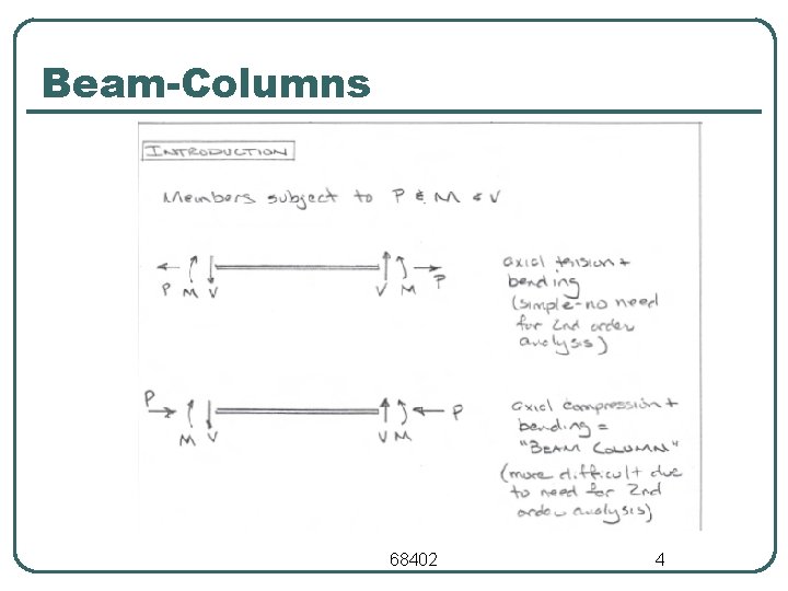
Beam-Columns 68402 4

Beam-Columns 68402 5
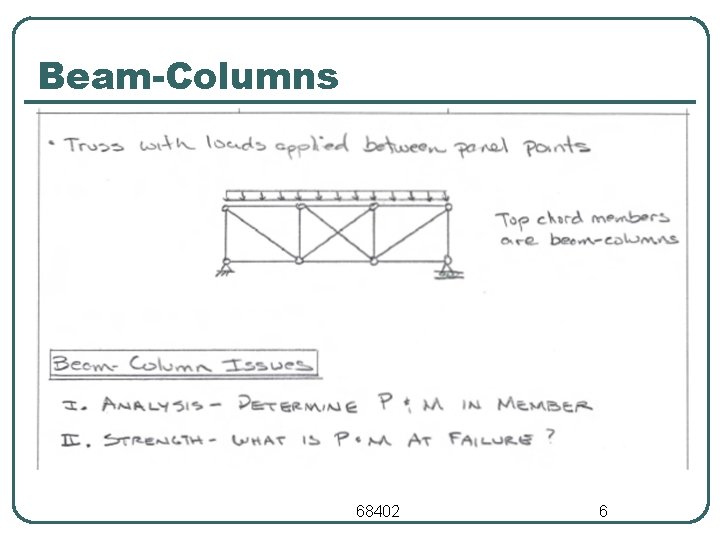
Beam-Columns 68402 6
Beam-Columns 68402 7
Beam-Columns 68402 8
Beam-Columns 68402 9
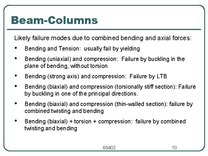
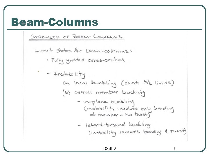
Beam-Columns Likely failure modes due to combined bending and axial forces: • • Bending and Tension: usually fail by yielding • • Bending (strong axis) and compression: Failure by LTB • Bending (biaxial) and compression (thin-walled section): failure by combined twisting and bending • Bending (biaxial) + torsion + compression: failure by combined twisting and bending Bending (uniaxial) and compression: Failure by buckling in the plane of bending, without torsion Bending (biaxial) and compression (torsionally stiff section): Failure by buckling in one of the principal directions. 68402 10

Beam-Columns q Structural elements subjected to combined flexural moments and axial loads are called beam-columns q The case of beam-columns usually appears in structural frames q The code requires that the sum of the load effects be smaller than the resistance of the elements q Thus: a column beam interaction can be written as q This means that a column subjected to axial load and moment will be able to carry less axial load than if no moment would exist. 68402 11
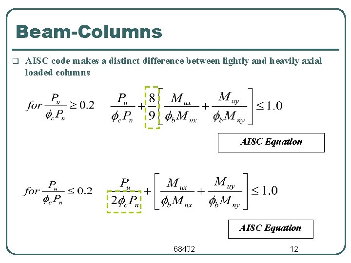
Beam-Columns q AISC code makes a distinct difference between lightly and heavily axial loaded columns AISC Equation 68402 12
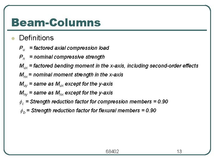
Beam-Columns l Definitions Pu = factored axial compression load Pn = nominal compressive strength Mux = factored bending moment in the x-axis, including second-order effects Mnx = nominal moment strength in the x-axis Muy = same as Mux except for the y-axis Mny = same as Mnx except for the y-axis c = Strength reduction factor for compression members = 0. 90 b = Strength reduction factor flexural members = 0. 90 68402 13
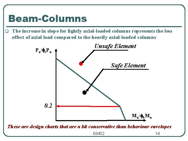
Beam-Columns q The increase in slope for lightly axial-loaded columns represents the less effect of axial load compared to the heavily axial-loaded columns Pu /fc Pn Unsafe Element Safe Element 0. 2 Mu /fb Mn These are design charts that are a bit conservative than behaviour envelopes 68402 14
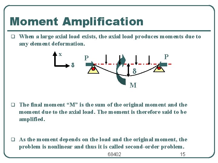
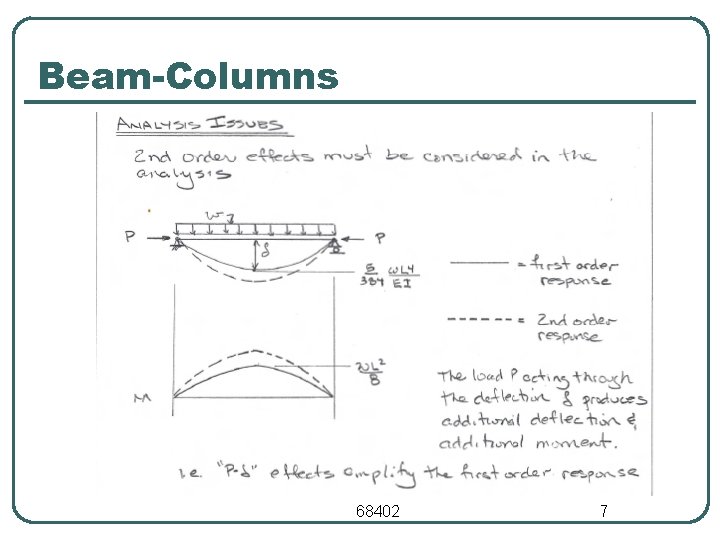
Moment Amplification q When a large axial load exists, the axial load produces moments due to any element deformation. x d P P d M q The final moment “M” is the sum of the original moment and the moment due to the axial load. The moment is therefore said to be amplified. q As the moment depends on the load and the original moment, the problem is nonlinear and thus it is called second-order problem. 68402 15
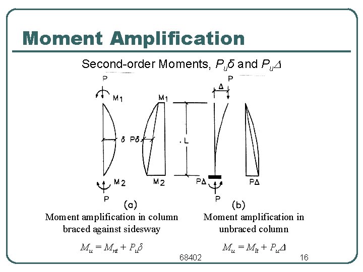
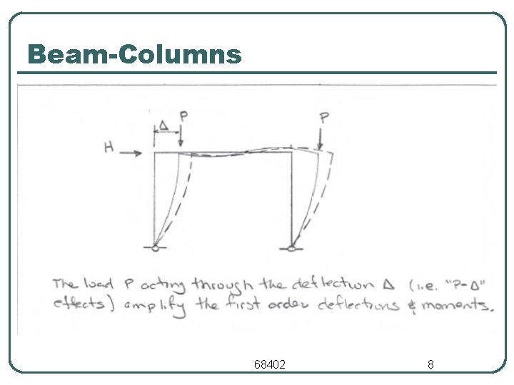
Moment Amplification Second-order Moments, Puδ and Pu Moment amplification in column braced against sidesway Moment amplification in unbraced column Mu = Mnt + Puδ Mu = Mlt + Pu 68402 16
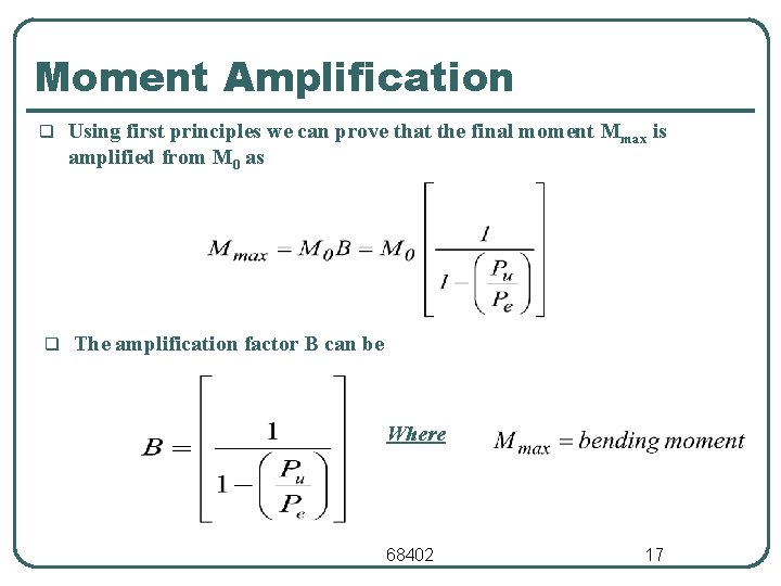
Moment Amplification q q Using first principles we can prove that the final moment Mmax is amplified from M 0 as The amplification factor B can be Where 68402 17
Second Order Analysis 68402 18
Second Order Analysis 68402 19
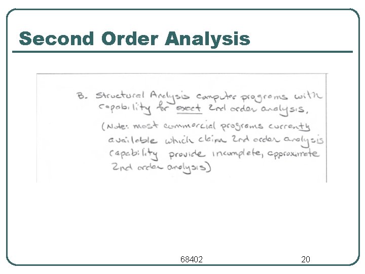
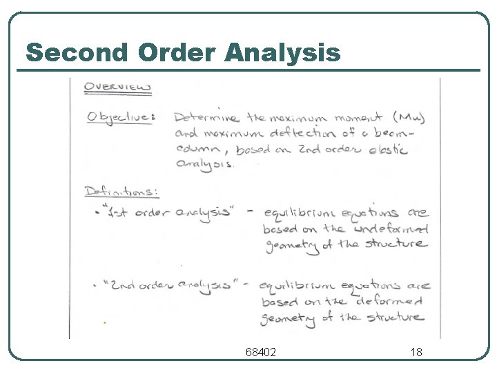
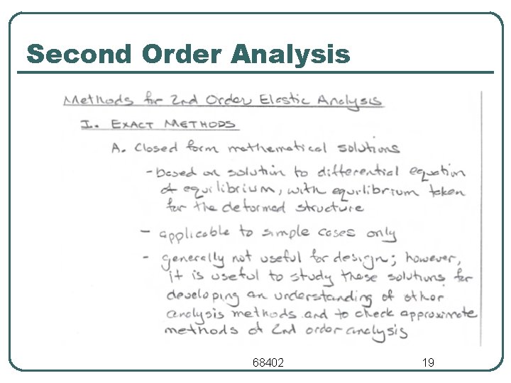
Second Order Analysis 68402 20
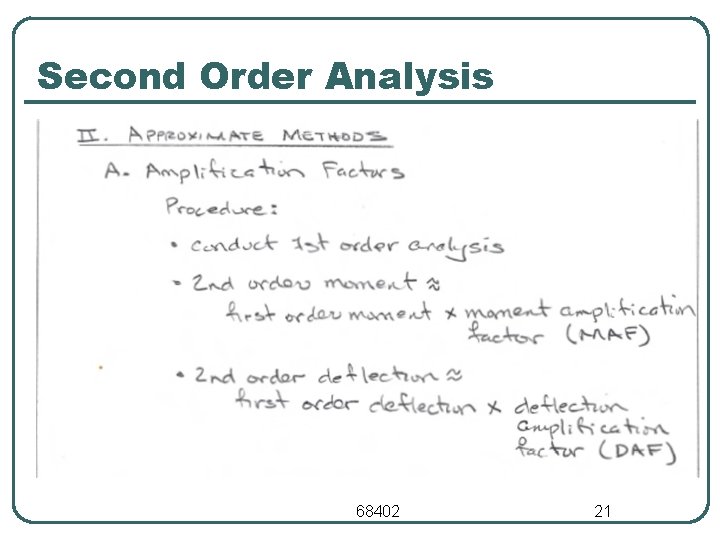
Second Order Analysis 68402 21
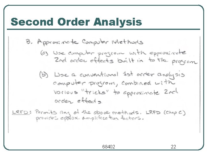
Second Order Analysis 68402 22
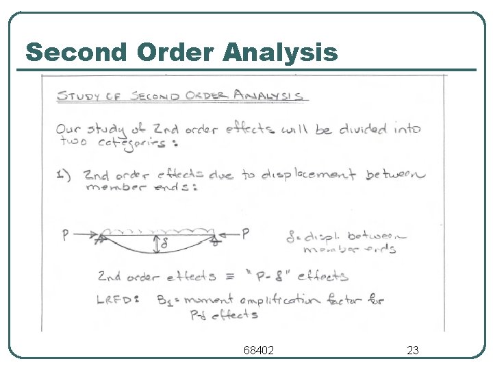
Second Order Analysis 68402 23
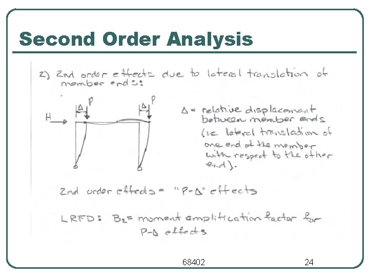
Second Order Analysis 68402 24
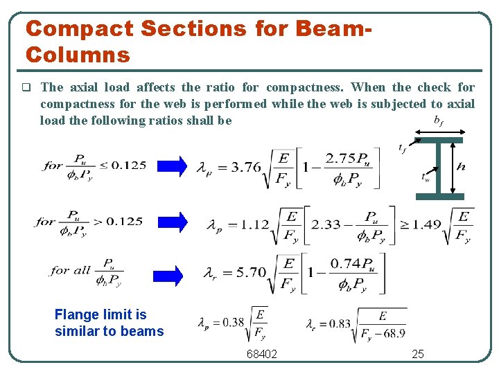
Compact Sections for Beam. Columns q The axial load affects the ratio for compactness. When the check for compactness for the web is performed while the web is subjected to axial load the following ratios shall be Flange limit is similar to beams 68402 25
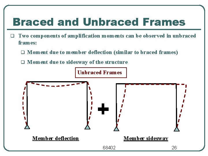
Braced and Unbraced Frames q Two components of amplification moments can be observed in unbraced frames: q Moment due to member deflection (similar to braced frames) q Moment due to sidesway of the structure Unbraced Frames Member deflection Member sidesway 68402 26
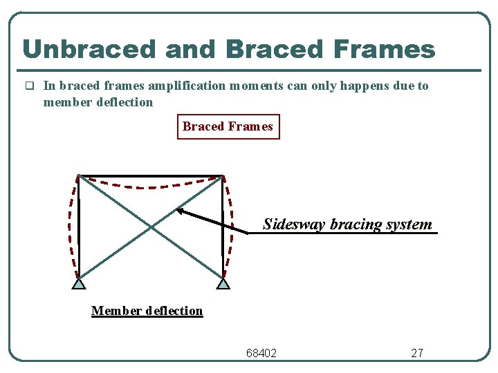
Unbraced and Braced Frames q In braced frames amplification moments can only happens due to member deflection Braced Frames Sidesway bracing system Member deflection 68402 27
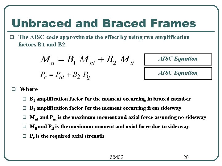
Unbraced and Braced Frames q The AISC code approximate the effect by using two amplification factors B 1 and B 2 AISC Equation q Where q B 1 amplification factor for the moment occurring in braced member q B 2 amplification factor for the moment occurring from sidesway q Mnt and Pnt is the maximum moment and axial force assuming no sidesway q Mlt and Plt is the maximum moment and axial force due to sidesway q Pr is the required axial strength 68402 28
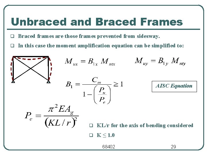
Unbraced and Braced Frames q Braced frames are those frames prevented from sidesway. q In this case the moment amplification equation can be simplified to: AISC Equation q KL/r for the axis of bending considered q K ≤ 1. 0 68402 29
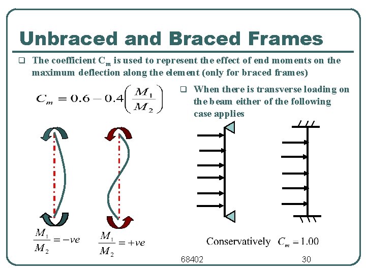
Unbraced and Braced Frames q The coefficient Cm is used to represent the effect of end moments on the maximum deflection along the element (only for braced frames) q When there is transverse loading on the beam either of the following case applies 68402 30
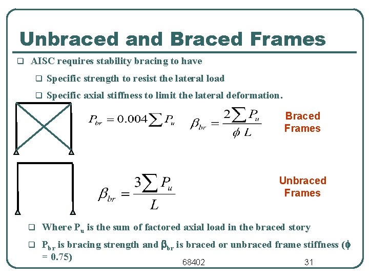
Unbraced and Braced Frames q AISC requires stability bracing to have q Specific strength to resist the lateral load q Specific axial stiffness to limit the lateral deformation. Braced Frames Unbraced Frames q Where Pu is the sum of factored axial load in the braced story q Pbr is bracing strength and bbr is braced or unbraced frame stiffness (f = 0. 75) 68402 31
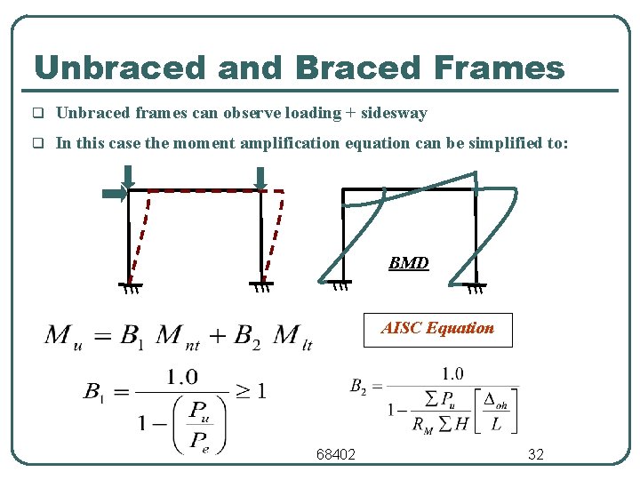
Unbraced and Braced Frames q Unbraced frames can observe loading + sidesway q In this case the moment amplification equation can be simplified to: BMD AISC Equation 68402 32
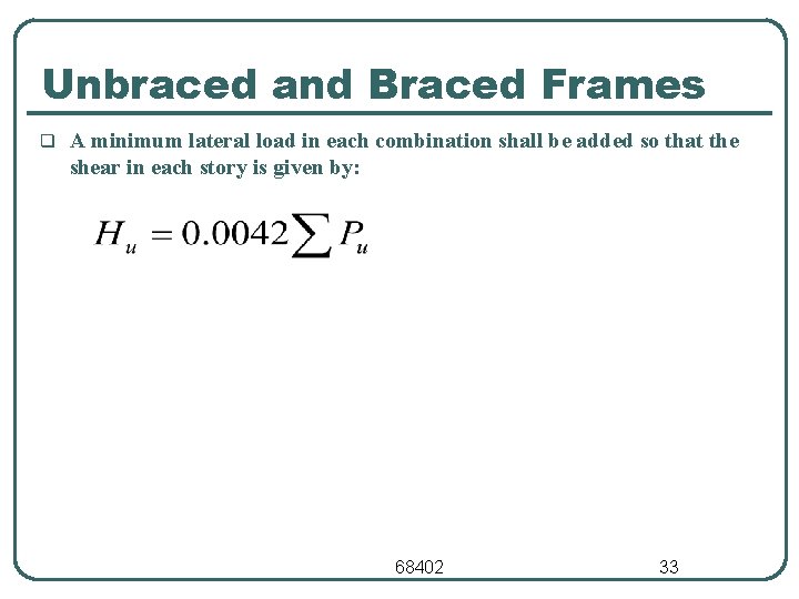
Unbraced and Braced Frames q A minimum lateral load in each combination shall be added so that the shear in each story is given by: 68402 33
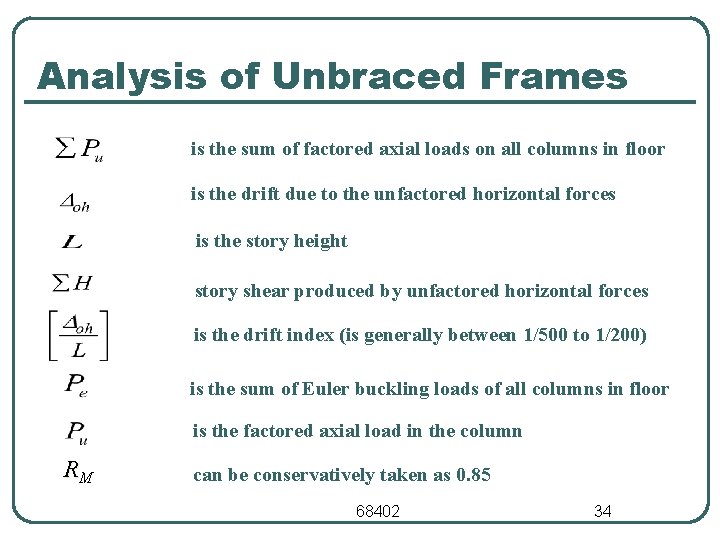
Analysis of Unbraced Frames is the sum of factored axial loads on all columns in floor is the drift due to the unfactored horizontal forces is the story height story shear produced by unfactored horizontal forces is the drift index (is generally between 1/500 to 1/200) is the sum of Euler buckling loads of all columns in floor is the factored axial load in the column RM can be conservatively taken as 0. 85 68402 34
Ex. 5. 1 - Beam-Columns in Braced Frames A 3. 6 -m W 12 x 96 is subjected to bending and compressive loads in a braced frame. It is bent in single curvature with equal and opposite end moments and is not loaded transversely. Use Grade 50 steel. Is the section satisfactory if Pu = 3200 k. N and first-order moment Mntx = 240 k. N. m Step I: From Section Property Table W 12 x 96 (A = 18190 mm 2, Ix = 347 x 106 mm 4, Lp = 3. 33 m, Lr = 14. 25 m, Zx = 2409 mm 3, Sx = 2147 mm 3) 68402 35
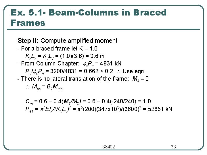
Ex. 5. 1 - Beam-Columns in Braced Frames Step II: Compute amplified moment - For a braced frame let K = 1. 0 Kx. Lx = Ky. Ly = (1. 0)(3. 6) = 3. 6 m - From Column Chapter: c. Pn = 4831 k. N Pu/ c. Pn = 3200/4831 = 0. 662 > 0. 2 Use eqn. - There is no lateral translation of the frame: Mlt = 0 Mux = B 1 Mntx Cm = 0. 6 – 0. 4(M 1/M 2) = 0. 6 – 0. 4(-240/240) = 1. 0 Pe 1 = 2 EIx/(Kx. Lx)2 = 2(200)(347 x 106)/(3600)2 = 52851 k. N 68402 36
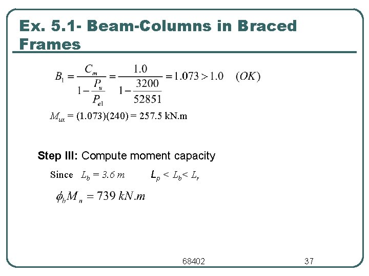
Ex. 5. 1 - Beam-Columns in Braced Frames Mux = (1. 073)(240) = 257. 5 k. N. m Step III: Compute moment capacity Since Lb = 3. 6 m Lp < L b < Lr 68402 37
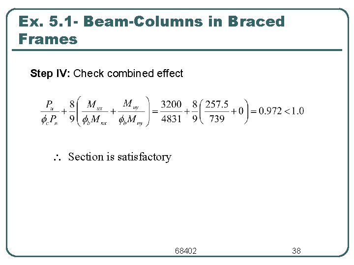
Ex. 5. 1 - Beam-Columns in Braced Frames Step IV: Check combined effect Section is satisfactory 68402 38
Ex. 5. 2 - Analysis of Beam-Column l Check the adequacy of an ASTM A 992 W 14 x 90 column subjected to an axial force of 2200 k. N and a second order bending moment of 400 k. N. m. The column is 4. 2 m long, is bending about the strong axis. Assume: • • ky = 1. 0 Lateral unbraced length of the compression flange is 4. 2 m. 68402 39
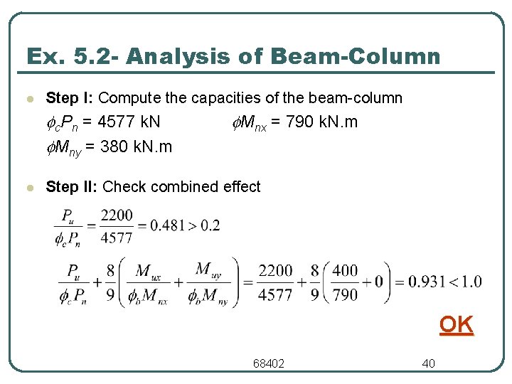
Ex. 5. 2 - Analysis of Beam-Column l Step I: Compute the capacities of the beam-column c. Pn = 4577 k. N Mny = 380 k. N. m l Mnx = 790 k. N. m Step II: Check combined effect OK 68402 40
Design of Beam-Columns l Trial-and-error procedure • Select trial section • Check appropriate interaction formula. • Repeat until section is satisfactory 68402 41
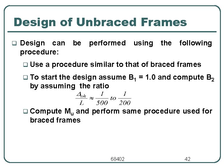
Design of Unbraced Frames q Design can procedure: q Use be performed using the following a procedure similar to that of braced frames q To start the design assume B 1 = 1. 0 and compute B 2 by assuming the ratio q Compute Mu and perform same procedure used for braced frames 68402 42
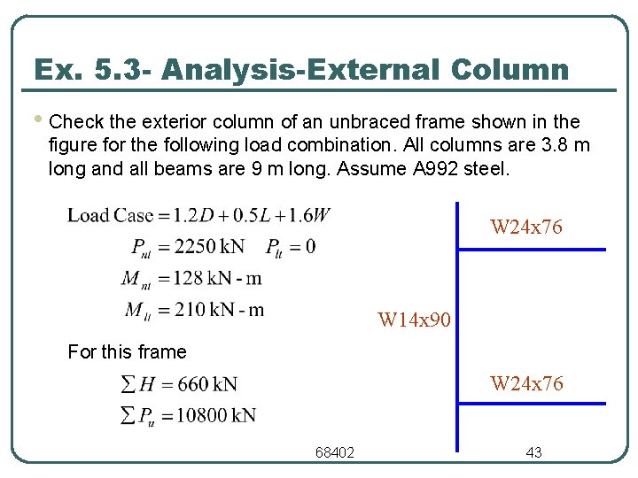
Ex. 5. 3 - Analysis-External Column • Check the exterior column of an unbraced frame shown in the figure for the following load combination. All columns are 3. 8 m long and all beams are 9 m long. Assume A 992 steel. W 24 x 76 W 14 x 90 For this frame W 24 x 76 68402 43
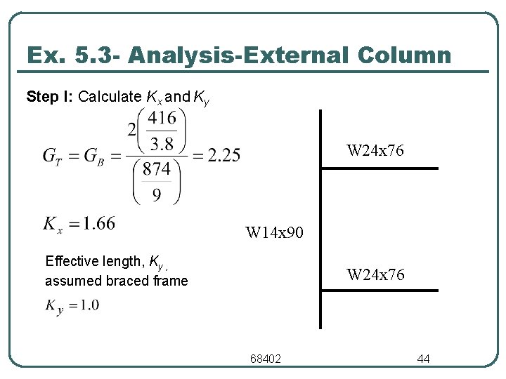
Ex. 5. 3 - Analysis-External Column Step I: Calculate Kx and Ky W 24 x 76 W 14 x 90 Effective length, Ky , assumed braced frame W 24 x 76 68402 44
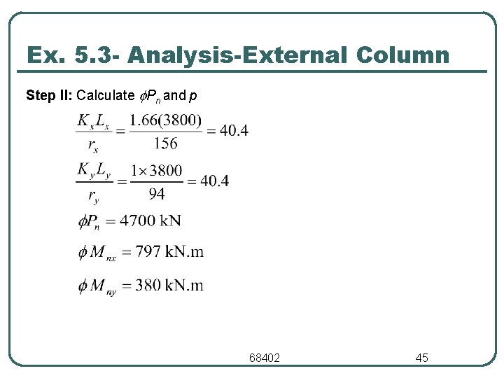
Ex. 5. 3 - Analysis-External Column Step II: Calculate Pn and p 68402 45
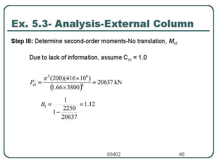
Ex. 5. 3 - Analysis-External Column Step III: Determine second-order moments-No translation, Mnt Due to lack of information, assume Cm = 1. 0 68402 46
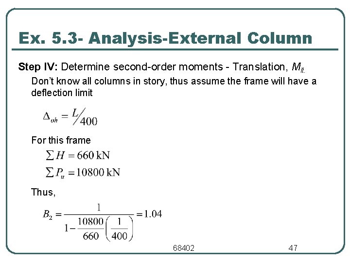
Ex. 5. 3 - Analysis-External Column Step IV: Determine second-order moments - Translation, Mlt. Don’t know all columns in story, thus assume the frame will have a deflection limit For this frame Thus, 68402 47
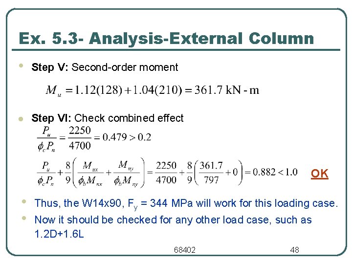
Ex. 5. 3 - Analysis-External Column • Step V: Second-order moment l Step VI: Check combined effect OK • • Thus, the W 14 x 90, Fy = 344 MPa will work for this loading case. Now it should be checked for any other load case, such as 1. 2 D+1. 6 L 68402 48
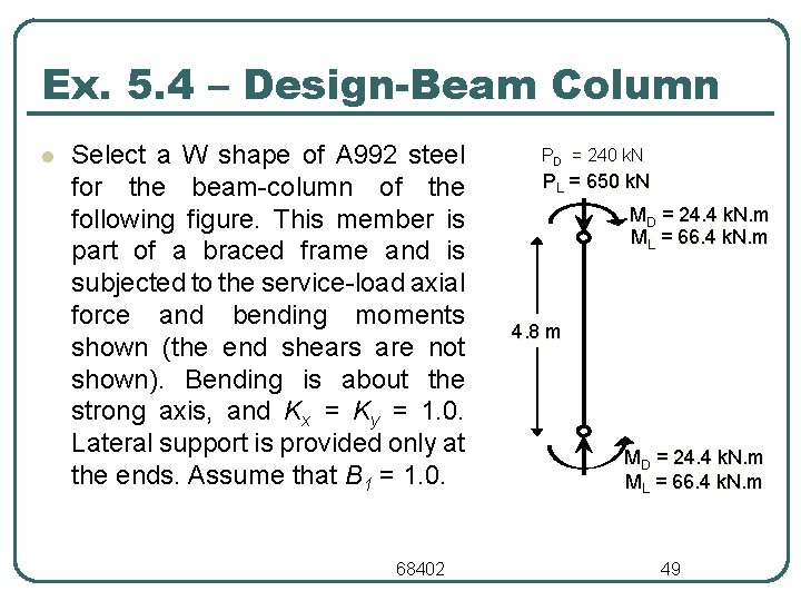
Ex. 5. 4 – Design-Beam Column l Select a W shape of A 992 steel for the beam-column of the following figure. This member is part of a braced frame and is subjected to the service-load axial force and bending moments shown (the end shears are not shown). Bending is about the strong axis, and Kx = Ky = 1. 0. Lateral support is provided only at the ends. Assume that B 1 = 1. 0. 68402 PD = 240 k. N PL = 650 k. N MD = 24. 4 k. N. m ML = 66. 4 k. N. m 4. 8 m MD = 24. 4 k. N. m ML = 66. 4 k. N. m 49
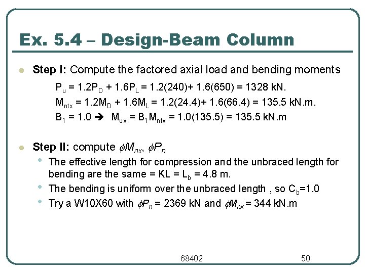
Ex. 5. 4 – Design-Beam Column l Step I: Compute the factored axial load and bending moments Pu = 1. 2 PD + 1. 6 PL = 1. 2(240)+ 1. 6(650) = 1328 k. N. Mntx = 1. 2 MD + 1. 6 ML = 1. 2(24. 4)+ 1. 6(66. 4) = 135. 5 k. N. m. B 1 = 1. 0 Mux = B 1 Mntx = 1. 0(135. 5) = 135. 5 k. N. m l Step II: compute Mnx, Pn • • • The effective length for compression and the unbraced length for bending are the same = KL = Lb = 4. 8 m. The bending is uniform over the unbraced length , so Cb=1. 0 Try a W 10 X 60 with Pn = 2369 k. N and Mnx = 344 k. N. m 68402 50
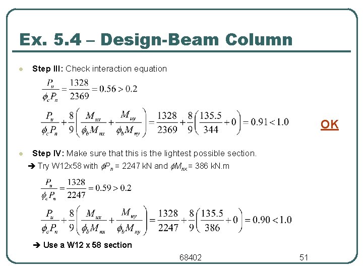
Ex. 5. 4 – Design-Beam Column l Step III: Check interaction equation OK l Step IV: Make sure that this is the lightest possible section. Try W 12 x 58 with Pn = 2247 k. N and Mnx = 386 k. N. m Use a W 12 x 58 section 68402 51
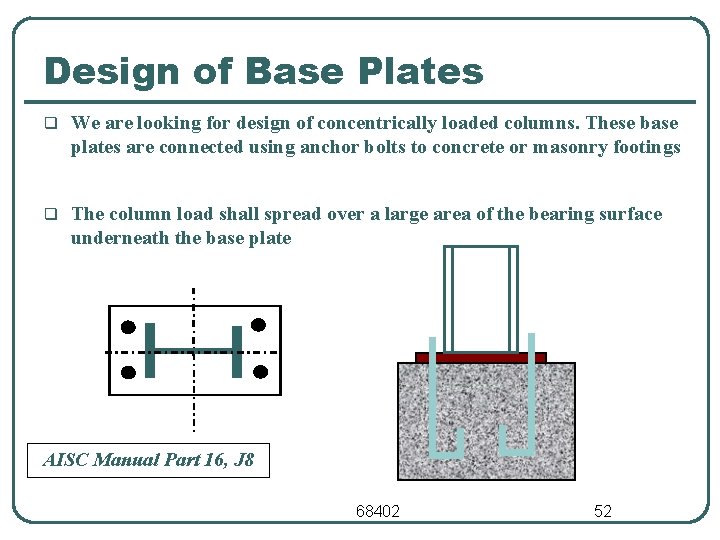
Design of Base Plates q We are looking for design of concentrically loaded columns. These base plates are connected using anchor bolts to concrete or masonry footings q The column load shall spread over a large area of the bearing surface underneath the base plate AISC Manual Part 16, J 8 68402 52
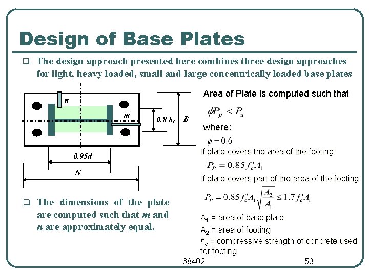
Design of Base Plates q The design approach presented here combines three design approaches for light, heavy loaded, small and large concentrically loaded base plates Area of Plate is computed such that n m 0. 8 bf 0. 95 d N q The dimensions of the plate are computed such that m and n are approximately equal. B where: If plate covers the area of the footing If plate covers part of the area of the footing A 1 = area of base plate A 2 = area of footing f’c = compressive strength of concrete used for footing 68402 53
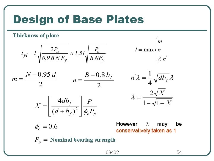
Design of Base Plates Thickness of plate However may be conservatively taken as 1 Nominal bearing strength 68402 54
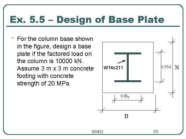
Ex. 5. 5 – Design of Base Plate • For the column base shown in the figure, design a base plate if the factored load on the column is 10000 k. N. Assume 3 m x 3 m concrete footing with concrete strength of 20 MPa. 0. 95 d W 14 x 211 0. 8 bf B 68402 55 N
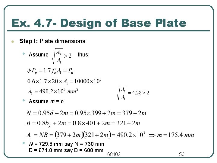
Ex. 4. 7 - Design of Base Plate l Step I: Plate dimensions • Assume m = n • N = 729. 8 mm say N = 730 mm B = 671. 8 mm say B = 680 mm thus: 68402 56
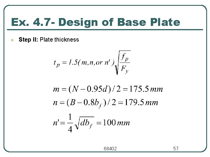
Ex. 4. 7 - Design of Base Plate l Step II: Plate thickness 68402 57
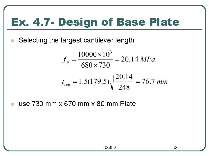
Ex. 4. 7 - Design of Base Plate l Selecting the largest cantilever length l use 730 mm x 670 mm x 80 mm Plate 68402 58
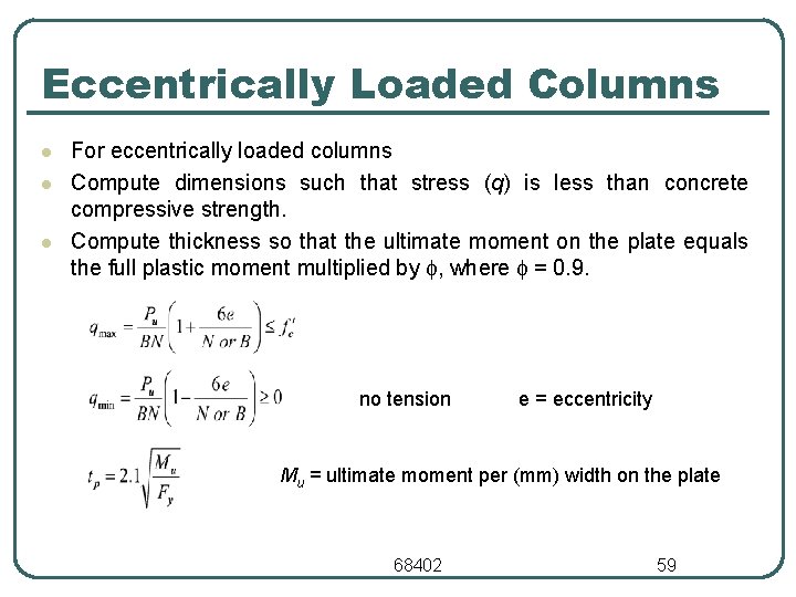
Eccentrically Loaded Columns l l l For eccentrically loaded columns Compute dimensions such that stress (q) is less than concrete compressive strength. Compute thickness so that the ultimate moment on the plate equals the full plastic moment multiplied by , where = 0. 9. no tension e = eccentricity Mu = ultimate moment per (mm) width on the plate 68402 59
- Slides: 59