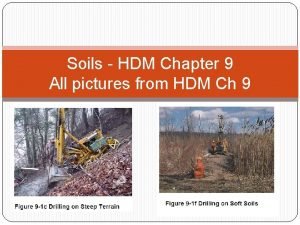
Appurtenances HDM Ch 10 1 Kinetic Energy gforces


- Slides: 34

Appurtenances HDM Ch. 10 1

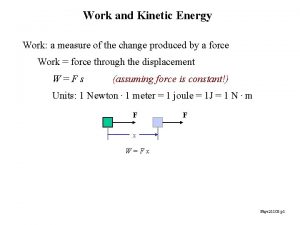
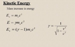
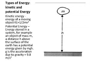
Kinetic Energy (g-forces) n A car weighs 3000 pounds At 20 mph KE=40, 000 ft-lb (0. 5 mv 2) n At 40 mph KE=160, 000 ft-lb n If the car above stops in 50 ft Average deceleration in g’s is 1. 07 for a car starting at 40 mph n n 2

Equations n Kinetic Energy = 0. 5*Mass*V 2 n Avg Deceleration (in g’s) for a car at some initial speed decelerating to a stopping condition over some length L: n V 2/(2*g*L) 3

Appurtenances When vehicles leave the roadway how can you reduce the # and severity of accidents? 4

Clear Zone Area free of hazardous objects and gently graded to permit reasonably safe re-entry to the highway or provide adequate distance for stopping References: AASHTO Green Book AASHTO Roadside Design Guide 5

New & Reconstructed n n Provide satisfactory clear zones when practical and provide barriers if not Clear zone includes: -Shoulder -Recoverable slope (or traversable slope and clear runout width) 6

Clear Zone Based on: n Design Speed n Traffic Volume n Roadside Slope n Curvature of the Road 7

Basic Recovery Width (BRW) Basic width of recovery area that should be provided (see Table 10 -1) BRW does not consider curvature, nonrecoverable slopes or accident history 8

9

Non-Recoverable Slope at which it is unlikely a driver will be able to regain control of a vehicle and return to the roadway (vehicle will continue to the bottom of the slope) Embankment slopes steeper than 1: 4 are considered non-recoverable Traversable, non-recoverable slopes can be present in the clear zone, but do not count towards the BRW 10

Curve-Corrected Recovery Width (CCRW) Takes into account effects of horizontal curvature Obtain by multiplying BRW by the horizontal curve correction factor found in Table 10 -2 Apply factor when long tangents are followed by a curve rated 15 km/hr less than the operating tangent speed 11

12

Clear Runout Width (CRW) Width provided at the toe of a traversable, nonrecoverable fill slope Minimum width should be 2. 5 m (why that #? ) 13

Desired Minimum Clear Zone Width Larger of: n BRW n CCRW n Sum of CCRW plus the width from the traveled way to the toe of the traversable but non-recoverable slope 14

Design Clear Zone Width Should be at least the minimum and preferably greater than the minimum 15

Point of Need Fixed object n use 15 -deg divergence angle n use 10 -deg on freeways/interstates 16

17

Deflection Distance that the outside face line of a barrier will deflect when struck by a vehicle See Table 10 -3 (based on 100 km/hr; 2000 kg vehicle, 25 deg angle) Deflection distance behind barriers must be kept free of FO’s 18

19

Barrier Types n n Cable Guide Rail Corrugated Metal (W-beam) (1. 5*cable) Box Beam (3*cable) Concrete (10*cable) 20

21

22

23

Median Barriers n Designed to withstand impact from either side q q q Corrugated metal beam Box Beam Concrete 24

Selecting Guide Rail n n n Choose barrier w/ largest acceptable deflection Deflection must be less than distance from barrier line to nearest hazard that can’t be removed or relocated Maintain area behind guide railing q n (tree dia. > 100 mm is considered a hazard) Deflections must stay within ROW 25

Potential Hazards n n Potential fatalities: q Cliff q Deep body of water q Flammable liquids tank Fixed Objects: q Bridge piers/abutments q Trees (>100 mm) q Utility Poles q Buildings q Retaining Walls q Overhead sign structures 26

Potential Hazards (continued) n Roadside Obstacles q q q n Rock cuts Longitudinal retaining walls Ditches Cliffs Dropoffs Bodies of Water Projectiles: q q Mailboxes Fence Rails 27

Treatment Options: Remove from clear zone Relocate Modify 1. 2. 3. q q Shield 4. q q 5. Replace concrete headwall w/ flared end Pour a smooth concrete wall against a rock cut Place grates across drain pipe end sections Replace posts w/ break-away posts Guide railing Impact attenuators Delineate 28

Impact Attenuators n n Used when fixed hazards can’t be removed or protected by railing (gore areas) Inertial Systems-Transfers kinetic energy to series of yielding masses (sand barrels) http: //www. crashcushions. com/rental. php http: //epg. modot. org/index. php? title=Category: 612_impact_attenuators 29

Impact Attenuators n Compression Systems-Absorbs energy by progressive deformation or crushing of the system elements (GREAT-Guardrail Energy Absorbing Terminal) http: //www. highwaysafety. net/end. Treatments. htm http: //www. acprod. com. au/images/product/AC P-NSW__SKT_product_brochure_1. jpg 30

Guiderail is a Type 3 Box with a 'WYBET' terminal section. Picture taken in June 2011 Location: Interstate 81 south in the town of Castle Creek, NY---from SUNYIT student who works for NYSDOT 31

Vaulting n When vehicle vaults over a barrier q q n Free to hit a FO May roll over Major Cause (Curbs) q q Don’t use curbs w/ concrete barriers or cable Minimize use of mountable curbs Don’t use non-mountable curbing when operating speeds are >80 km/hr Place curbs <1’ or more than 10’ from guide railing 32

Other n Fencing and cattle passes keep livestock and wild animals from entering the traveled way 33

Innovative Median Barriers: n n Single Slope Concrete Median Barrier Moveable Concrete Barrier Truck Barrier Cable Median Barrier 34
 Street inlets called gullies
 Appurtenances used in water distribution system
 Latham traffic circle
 Modelo hdm
 Spring potential energy
 Gravitational
 Gravitational potential energy vs kinetic energy
 Thermal energy and mass
 Kinetic energy vs potential energy
 Potential enrgy
 Mechanical energy conservation
 Gravitational potential energy
 The change in mechanical energy
 Energy energy transfer and general energy analysis
 Energy energy transfer and general energy analysis
 Acceleration kinetic energy
 Principle of work and kinetic energy
 Relation between pressure and kinetic energy of gas
 Normalizable wave function
 Translational kinetic energy
 Thermal kinetic energy
 Moment of inertia chart
 History of kinetic energy
 Kinetic rotational energy formula
 Linear kinetic energy
 Rotational inertia ap physics 1
 Linear kinetic energy
 Rigid body
 Kinetic energy in volleyball
 Kinetic and potential energy
 Kinetic and potential energy graphic organizer
 Kinetic and potential energy
 Potential energy examples
 Kinetic and potential energy
 Kinetic energy demonstration
