UNIT II SEWER DESIGN UNIT II SEWER DESIGN


 is used to discharge the sewage from a")


 Asbestos Cement Sewers � These are manufactured from a mixture of asbestos fibers,")

 Plain Cement Concrete or Reinforced Cement Concrete �Plain cement concrete (1: 1. 5:")
 PLAIN CEMENT CONCRETE OR REINFORCED CEMENT CONCRETE The reinforcement in these pipes can")


 Vitrified Clay or Stoneware Sewers These pipes are used for house connections as")
 Vitrified Clay or Stoneware Sewers Advantages � Resistant to corrosion, hence fit for")
 Vitrified Clay or Stoneware Sewers Disadvantages �Heavy, bulky and brittle and hence, difficult")
 Brick Sewers �This material is used for construction of large size combined sewer")
 Cast Iron Sewers �These pipes are stronger and capable to withstand greater tensile,")
 Cast Iron Sewers � They form 100% leak proof sewer line to avoid")
 Steel Pipes �These are used under the situations such as pressure main sewers,")
 Steel Pipes �These pipes cannot withstand high external load and these pipes may")
 Ductile Iron Pipes � Ductile iron pipes can also be used for conveying")
 Ductile Iron Pipes �Ductile iron is still believed to be stronger and more")
 Plastic sewers (PVC pipes) �Plastic is recent material used for sewer pipes. These")
 High Density Polythylene (HDPE) PIPES �Use of these pipes for sewers is recent")
 High Density Polythylene (HDPE) PIPES �They offer all the advantages offered by PVC")
 Glass Fiber Reinforced Plastic Pipes � This martial is widely used where corrosion")
 Glass Fiber Reinforced Plastic Pipes Advantages �Light weight of pipes that allows for")
 Glass Fiber Reinforced Plastic Pipes Advantages �Smoothness of the internal wall that minimizes")
 Lead Sewers �They are smooth, soft and can take odd shapes. �This pipe")


 Manholes Shallow manhole")
 Manholes Rectangular manhole for depth 0. 9 m to 2. 5")


 Drop manholes")
 Lamp holes")
 Clean-outs")
 Street inlets called Gullies")
 Catch basins,")
 Inverted Siphons")


- Slides: 103
UNIT II SEWER DESIGN
UNIT II SEWER DESIGN �Sewerage �Hydraulics of flow in sewers �Objectives �Design period �Design of sanitary and storm sewers �Small bore systems �Computer applications �Laying, joining & testing of sewers – appurtenances �Pumps – selection of pumps and pipe Drainage �Plumbing System for Buildings �One pipe and two pipe system.
UNIT II SEWER DESIGN �Sewerage �Objectives of sewage collection and disposal �Definitions �Types of sewerage system �Patterns of collection system
OBJECTIVES OF SEWAGE COLLECTION AND DISPOSAL The objective of sewage collection and disposal is to ensure that Sewage discharged from communities is properly collected, transported, treated to the required degree so as not to cause danger to human health or unacceptable damage to the natural environment and finally disposed off without causing any health or environmental problems.
OBJECTIVES OF SEWAGE COLLECTION AND DISPOSAL Thus, efficient sewerage scheme can achieve the following: � To provide a good sanitary environmental condition of city protecting public health. � To dispose the human excreta to a safe place by a safe and protective means. � To dispose of all liquid waste generated from community to a proper place to prevent a favorable condition for mosquito breeding, fly developing or bacteria growing. � To treat the sewage, as per needs, so as not to endanger the body of water or groundwater or land to get polluted where it is finally disposed off. Thus, it protects the receiving environment from degradation or contamination.
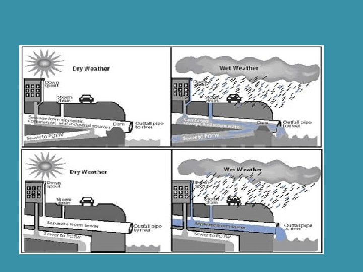
DEFINITIONS �There are three types of sewer systems that are commonly used for sewage collection. �Separate sewers are those which carry the house hold and industrial wastes only. �Storm water drains are those which carry rain water from the roofs and street surfaces. �Combine sewers are those which carry both sewage and storm water together in the same conduit.
SEPARATE SEWERS
STORM WATER DRAINS
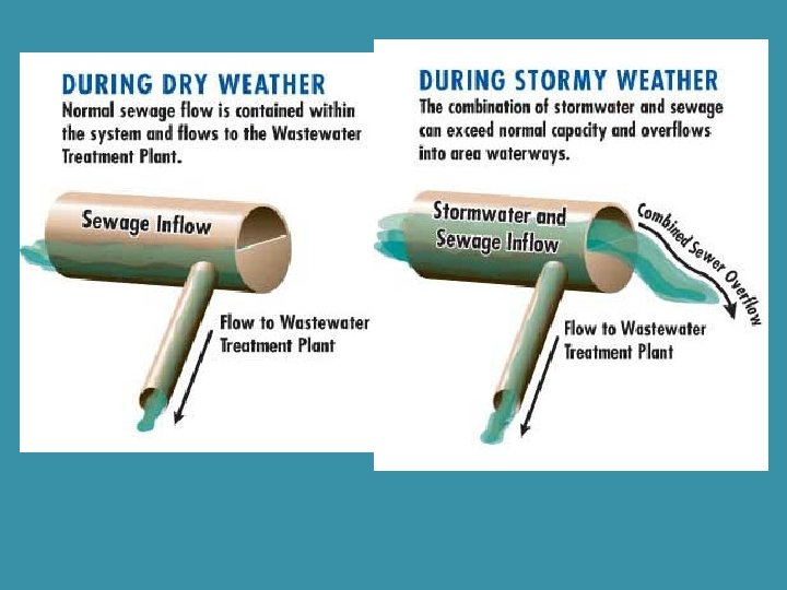
COMBINE SEWERS
DEFINITIONS � House sewer (or drain) is used to discharge the sewage from a building to a street sewer. � Lateral sewer is a sewer which collects sewage directly from the household buildings. � Branch sewer or submain sewer is a sewer which receives sewage from a relatively small area. � Main sewer or trunk sewer is a sewer that receives sewage from many tributary branches and sewers, serving as an outlet for a large territory. � Depressed sewer is a section of sewer constructed lower than adjacent sections to pass beneath an obstacle or obstruction. It runs full under the force of gravity and at greater than atmospheric pressure. The sewage enters and leaves the depressed sewer at atmospheric pressure.
DEFINITIONS �Intercepting sewer is a sewer laid transversely to main sewer system to intercept the dry weather flow of sewage and additional surface and storm water as may be desirable. An intercepting sewer is usually a large sewer, flowing parallel to a natural drainage channel, into which a number of main or outfall sewers discharge. �Outfall sewer receives entire sewage from the collection system and finally it is discharged to a common point. �Relief sewer or overflow sewer is used to carry the flow in excess of the capacity of an existing sewer.
TYPES OF SEWERAGE SYSTEM The sewerage system can be of following three types: �Combined system �Separate System �Partially separate system �Combined system: In combined system along with domestic sewage, the run-off resulting from storms is carried through the same conduit of sewerage system. In countries like India where actual rainy days are very few, this system will face the problem of maintaining self cleansing velocity in the sewers during dry season, as the sewage discharge may be far lower as compared
TYPES OF SEWERAGE SYSTEM �Separate System: In separate system, separate conduits are used; one carrying sewage and other carrying storm water run-off. The storm water collected can be directly discharged into the water body since the run-off is not as foul as sewage and no treatment is generally provided. Whereas, the sewage collected from the city is treated adequately before it is discharged into the water body or used for irrigation to meet desired standards. Separate system is advantageous and economical for big towns.
TYPES OF SEWERAGE SYSTEM �Partially separate system: In this system part of the storm water especially collected from roofs and paved courtyards of the buildings is admitted in the same drain along with sewage from residences and institutions, etc. The storm water from the other places is collected separately using separate storm water conduits.
SEPARATE SYSTEM
COMBINED SYSTEM
Advantages of combined system �In an area where rainfall is spread throughout a year, there is no need of flushing of sewers, as self cleansing velocity will be developed due to more quantity because of addition of storm water. �Only one set of pipe will be required for house plumbing. �In congested areas it is easy to lay only one pipe rather than two pipes as required in other systems.
disadvantages of combined system �Not suitable for the area with small period of rainfall in a year, because dry weather flow will be small due to which self cleansing velocity may not develop in sewers, resulting in silting. �Large flow is required to be treated at sewage treatment plant before disposal, hence resulting in higher capital and operating cost of the treatment plant. �When pumping is required this system is uneconomical. �During rains overflowing of sewers will spoil public hygiene.
�As Advantages of separate system sewage flows in separate pipe, hence the quantity to be treated at sewage treatment plant is small, resulting in economy of treatment. �This system may be less costly as only sanitary sewage is transported in closed conduit and storm water can be collected and conveyed through open drains. �When pumping is required during disposal, this system is economical due to less flow.
disadvantages of separate system �Self cleansing velocity may not developed at certain locations in sewers and hence flushing of sewers may be required. �This system requires laying two sets of pipe, which may be difficult in congested area. �This system will require maintenance of two sets of pipelines and hence maintenance cost is more.
Advantages of partially separate system �Economical and reasonable size sewers are required. �Work of house plumbing is reduced as rain water from roofs, sullage from bathrooms and kitchen, etc. are combined with discharge from water closets. �Flushing of sewers may not be required as small portion of storm water is allowed to enter in sanitary sewage.
disadvantages of partially separate system �Increased cost of pumping as compared to separate system at treatment plants and intermediate pumping station wherever required. �In dry weather self-cleansing velocity may not develop in the sewers.
CONSIDERATIONS FOR THE TYPE OF SYSTEM Following points are considered before finalizing the type of collection system. �The separate system requires laying of two sets of conduits whereas in combined system only one bigger size conduit is required. �Laying of two separate conduits may be difficult in the congested streets. �In combined system sewers are liable for silting during non-monsoon season, hence they are required to be laid at steeper gradients. Steeper gradients for the sewers may require more number of pumping stations, particularly for flat terrain, which may make the system costly.
CONSIDERATIONS FOR THE TYPE OF SYSTEM �Large quantity of wastewater is required to be treated before discharge in case of combined system. Hence, large capacity treatment plant is required. �In separate system, only sewage is treated before it is discharged into natural water body or used for irrigation. No treatment is generally given to the rainwater collected before it is discharge in to natural water body. �In case of separate system pumping is only required for sewage. Pumping can be avoided for storm water lines, as they are not very deep and normally laid along the natural slopes.
CONSIDERATIONS FOR THE TYPE OF SYSTEM �In combined system large capacity pumping station is required to safely handle the flow that is likely to be generated during highest design storm considered. �Based on site conditions the economy of the system needs to be evaluated and selection is made accordingly.
PATTERNS OF COLLECTION SYSTEM �The network of sewers consists of house sewers discharging the sewage to laterals. The lateral discharges the sewage into branch sewers or sub-mains and submains discharge it into main sewer or trunk sewer. The trunk sewer carries sewage to the common point where adequate treatment is given to the sewage and then it is discharged.
PATTERNS OF COLLECTION SYSTEM The patterns of collection system depend upon: 1. topographical and hydrological features of the area. 2. location and methods of treatment and disposal works. 3. type of sewerage system employed 4. Extent of area to be served. Types of pattern a. Perpendicular pattern b. Interceptor pattern c. Radial Pattern d. Fan Pattern e. Zone Pattern
a. Perpendicular pattern � The shortest possible path is maintained for the rains carrying storm water and sewage � It is suitable for separate system and partially separate system for storm water drains. � This pattern is not suitable for combined system, because treatment plant is required to be installed at many places; otherwise it will pollute the water body where the sewage is discharged.
b. Interceptor pattern �Sewers are intercepted with large size sewers �Interceptor carries sewage to a common point, where it can be disposed off with or without �treatment. �Overflows should be provided to handle very large flow.
c. Radial Pattern � It is suitable for land disposal. � In this pattern sewers are laid radialy outwards from the centre, hence this pattern is called as radial pattern. � The drawback in this pattern is more number of disposal works are required.
d. Fan Pattern This pattern is suitable for a city situated at one side of the natural water body, such as river. � The entire sewage flows to a common point where one treatment plant is located � In this number of converging main sewers and sub-mains are used forming a fan shape. Single treatment plant is required in this pattern. � The drawback in this pattern is that larger diameter sewer is required near to the treatment plant as entire sewage is collected at a common point. � In addition, with new development of the city the load on existing treatment plant increases. �
e. Zone Pattern �More numbers of interceptors are provided in this pattern �This pattern is suitable for sloping area than flat areas.
UNIT II SEWER DESIGN �Sewerage �Hydraulics of flow in sewers �Objectives �Design period �Design of sanitary and storm sewers �Small bore systems �Computer applications �Laying, joining & testing of sewers – appurtenances �Pumps – selection of pumps and pipe Drainage �Plumbing System for Buildings �One pipe and two pipe system.
Design period The future period for which the provision is made in designing the capacities of the various components of the sewerage scheme is known as the design period. The design period depends upon the following: �Ease and difficulty in expansion, �Amount and availability of investment, �Anticipated rate of population growth, including shifts in communities, industries and commercial investments, �Hydraulic constraints of the systems designed, and �Life of the material and equipment.
Design period Following design period can be considered for different components of sewerage scheme. � 1. Laterals less than 15 cm diameter : Full development � 2. Trunk or main sewers : 40 to 50 years � 3. Treatment Units : 15 to 20 years � 4. Pumping plant : 5 to 10 years
Design Discharge of Sanitary �The total quantity of sewage generated per day is estimated as Sewage product of forecasted population at the end of design period considering per capita sewage generation and appropriate peakfactor. �The per capita sewage generation can be considered as 75 to 80% of the per capita water supplied per day. �The increase in population also result in increase in per capita water demand hence, per capita production of sewage. �This increase in water demand occurs due to increase in living standards, betterment in economical condition, changes in habit of people, and enhanced demand for public utilities.
Factors Considered for Selecting Material for Sewer Following factors should be considered before selecting material for manufacturing sewer pipes: a. Resistance to corrosion � Sewer carries wastewater that releases gases such as H 2 S. This gas in contact with moisture can be converted into sulfuric acid. The formation of acids can lead to the corrosion of sewer pipe. � Hence, selection of corrosion resistance material is must for long life of pipe. b. Resistance to abrasion � Sewage contain considerable amount of suspended solids, part of which are inorganic solids such as sand or grit. These particles moving at high velocity can cause wear and tear of sewer pipe internally. This abrasion can reduce thickness of pipe and reduces hydraulic efficiency of the sewer by making the interior surface rough.
Factors Considered for Selecting Material for Sewer c. Strength and durability �The sewer pipe should have sufficient strength to withstand all the forces �Sewers are subjected to considerable external loads of backfill material and traffic load, if any. They are not subjected to internal pressure of water. To withstand external load safely without failure, sufficient wall thickness of pipe or reinforcement is essential. In addition, the material selected should be durable and should have sufficient resistance against natural weathering action to provide longer life to the pipe.
Factors Considered for Selecting Material for Sewer d. Weight of the material �The material selected for sewer should have less specific weight, which will make pipe light in weight. The lightweight pipes are easy for handling and transport. e. Imperviousness �To eliminate chances of sewage seepage from sewer to surrounding, the material selected for pipe should be impervious. f. Economy and cost g. Hydraulically efficient �The sewer shall have smooth interior surface to have less frictional coefficient.
Materials for Sewer Asbestos Cement Sewers 2. Plain Cement Concrete or Reinforced Cement Concrete 3. Vitrified Clay or Stoneware Sewers 1.
1) Asbestos Cement Sewers � These are manufactured from a mixture of asbestos fibers, silica and cement. Asbestos fibers are thoroughly mixed with cement to act as reinforcement. � Size 10 to 100 cm internal diameter and length up to 4. 0 m. � These pipes can be easily assembled without skilled labour with the help of special coupling, called ‘Ring Tie Coupling’ or Simplex joint. � The pipe and joints are resistant to corrosion and the joints are flexible to permit 12 o deflection for curved laying. � These pipes are used for vertical transport of water. For example, transport of rainwater from roofs in multistoried buildings, for transport of sewage to grounds, and for transport of less foul sullage i. e. , wastewater from kitchen and bathroom.
Asbestos Cement Sewers Advantages �These pipes are light in weight and hence, easy to carry and transport. �Easy to cut and assemble without skilled labour. �Interior is smooth (Manning’s n = 0. 011) hence, can make excellent hydraulically efficient sewer. Disadvantages �These pipes are structurally not very strong. are susceptible to corrosion by sulphuric acid. When bacteria produce H 2 S, in presence of water, H 2 SO 4 can be formed leading to corrosion of pipe material.
2) Plain Cement Concrete or Reinforced Cement Concrete �Plain cement concrete (1: 1. 5: 3) pipes are available up to 0. 45 m diameter and reinforcement �Cement pipes are available up to 1. 8 m diameter. These pipes can be cast in situ or precast pipes. �Precast pipes are better in quality than the cast in situ pipes.
2) PLAIN CEMENT CONCRETE OR REINFORCED CEMENT CONCRETE The reinforcement in these pipes can be different such as �single cage reinforced pipes, used for internal pressure < 0. 8 m; �double cage reinforced pipes used for both internal and external pressure > 0. 8 m; �elliptical cage reinforced pipes are used for larger diameter sewers subjected to external pressure �and Hume pipes with steel shells coated with concrete from inside and outside. Nominal longitudinal reinforcement of 0. 25% is provided in these pipes.
Plain Cement Concrete or Reinforced Advantages Cement Concrete � Strong in tension as well as compression. � Resistant � They to erosion and abrasion. can be made of any desired strength. � Easily molded, and can be in situ or precast pipes. � Economical � These for medium and large sizes. pipes are available in wide range of size and the trench can be opened and backfilled rapidly during maintenance of sewers.
Plain Cement Concrete or Reinforced Cement Concrete Disadvantages �These pipes can get corroded and pitted by the action of H 2 SO 4. �The carrying capacity of the pipe reduces with time because of corrosion. �The pipes are susceptible to erosion by sewage containing silt and grit. �The concrete sewers can be protected internally by vitrified clay linings. With protection lining they are used for almost all the branch and main sewers. Only high alumina cement concrete should be used when pipes are exposed to corrosive liquid like sewage.
3) Vitrified Clay or Stoneware Sewers These pipes are used for house connections as well as lateral sewers. �The size of the pipe available is 5 cm to 30 cm internal diameter with length 0. 9 to 1. 2 m. �These pipes are rarely manufactured for diameter greater than 90 cm. �These are joined by bell and spigot flexible compression joints.
3) Vitrified Clay or Stoneware Sewers Advantages � Resistant to corrosion, hence fit for carrying polluted water such as sewage. � Interior � The surface is smooth and is hydraulically efficient. pipes are highly impervious. � Strong in compression. � These pipes are durable and economical for small diameters. � The pipe material does not absorb water more than 5% of their own weight, when immersed in water for 24 h.
3) Vitrified Clay or Stoneware Sewers Disadvantages �Heavy, bulky and brittle and hence, difficult to transport. �These pipes cannot be used as pressure pipes, because they are weak in tension. �These require large number of joints as the individual pipe length is small.
4) Brick Sewers �This material is used for construction of large size combined sewer or particularly for storm water drains. �The pipes are plastered from outside to avoid entry of tree roots and groundwater through brick joints. �These are lined from inside with stone ware or ceramic block to make them smooth and hydraulically efficient. �Lining also makes the pipe resistant to corrosion.
5) Cast Iron Sewers �These pipes are stronger and capable to withstand greater tensile, compressive, as well as bending stresses. �However, these are costly. Cast iron pipes are used for outfall sewers, rising mains of pumping stations, and inverted siphons, where pipes are running under pressure. �These are also suitable for sewers under heavy traffic load, such as sewers below railways and highways. �They are used for carried over piers in case of low lying areas.
5) Cast Iron Sewers � They form 100% leak proof sewer line to avoid groundwater contamination. � They are less resistant to corrosion; hence, generally lined from inside with cement concrete, coal tar paint, epoxy, etc. � These are joined together by bell and spigot joint. � IS: 1536 -1989 and IS: 1537 -1976 provides the specifications for spun and vertically cast pipes, respectively.
6) Steel Pipes �These are used under the situations such as pressure main sewers, under water crossing, bridge crossing, pumping stations, necessary laying connections pipes over for self supporting spans, railway crossings, etc. �They can withstand internal pressure, impact load and vibrations much better than CI pipes. �They are more ductile and can withstand water hammer pressure better.
6) Steel Pipes �These pipes cannot withstand high external load and these pipes may collapse when negative pressure is developed in pipes. �They are susceptible to corrosion and are not generally used for partially flowing sewers.
7) Ductile Iron Pipes � Ductile iron pipes can also be used for conveying the sewers. � They demonstrate higher capacity to withstand water hammer. The specifications for DI pipes is provided in IS: 12288 -1987. � The predominant wall material is ductile iron, a spheroidized graphite cast iron. Internally these pipes are coated with cement mortar lining or any other polyethylene or poly wrap or plastic bagging/ sleeve lining to inhibit corrosion from the wastewater being conveyed, and various types of external coating are used to inhibit corrosion from the environment. � Ductile iron has proven to be a better pipe material than cast iron but they are costly.
7) Ductile Iron Pipes �Ductile iron is still believed to be stronger and more fracture resistant material. �However, like most ferrous materials it is susceptible to corrosion. �A typical life expectancy of thicker walled pipe could be up to 75 years, however with the current thinner walled ductile pipe the life could be about 20 years in highly corrosive soils without a corrosion control program like cathodic protection.
8) Plastic sewers (PVC pipes) �Plastic is recent material used for sewer pipes. These are used for internal drainage works in house. �These are available in sizes 75 to 315 mm external diameter and used in drainage works. �They �The offer smooth internal surface. additional advantages they offer are resistant to corrosion, light weight of pipe, economical in laying, jointing and maintenance, the pipe is tough and rigid, and ease in fabrication and transport of
9) High Density Polythylene (HDPE) PIPES �Use of these pipes for sewers is recent development. �They are not brittle like AC pipes and other pipes and hence hard fall during loading, unloading and handling do not cause any damage to the pipes. �They can be joined by welding or can be jointed with detachable joints up to 630 mm diameter (IS: 4984 -1987). �These are commonly used for conveyance of industrial wastewater.
9) High Density Polythylene (HDPE) PIPES �They offer all the advantages offered by PVC pipes. �PVC pipes offer very little flexibility and normally considered rigid; whereas, HDPE pipes are flexible hence best suited for laying in hilly and uneven terrain. �Flexibility allows simple handling and installation of HDPE pipes. Because of low density, these pipes are very light in weight. �Due to light in weight, they are easy for handling, this reduces transportation and installation cost. �HDPE pipes are non corrosive and offer very smooth inside surface due to which pressure losses are minimal and also this material resist
10) Glass Fiber Reinforced Plastic Pipes � This martial is widely used where corrosion resistant pipes are required. � Glass fiber reinforced plastic (GRP) can be used as a lining material for conventional pipes to protect from internal or external corrosion. It is made from the composite matrix of glass fiber, polyester resin and fillers. � These pipes have better strength, durability, high tensile strength, low density and high corrosion resistance. � These are manufactured up to 2. 4 m diameter and up to 18 m length (IS: 12709 -1989). � Glass reinforced plastic pipes represent the ideal solution for transport of any kind of water, chemicals, effluent and sewage, because they combine the advantages of corrosion resistance with a mechanical strength which can be compared with the steel pipes.
10) Glass Fiber Reinforced Plastic Pipes Advantages �Light weight of pipes that allows for the use of light laying and transport means. �Possibility of nesting of different diameters of pipe thus allowing additional saving in transport cost. �Length of pipe is larger than other pipe materials. �Easy installation procedures due to the kind of mechanical bell and spigot joint. �Corrosion resistance material, hence no protections such as coating, painting or cathodic are then necessary.
10) Glass Fiber Reinforced Plastic Pipes Advantages �Smoothness of the internal wall that minimizes the head loss and avoids the formation of deposits. �High mechanical resistance due to the glass reinforcement. �Absolute impermeability of pipes and joints both from external to internal and viceversa. �Very long life of the material.
11) Lead Sewers �They are smooth, soft and can take odd shapes. �This pipe has an ability to resist sulphide corrosion. �However, �These these pipes are very costly. are used in house connection.
Shapes of Sewer Pipes � Sewers are generally circular pipes laid below ground level, slopping continuously towards the outfall. These are designed to flow under gravity. Shapes other than circular are also used. Other shapes used for sewers are � a. Standard Egg-shaped sewer � b. New egg-shaped sewer � c. Horse shoe shaped sewer � d. Parabolic shaped sewer � e. Semi-elliptical section � f. Rectangular shape section � g. U-shaped section � h. Semi-circular shaped sewer � i. Basket handled shape sewer
a. Standard Egg-shaped sewer b. New egg-shaped sewer
c. Horse shoe shaped sewer d. Parabolic shaped sewer
e. Semi-elliptical section f. Rectangular shape section
g. U-shaped section sewer h. Semi-circular shaped sewer
i. Basket handled shape
Shapes of Sewer Pipes � Standard egg-shaped sewers, also called as ovoid shaped sewer, and new or modified egg-shaped sewers are used in combined sewers. � These sewers can generate self cleansing velocity during dry weather flow. � Horse shoe shaped sewers and semi-circular sections are used for large sewers with heavy discharge such as trunk and outfall sewers.
Shapes of Sewer Pipes �Rectangular or trapezoidal section is used for conveying storm water. U-shaped section is used for larger sewers and especially in open cuts. �Other sections of the sewers have become absolute due to difficulty in construction on site and non availability of these shapes readily in market.
Laying of Sewer Pipes �Sewers are generally laid starting from their outfall ends towards their starting points. With this advantage of utilization of the tail sewers even during the initial periods of its construction is possible. �It is common practice, to first locate the points where manholes are required to be constructed as per drawing, i. e. , L-section of sewer, and then laying the sewer pipe straight between the two manholes. �The central line of the sewer is marked on the ground an offset line is also marked parallel to the central line at suitable distance, about half the trench width plus 0. 6 m.
Laying of Sewer Pipes �This line can be drawn by fixing the pegs at 15 m intervals and can be used for finding out center line of the sewer simply by offsetting. �The trench of suitable width is excavated between the two manholes and the sewer is laid between them. Further excavation is then carried out for laying the pipes between the next consecutive manholes. �Thus, the process is continued till the entire sewers are laid out. �The width of the trench at the bottom is generally kept 15 cm more than the diameter of the sewer pipe, with minimum 60 cm width to facilitate joining of pipes.
Laying of Sewer Pipes �If the sewer pipes are not to be embedded in concrete, such as for firm grounds, then the bottom half portion of the trench is excavated to confirm the shape of the pipe itself. In ordinary or softer grounds, sewers are laid embedded in concrete. �The trench is excavated up to a level of the bottom embedding concrete or up to the invert level of the sewer pipe plus pipe thickness if no embedding concrete is provided. �The designed invert levels and desired slope as per the longitudinal section of the sewer should be precisely transferred to the trench bottom.
Laying of Sewer Pipes �After bedding concrete is laid in required alignment and levels. The sewer pipes are then lowered down into the trench either manually or with the help of machines for bigger pipe diameters. �The sewer pipe lengths are usually laid from the lowest point with their sockets facing up the gradient, on desired bedding. Thus, the spigot end of new pipe can be easily inserted on the socket end of the already laid pipe.
Hydraulic Testing of Sewers Test for Leakage or Water Test �The sewers are tested after giving sufficient time for the joints to set for no leakage. �For this sewer pipe sections are tested between the manholes to manhole under a test pressure of about 1. 5 m water head. �To carry this, the downstream end of the sewer is plugged and water is filled in the manhole at upper end. �The depth of water in manhole is maintained at about 1. 5 m. The sewer line is inspected and the joints which leak are repaired.
Hydraulic Testing of Sewers Test for Straightness of alignment �This can be tested by placing a mirror at one end of the sewer line and a lamp at the other end. �If the pipe line is straight, full circle of light will be observed. �Backfilling the trench: After the sewer line has been laid and tested, the trenches are back filled. The earth should be laid equally on either side with layer of 15 cm thickness. Each layer should be properly watered and rammed.
sewer appurtenances The structures, which are constructed at suitable intervals along the sewerage system to help its efficient operation and maintenance, are called as sewer appurtenances. These include: ◦ ◦ ◦ ◦ ◦ (1) Manholes, (2) Drop manholes, (3) Lamp holes, (4) Clean-outs, (5) Street inlets called Gullies, (6) Catch basins, (7) Flushing Tanks, (8) Grease & Oil traps, (9) Inverted Siphons, and (10) Storm Regulators.
sewer appurtenances (1) Manholes Shallow manhole
sewer appurtenances (1) Manholes Rectangular manhole for depth 0. 9 m to 2. 5 m
sewer appurtenances Manholes
sewer appurtenances Manholes
sewer appurtenances (2) Drop manholes
sewer appurtenances (3) Lamp holes
sewer appurtenances (4) Clean-outs
sewer appurtenances (5) Street inlets called Gullies
sewer appurtenances (6) Catch basins,
sewer appurtenances � (9) Inverted Siphons
Pumps Following types of pumps are used in the sewerage system for pumping of sewage, sewage sludge, grit matter, etc. as per the suitability: �a. Radial-flow centrifugal pumps �b. Axial-flow and mixed-flow centrifugal pumps �c. Reciprocating pistons or plunger pumps �d. Diaphragm pumps �e. Rotary screw pumps �f. Pneumatic ejectors
UNIT II SEWER DESIGN �Sewerage �Hydraulics of flow in sewers �Objectives �Design period �Design of sanitary and storm sewers �Small bore systems �Computer applications �Laying, joining & testing of sewers – appurtenances �Pumps – selection of pumps and pipe Drainage �Plumbing System for Buildings �One pipe and two pipe system.
Requirements of Design and Planning of Sewerage System Following aspects should be considered while designing the system. �The sewers provided should be adequate in size to avoid overflow and possible health hazards. �For evaluating proper diameter of the sewer, correct estimation of sewage discharge is necessary. �The flow velocity inside the sewer should neither be so large as to require heavy excavation and high lift pumping, nor should be so small causing deposition of the solid in the sewers. �The sewers should be laid at least 2 to 3 m deep to carry sewage from basement.
Requirements of Design and Planning of Sewerage System �The sewage in sewer should flow under gravity with 0. 5 to 0. 8 full at designed discharge, i. e. at the maximum estimated discharge. �The sewage is conveyed to the point usually located in low-lying area, where the treatment plant is located. �Treatment plant should be designed taking into consideration the quality of raw sewage expected and to meet the discharge standards.
Difference Between Water Supply Pipes and Sewer Pipes Sno Water Supply Pipes Sewer Pipes 1 It carries pure water It carries contaminated water containing organic or inorganic solids which may settle in the pipe. It can cause corrosion of the pipe material. 2 Velocity higher than self- To avoid deposition of solids in the pipes cleansing is not essential, self-cleansing velocity is necessary at all because of solids are not possible discharge. present in suspension 3 It carries water under pressure. Hence, the pipe can be laid up and down the hills and the valleys within certain limits It carries sewage under gravity. Therefore it is required to be laid at a continuous falling gradient in the downward direction towards outfall point. 4 These pipes are flowing full under pressure Sewers are design to run partial full at maximum discharge. This extra space ensures non-pressure gravity flow. This will minimize the leakage from sewer, from the faulty joints or crack
Provision of Freeboard in Sewers Sanitary Sewers Diameter < 0. 4 m are designed to run half full(1/2) at maximum discharge Diameter > 0. 4 m are designed to flow 2/3 to ¾ full at maximum discharge.
The extra space provided in the sewers provides factor of safety to counteract against the following factors: 1. Safeguard against lower estimation of the quantity of wastewater to be collected at the end of design period due to private water supply by industries and public. Thus, to ensure that sewers will never flow full eliminating pressure flow inside the sewer.
Hydraulic Formulae for Determining Flow Velocities 1. Manning’s Formula This is most commonly used for design of sewers. v = velocity of flow in the sewer m/sec r = Hydraulic mean depth of flow m, r = a/p=(ΠD 2/4)/(ΠD) r = D/4 a = Cross section area of flow, m 2 p = Wetted perimeter, m n = Rugosity coefficient, depends upon the type of the channel surface i. e. , material and lies between 0. 011 and 0. 015. For brick sewer it could be 0. 017 and 0. 03 for stone facing sewers. s = Hydraulic gradient, equal to invert slope for uniform flows.
2. Chezy’s Formula Where, C is Chezy’s constant and remaining variables are same as above equation 3. Crimp and Burge’s Formula 4. Hazen- Williams Formula
Sno Value of C for Hazen- Williams Type of Pipe material. Formula Value of C for design new pipe purpose 1 Concrete & RCC pipes 140 110 2 CI Pipe 130 100 3 GI Pipe 120 100 4 Steel pipe with welded joint 140 100 5 Steel pipe with rivetted joint 110 95 6 Steel pipe with welded joint lined with cement for bituminous enamel 140 110 7 AC Pipe 150 120 8 Plastic pipe 150 120
Minimum Velocity: Self Cleansing Velocity The velocity that would not permit the solids to settle down and even scour the deposited particles of a given size is called as self-cleansing velocity. This minimum velocity should at least develop once in a day so as not to allow any deposition in the sewers. This minimum velocity or self-cleansing velocity can be worked out as below: K= constant, for clean inorganic solids = 0. 04 and for organic solids = 0. 06 f' = Darcy Weisbach friction factor (for sewers = 0. 03)
v Hence, for removing the impurities present in sewage i. e. , sand up to 1 mm diameter with specific gravity 2. 65 and organic particles up to 5 mm diameter with specific gravity of 1. 2, it is necessary that a minimum velocity of about 0. 45 m/sec and an average velocity of about 0. 9 m/sec should be developed in sewers. v. Hence, while finalizing the sizes and gradients of the sewers, they must be checked for the minimum velocity that would be generated at minimum discharge, i. e. , about 1/3 of the average discharge. v. While designing the sewers the flow velocity at full depth is generally kept at about 0. 8 m/sec or so. Since, sewers are generally designed for ½ to ¾ full, the velocity at
Thus, the minimum velocity generated in sewers will help in the following ways: v Adequate transportation of suspended solids, v Keeping the sewer size under control; and v Preventing the sewage from decomposition by moving it faster, thereby preventing evolution of foul gases.