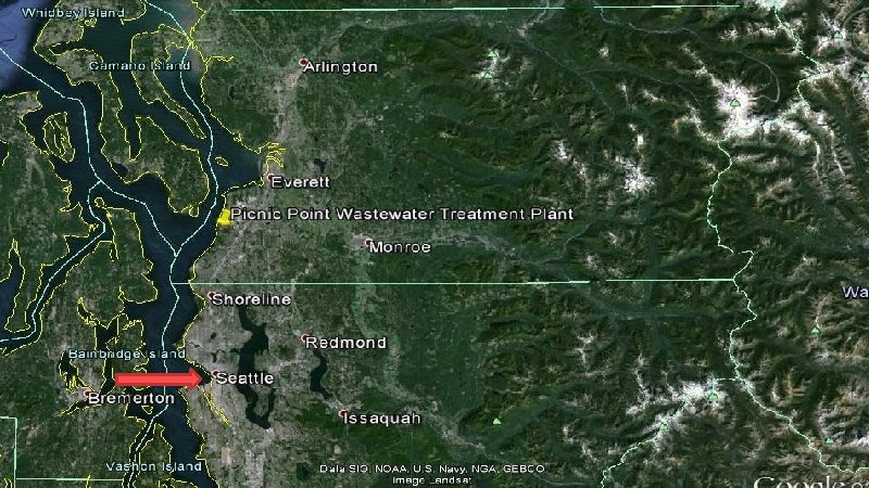
ALDERWOOD WATER AND WASTEWATER DISTRICT OUTFALL UPGRADE Seattle


- Slides: 57
ALDERWOOD WATER AND WASTEWATER DISTRICT OUTFALL UPGRADE Seattle University Senior Design Team CEE 16. 7 Kristin Ramey, Isabella Schwartz, Abbie Lorensen, Larissa Grundell
Science and Engineering Project Center College of Science and Engineering Seattle University Faculty Advisor: Dr. Michael Marsolek Sponsor: Alderwood Water and Wastewater District
Acknowledgments Thank you!
Useful Terms Outfall: The pipe that conveys treated effluent from the wastewater treatment plant to the Puget Sound Diffuser: The last section of pipe that has openings to distribute effluent into the surrounding water body
1, 300 ft - 18” Reinforced Concrete 80’ Diffuser 4” Portholes 3, 100 ft - 18” Ductile Iron 1972 – CAS Facility 2013 – MBR Facility
Project Motivation Structural Condition �Internal condition unknown �External inspections show signs of corrosion Pipe Capacity �Expanding Service Area Corrosion of pipe to flange weld at 12 o’clock position on outfall pipe.
Project Motivation Q= 8. 7 MGD Q=15. 8 MGD
Design Approach Preliminary Assessment �Condition Assessment �Hydraulic Analysis Design Selection Design Considerations �Detention Vault Design �Pipe Replacement �Mixing Zone Analysis Cost & Decision
Preliminary Assessment Condition Assessment Hydraulic Analysis
Preliminary Assessment Condition Assessment Hydraulic Analysis
Condition Assessment External Dive Inspection �Determine condition of submerged concrete pipe and diffuser �Results: Flanged end of diffuser in "poor" condition with heavy corrosion Indicates a new diffuser should be included in all design options Internal Camera Inspection �On hold
Preliminary Assessment Condition Assessment Hydraulic Analysis
Hydraulic Modeling Purpose: �Determine capacity of the outfall Approach: �Use PCSWMM to model dynamic outfall hydraulics Storm Water Management Model Constructed by the EPA �Use as-built information to construct model �Input weather flow data from December 2015 �Apply peaking factor
Hydraulic Modeling Conduit Junction
Hydraulic Modeling
Hydraulic Modeling Max Flow = 11. 1 MGD
Hand Calculations WWTP Z=169’ Z
Hand Calculations Velocity Head Ambient /Effluent Density Difference
Hand Calculations Datum
Hand Calculations
Hand Calculations
Hand Calculations Bend 1 2 3 4 5 6 7 8 Total Radius of Curvature 48 37. 3 7. 26 7. 16 3. 87 16. 26 14. 67 K 0. 35 0. 25 0. 16 0. 35 0. 32 1. 48’ 1. 48’ 0. 52’ 0. 37’ 0. 24’ 0. 52’ 0. 47’ 3. 48’
Hand Calculations
Hand Calculations
Hand Calculations WWTP Z
Capacity Conclusions Hydraulic modeling capacity = 11. 1 MGD Hand calculations capacity = 11 MGD �Corroborates modeling results 11 MGD capacity is less than the projected 15. 8 MGD �Design options need to account for flow attenuation
Design Selection Option 1 Option 2 Option 3 Partial Replacement Detention Vault Shallow Diffuser Extend Diffuser Full Replacement Extend Diffuser
Design Considerations Detention Vault Pipe Replacement Mixing Zone Analysis
Detention Vault Design Purpose: �Flow attenuation is required Approach: �Conservation of mass �Inflow – modified wet weather time series �Outflow – 10 MGD (conservative) Q=15. 8 Q=10 MGD 30, 000 gallons
Detention Vault Design Constrained by �Max Plan Dimensions: 100 ft X 45 ft �Pipe diameter of surrounding pipe network: 24 in Design Plan Dimensions: 45 ft X 15 ft Vault Detention Vault Plan View
Detention Vault Design Constrained by: �Allowable depth 22 ft. Design depth 10 ft Detention Vault Profile Section
Design Considerations Detention Vault Pipe Replacement Mixing Zone Analysis
Pipe Replacement Purpose: �Condition assessment shows concrete is deteriorating �Hydraulic analysis indicates insufficient capacity Approach: Partial Replacement Full Replacement Replace concrete portion with 24” pipe Replace entire system with 24” pipe Alleviate structural concerns Improves capacity Compatible with future upgrades Alleviate structural concerns
Pipe Replacement - Capacity Calculations WWTP Z
Pipe Replacement - Material Selection Ductile Iron Portion �Replace with 24” DIP Concrete Portion �Replace with 24” HDPE Advantages Corrosion resistance Fatigue Resistance Extended service life Flexibility Disadvantages Relies on surroundings for rigidity Floats Larger pipes require heavier/thicker walls Difficult to verify field joint quality
Pipe Replacement - Anchor Design: �Calculated Weight = 2120 lbs/Anchor Detail – Dimensions determined from weight requirement
Design Considerations Detention Vault Pipe Replacement Mixing Zone Analysis
Diffuser Design - Mixing Zone Analysis Purpose: �Scope of the project includes a diffuser design �Department of Ecology (DOE) requires a mixing zone analysis to receive an NPDES permit Approach: �Performed analysis on current diffuser �Used the same process for new diffuser design
Diffuser Design - Mixing Zone Analysis Steps 1. Determine mixing zone regions �Define acute and chronic zones boundaries as prescribed by the DOE Permit Writer’s Manual 2. 3. 4. Calculate dilution factors Calculate pollutant concentrations at mixing zone boundaries Ensure this meets pollutant regulations Wastefield plume Profile Section
Chronic Mixing Zone • 264. 4 Mixing ft. Acute Zone Aquatic • • 26. 4 ft. criteria considered • Aquatic criteria • considered Human health criteria considered for: • Carcinogenic pollutants • Non-carcinogenic pollutants Plan View
Diffuser Design - Dilution Calculations Input �Ambient water specifications current velocity and direction ambient water density �Discharge characteristics flow rates effluent density diffuser depth port size port spacing Visual Plumes will calculate the dilution ratio of the effluent to the water at specific distances from the diffuser
Diffuser Design - Pollutant Concentrations
Diffuser Design - Diffuser Selection Replaces open port diffuser with duckbill diffuser Duckbill valve remains closed under low flow preventing seawater intrusion and sediment buildup Duckbill Valve Profile View
Diffuser Design - Plume Depth Considerations To protect shellfish the plume boundary should be below -70 ft. MLLW -70 ft -115 ft
PROPOSED SYSTEM DESIGNS
Option 1 Replace with 24” HDPE
Option 2 Replace with 24” HDPE
Option 3 Upsize to 24”
Cost Estimate
Option Summary Option 1 Option 2 Option 3 Better Effluent Mixing Least Expensive Better Effluent Mixing Longest Potential Lifespan Most Expensive
Option Summary Option 1 Option 2 Option 3 Better Effluent Mixing Least Expensive Better Effluent Mixing Longest Potential Lifespan Most Expensive
Option Summary Option 1 Option 2 Option 3 Better Effluent Mixing Least Expensive Better Effluent Mixing Longest Potential Lifespan Most Expensive
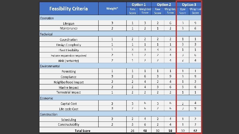
Conclusion Recommendation: Option 3 �Highest score in matrix Longest lifecycle Minimal O&M Minimal Impacts over lifespan AWWD Response �Incorporated Option 3 design into plant assessment project Option 3 Full Replaceme nt Extend Diffuser
QUESTIONS?
Diffuser Design - Dilution Calculations Average dilution Centerline dilution At 26. 4 ft. the DF is 45 Dilution with Acute Zone, Aquatic Life Criteria