WASTEWATER DISPOSAL WITH SUBSURFACE DRIP IRRIGATION Donald R

WASTEWATER DISPOSAL WITH SUBSURFACE DRIP IRRIGATION Donald R. Mc. Donald Ag. Tech Pacific

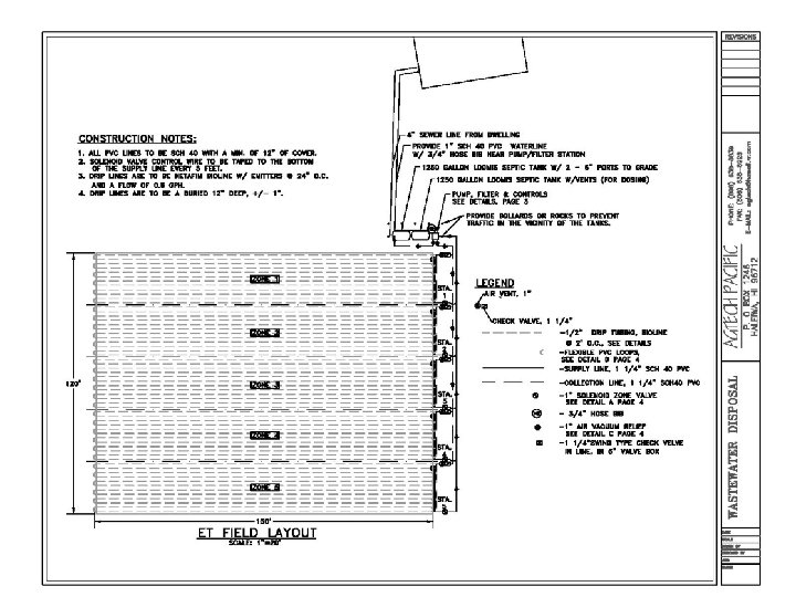
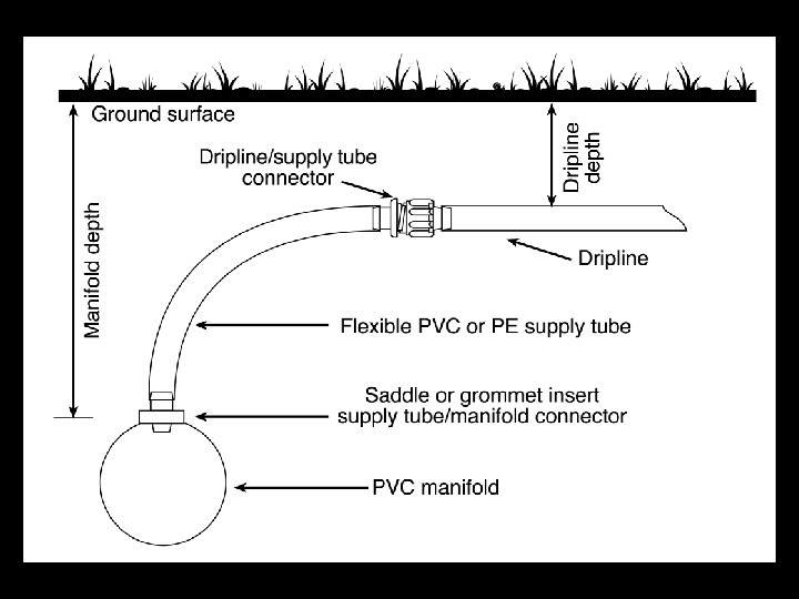
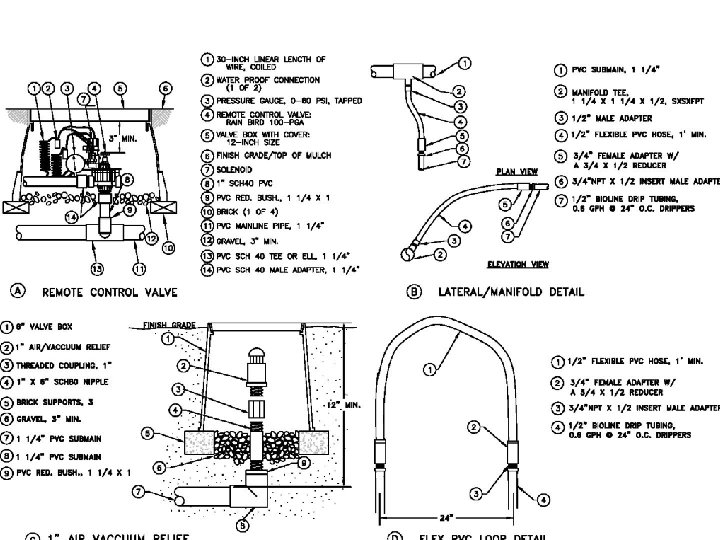
TYPICAL LAYOUT
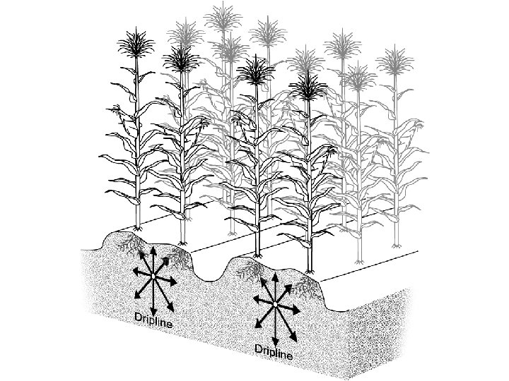

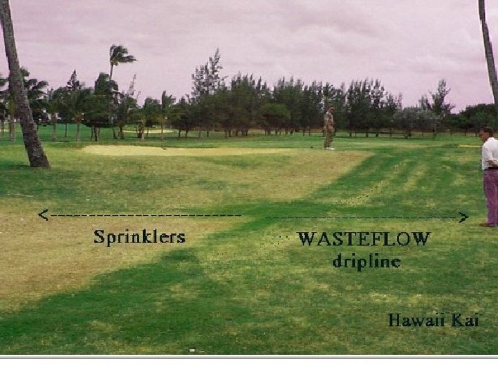
n Effluent is discharged through subsurface drip tubing often utilizing pressure compensating emission devices allowing effluent to be spread uniformly over an area.

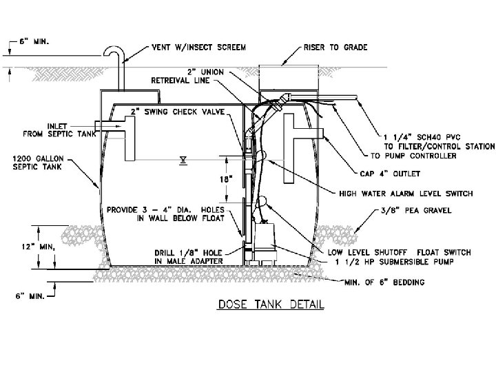
n Dosing cycles are triggered automatically several times per day with equal amounts of water supplied to each square foot. Dosing allows uniform distribution of effluent over time as well as area.

n Systems can be controlled by a programmed microprocessor or a simple irrigation controller.

n Any level of treatment from primary through tertiary can be handled by the system.

Advantages over a conventional IWS. n n Can be used where a high water table will not allow use of a conventional IWS. Or in area with excessively tight soils.

How it works n General Description

TYPICAL LAYOUT

Control Options. Computer Control interfaced with a pulsing water meter and telephone interface. n Simple Irrigation Controller with a manual read water meter. n

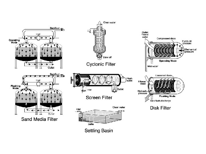
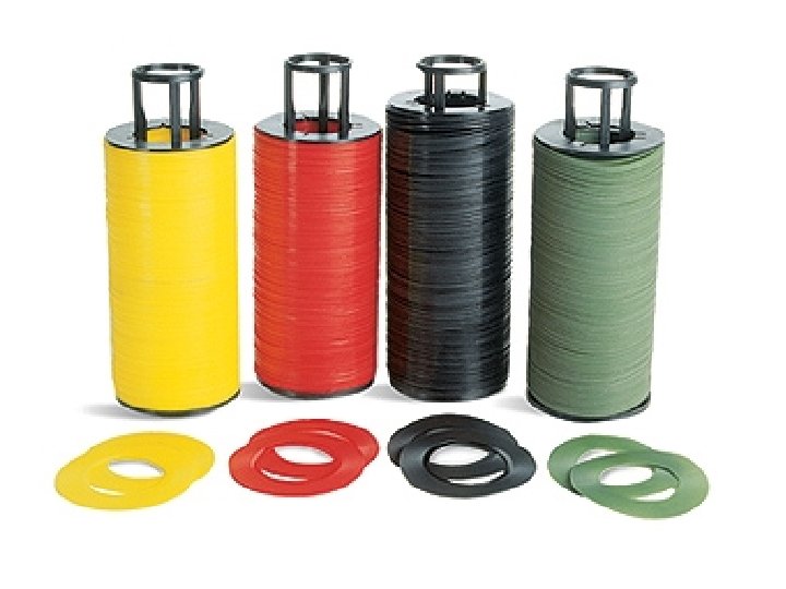
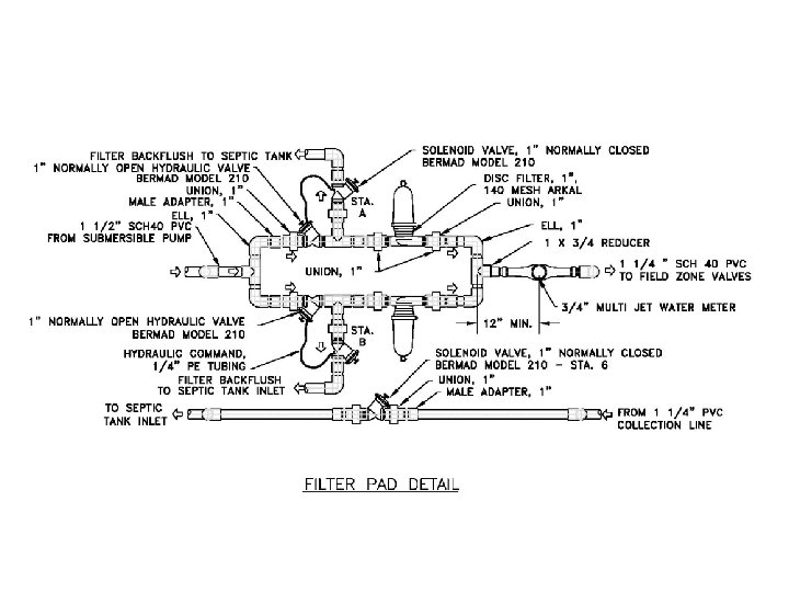
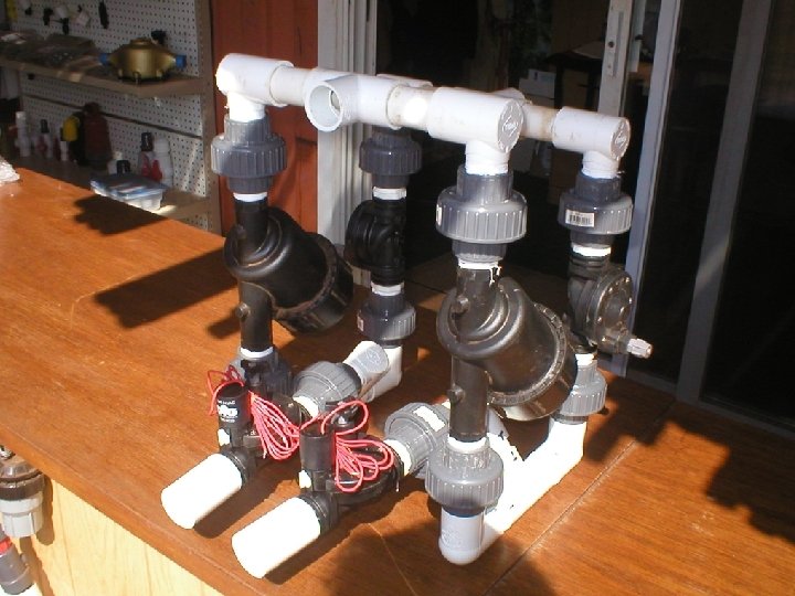
Self Cleaning Filtration Disc Filters n Screen Filters n Sand Media Filters n

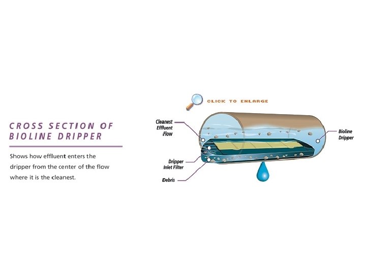
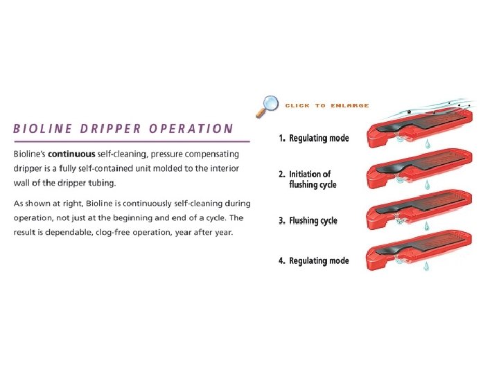
Drip Tubing - Two products currently used successfully n n Netafim Bioline – Pressure compensating Geoflow – Non pressure compensating with Rootguard

Design Considerations Design Flow – local regulations for IWS n Soil Loading Rate – Soil texture, refer to chart for general guidelines n

Application Guidelies for the Waste Water Systems Perc-Rite System Soil Group Soil Texture Classes (USDA Classification) Maximum Hydraulic Loading (gal/day/ft 2) I Sands (with S or PS structure) Sands –S Loamy Sand - LS 0. 4 - 0. 3 II Course Loams (with S or PS structure) Sandy Loam –SL Loam - L 0. 30 - 0. 15 III Fine Loams (with S or PS structure) Sandy Clay Loam – SCL Silt Loam – SIL Clay Loam – CL Silty Clay Loam - SICL IV Clays (with S or PS structure) Sandy Clay – SC Silty Clay – SIC Clay - C 0. 15 -. 10 0. 10 - 0. 03

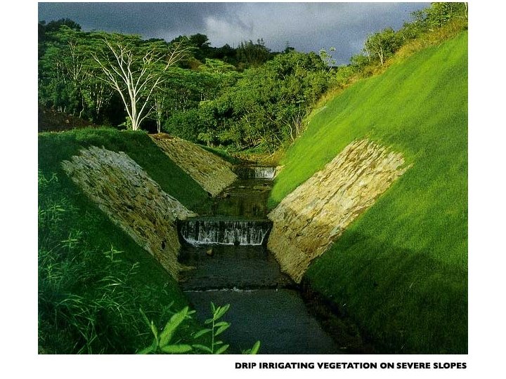
Additional Considerations Topography n Soil Compaction n Low areas where ponding might occur n Restrictive Layers n Setbacks required n

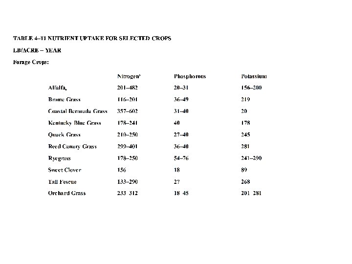
Additional Considerations n Nutrient load – more of a concern with Reuse
 –")
Design Steps n n n Determine Design flow in gallons per day (GPD) – refer to local regulations Determine Soil Loading Rate (GPD/square foot) Determine area required = Design Flow/Soil Loading Rate

Design Steps – n n continued Determine dripper spacing, i. e. : 2 feet Determine tubing spacing, i. e. : 2 feet Determine amount of tubing required = area required / tubing spacing Determine total flow rate based on tubing requirements

Design Steps – continued Determine Field Layout n Maximize lateral length to Minimize flush flow n Feed and collect from upper elevations where possible n

Design Steps – n n continued Determine Flush Flow required – 1. 6 GPM X the number of distal ends Break field into equal zones Calculate head losses and elevation changes Determine Pump Size

REFERENCES n n Netafim – www. netafim-usa. com Geoflow – www. geoflow. com Waste Water Systems – www. wastewatersystems. com American Manufacturing – www. americanonsite. com

The End
- Slides: 37