3 D Graphics Processor Architecture Victor Moya Ph

- Slides: 47
3 D Graphics Processor Architecture Victor Moya
Ph. D Project n Research on architecture improvements for future Graphic Processor Units (GPUs). n Design and implement a GPU simulator for 3 D graphics. n Goal: n Real-Time radiosity on GPU.
Outline n Rendering. n Global Illumination. n Ray Tracing. n Radiosity. n Status.
Outline n Rendering. n Global Illumination. n Ray Tracing. n Radiosity. n Status.
Rendering n Display a database of 3 D objects over a screen, a picture (file) or a movie (file). n Rendering methods for 3 D graphics: Rasterization. n Reyes. n Raytracing. n Radiosity. n
Rasterization Project 3 D polygons into a view plane. n Rasterize those polygons into fragments. n Shade the generated fragments. n n n Objective: n n Apply and combine textures to calculate the fragment color. Real-time. Make it look as realistic as possible. Avoid simulation of physical light behavior. With the help of vertex and fragment shaders can render realistic images.
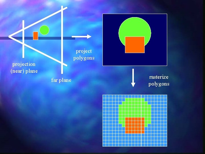
project polygons projection (near) plane far plane rasterize polygons
Reyes or Renderman is a rendering architecture designed for realistic offline rendering. n The 3 D objects are reduced to a number of micropolygons. n n Micropolygon: polygon smaller than a pixel. The micropolygons are then shaded and later sampled and written to the framebuffer. n Can be combined with raytracing, radiosity or other global illumination techniques. n
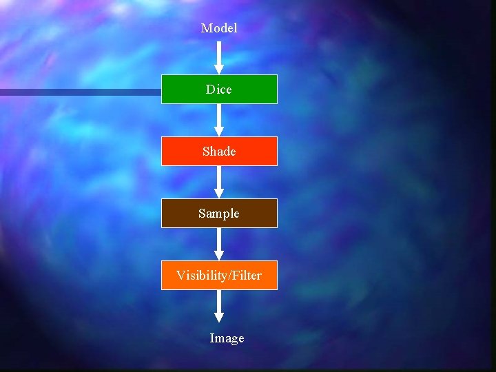
Model Dice Shade Sample Visibility/Filter Image
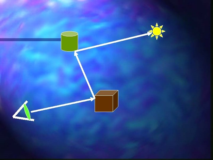
Ray. Tracing n n Project a ray from the camera (framebuffer) to the objects in the scene. Secondary rays may be created as reflections and refractions of the primary rays or other secondary rays. Rays may be sent from the light sources to create caustic light effects. Good simulation of reflection and transparency (refractions).
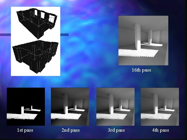
Radiosity Simulates the physical behavior of the light. n Define the emission, reflection, refraction, absorption and scattering properties of the scene surfaces. n n Mathematical formulation: system of linear equations. Build iteratively an approximation to the illumination solution. n Used to implement global illumination n Diffuse lightning. Indirect lightning.
16 th pass 1 st pass 2 nd pass 3 rd pass 4 th pass
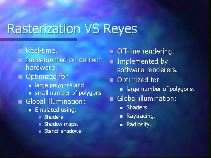
Rasterization VS Reyes Real-time. n Implemented on current hardware. n Optimized for n n large polygons and small number of polygons Global illumination: n Emulated using: n n n Shaders Shadow maps. Stencil shadows. Off-line rendering. n Implemented by software renderers. n Optimized for n n n large number of polygons. Global illumination: n n n Shaders. Raytracing. Radiosity.
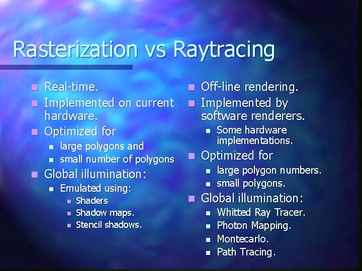
Rasterization vs Raytracing Real-time. n Implemented on current hardware. n Optimized for n n large polygons and small number of polygons Off-line rendering. n Implemented by software renderers. n n n Global illumination: n Emulated using: n n n Shaders Shadow maps. Stencil shadows. Optimized for n n n Some hardware implementations. large polygon numbers. small polygons. Global illumination: n n Whitted Ray Tracer. Photon Mapping. Montecarlo. Path Tracing.
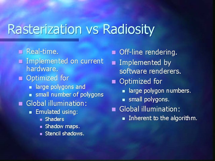
Rasterization vs Radiosity Real-time. n Implemented on current hardware. n Optimized for n n large polygons and small number of polygons Global illumination: n Emulated using: n n n Shaders Shadow maps. Stencil shadows. Off-line rendering. n Implemented by software renderers. n Optimized for n n large polygon numbers. small polygons. Global illumination: n Inherent to the algorithm.
Outline n Rendering. n Global Illumination. n Ray Tracing. n Radiosity. n Status.
Global Illumination and lightning depends on all the objects and lights in the scene. n BRDF: n n n Function that defines how light is reflected or refracted over a surface. Soft shadows: n Umbra and penumbra effects. Physically real reflections and refractions. n Indirect illumination: n n n Color blending. Caustics.
Why Global Illumination n Realism. n Single algorithm for the full the illumination problem: Direct illumination. n Indirect illumination. n Shadows. n
Global Illumination vs Real-Time Full scene global illumination algorithms are expensive. n Introduce illumination algorithm lod (level of detail). n n Not all scenes may require a full global illumination implementation. Not all parts of the scene may require a full global illumination implemention. Combine normal rasterization algorithms and techniques and global illumination techniques. n Reyes architecture.
Outline n Rendering. n Global Illumination. n Raytracing. n Radiosity. n Status.
Raytracing n Highly parallel task. n Raytracing algorithms: Raycasting. n Shadow Casting. n Whitted raytracing. n Photon mapping. n Montecarlo. n Path tracing. n
Rays n Types: Eye rays. n Shadow rays. n Reflected rays. n Refracted rays. n n Raytracing recursion depth. Static. n Adaptative. n
Raytracing on Current GPUs n Limitations: n n n Integer arithmetic and addressing not supported in current shader models. No generalized output buffers for fragment shader programs. No branching, looping or funtion calls. No stream buffer or conditional stream support. Under utilization of the vertex shader (1 quad per pass). n Vertex shader represent ~30% of the computing resources in current GPUs.
Outline n Rendering. n Global Illumination. n Raytracing. n Radiosity. n Status.
Radiosity n Light energy per unit surface leaving any surface in the scene. n Highly parallel. n Scene is divided in patches. n Form factor. n Fraction of light that reaches a surface i from a surface j.
Radiosity n Radiosity implementations: n Light maps and volumes. n n n Cube maps and Spherical Harmonics. n n Fast implementation on current hardware. Photon Mapping. n n Statically (off line) radiosity. Used with rasterization as textures. Implemented using raytracing. System of linear equations. n n Matrix resolution or approximation. Iterative resolution.
Photon Mapping on Current GPUs n Limitations: No integer ALU and addressing modes. n No support for large 1 D texture addressing (CPU loads). n No scatter capability at the shaders (CPU stores). n
Outline n Rendering. n Global Illumination. n Ray Tracing. n Radiosity. n Status.
Research Topics n Evaluate radiosity on Atila. n Propose software and hardware changes to make radiosity real-time.
Immediate changes n Unifiy shader model. n n Single shader model for vertex and fragment shaders. Generalize shader model. n n n Integer operations. Branches and function calls. Looping. Memory load (different from texture load). Texture write and memory store (scatter).
New architecture proposals n Reconfigurable shader architecture. n Streaming. n Deferred rendering. n Embedded DRAM. n Virtualization.
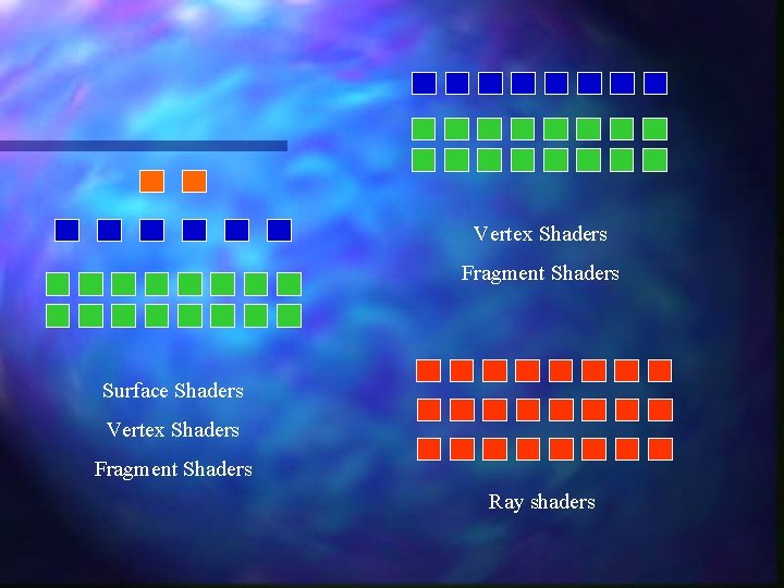
Reconfigurable Architecture n Static: n Variable rendering configuration for each algorithm: 2: 6: 16. n 0: 8: 16. n 0: 0: 24. n n Dynamic. Work balancing. n Streaming between shader units. n
Vertex Shaders Fragment Shaders Surface Shaders Vertex Shaders Fragment Shaders Ray shaders
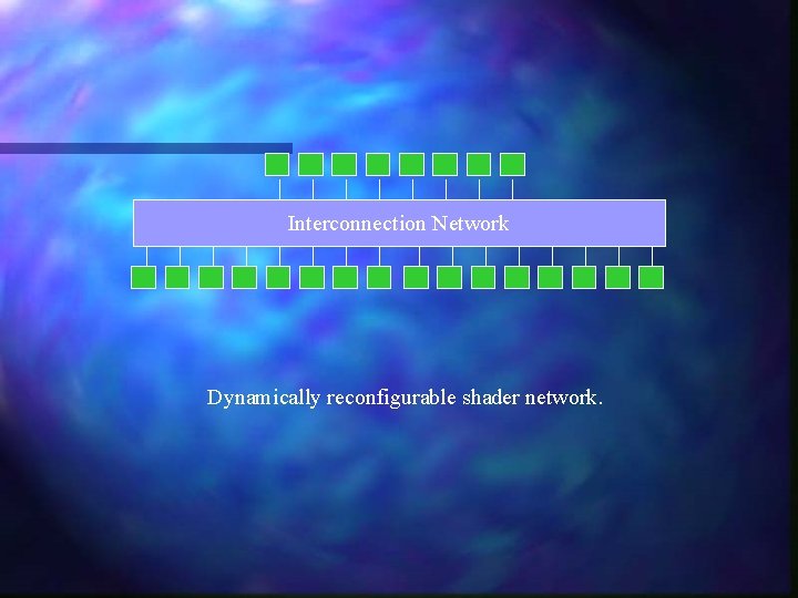
Interconnection Network Dynamically reconfigurable shader network.
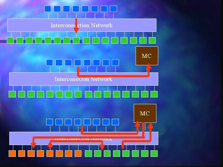
Streaming n Streaming on-chip buffers between shader units. n Conditional streams. n Any shader can: Stream in from memory. n Stream out to memory. n Stream in from another shader. n Stream out to another shader. n
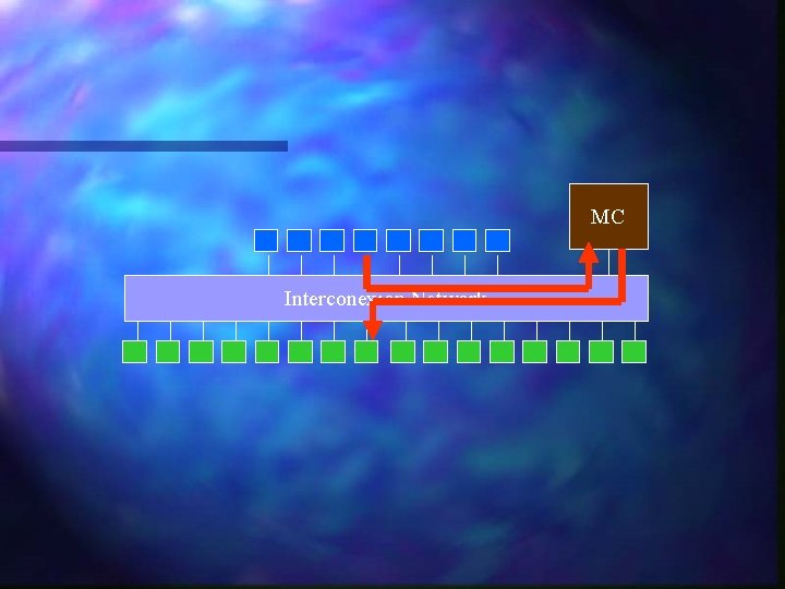
Interconnection Network MC Interconexion Network
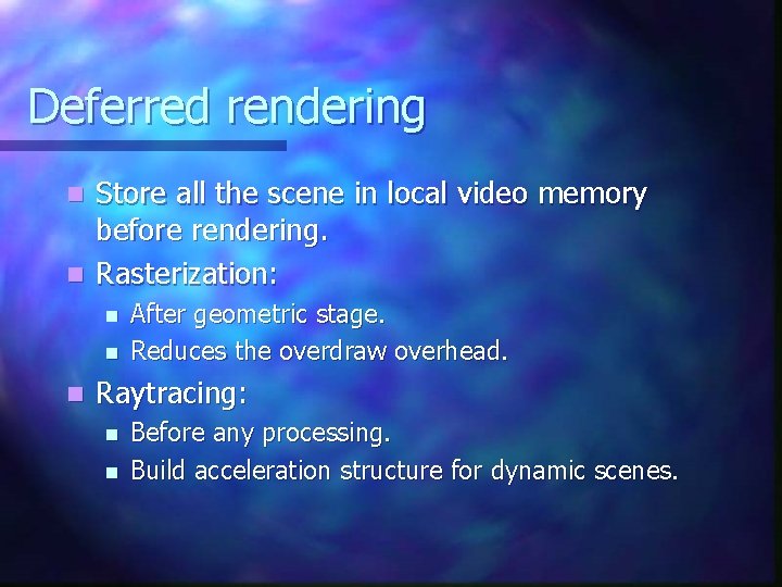
Deferred rendering Store all the scene in local video memory before rendering. n Rasterization: n n After geometric stage. Reduces the overdraw overhead. Raytracing: n n Before any processing. Build acceleration structure for dynamic scenes.
MC Interconexion Network
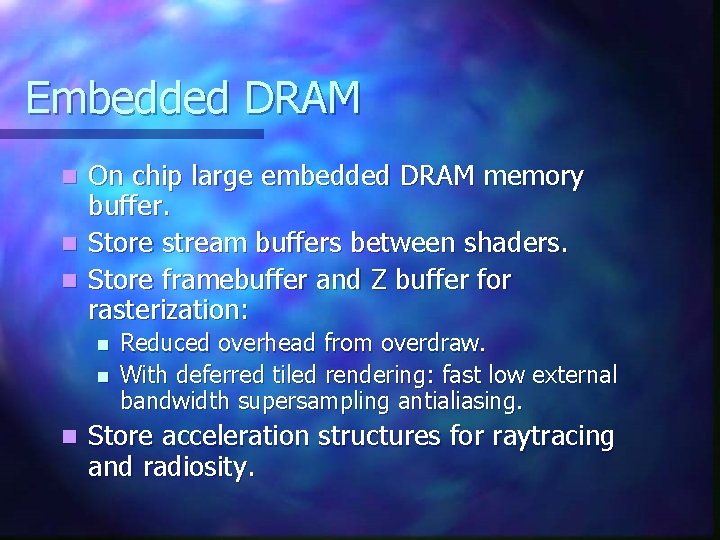
Embedded DRAM On chip large embedded DRAM memory buffer. n Store stream buffers between shaders. n Store framebuffer and Z buffer for rasterization: n n Reduced overhead from overdraw. With deferred tiled rendering: fast low external bandwidth supersampling antialiasing. Store acceleration structures for raytracing and radiosity.
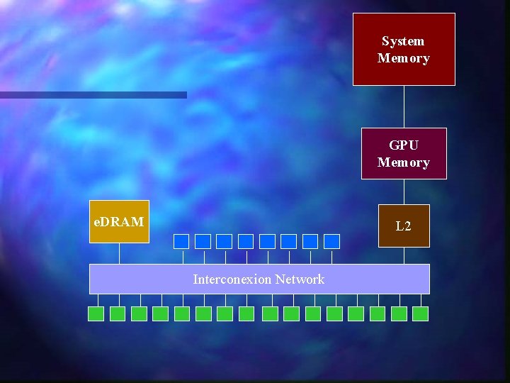
System Memory GPU Memory e. DRAM L 2 Interconexion Network
Virtualization n Virtualize GPU resources: Number of shader processors. n Size of on-chip stream buffers. n n Virtualize shader resources: Scratch RAM for register spills. n Instruction cache rather than intruction memory for unlimited program length. n
Virtualization n Virtualize n GPU memory: Memory hierarchy: On chip caches (L 1 or L 2). n On chip embedded DRAM buffers. n GPU video memory (L 2 or L 3). n System memory. n Disk. n
Specific vs Programable n Rasterization specific purpose hardware: Hierarchical Z Buffer. n Z and Stencil Buffer. n Rasterizer: n Triangle Setup. n Fragment Generation. n Interpolation. n
Specific vs Programable Future GPUs may replace specific purpose units with programable units (shaders). n Example: n n n Triangle Setup using homogenous coordinates setup algorithm [Olano & Greer] can be efficiently implemented by current shaders. Only use specific purpose units for those tasks that are more efficient using specific hardware.
Specific purpose hardware n Acceleration hardware for ray-triangle intersection. n Acceleration hardware for scene traversal. n Acceleration hardware for photon maps.
General Purpose GPUs A generalized GPU can be used as a highly parallel coprocessor for highly parallizable computation tasks. n Simulations: n n n Collision. Fluid simulation. FFT. n Matrix resolution. n Grid computing. n