Photonic Integrated Circuits LASERS AND LEDS ASSOC PROFESSOR


 beam propagates through an area light intensity")


,")

 • It can")


 • G is proportional to Rstim-Rabs • Can be computed or")


: κλ/2=L, κ=1, 2. . • From")


 Laser • Multiple longitudinal mode (MLM) spectrum • “Classic” semiconductor laser First")


 Laser- Σύνοψη • Single longitudinal mode (SLM) spectrum • High performance")
")
Σύνοψη • • Distributed Bragg Reflector (DBR) Mirrors •")


 Οι φορείς είναι τα ιόντα Ερβίου Η άντληση γίνεται")

 • Praseodymium-doped Fiber Amplifier (PDFA) • • • Similar to")


- Slides: 80
Photonic Integrated Circuits LASERS AND LEDS ASSOC. PROFESSOR C. MESARITAKIS DEPARTMENT OF INFORMATICS & TELECOMMUNICATIONS
Content Introduction • Basic mechanisms of lasing • Types of Lasers • Semiconductor Lasers Population Inversion and underlying effects • P-I • Rate equations • Mode Locking • • Types of Semicinductor Lasers DFB-DBR • External cavity • VCSELs • • Applications … 2
Basic Electron-Photon Mechanisms 3
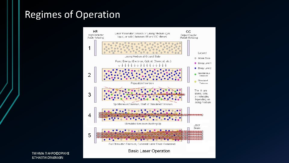
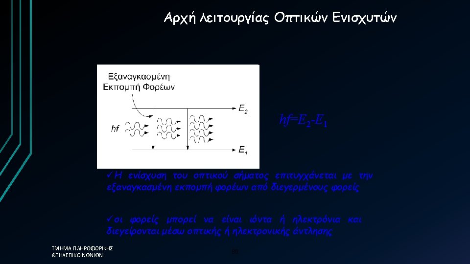
Optical Transitions • If radiation with f > Eg/h is injected then absorption mechanism becomes dominant. • If population inversion occurs spontaneous emission becomes dominant • If an optical cavity is in place, optical feedback will give rise to a chain reaction of photons, allowing stimulated emission to become dominant. • Light Amplification by Stimulated Εmission of Radiation ΤΜΗΜΑ ΠΛΗΡΟΦΟΡΙΚΗΣ &ΤΗΛΕΠΙΚΟΙΝΩΝΙΩΝ 4
Optical Absorption • If single wavelength (ideal) beam propagates through an area light intensity is provided by a are the losses per m Ι=Ι 0 exp(-ax) • Rate of photon loss per volume and for a propagation of dx: • Ι = ρ c 0/n (n o δ. δ. του μέσου) so: 5
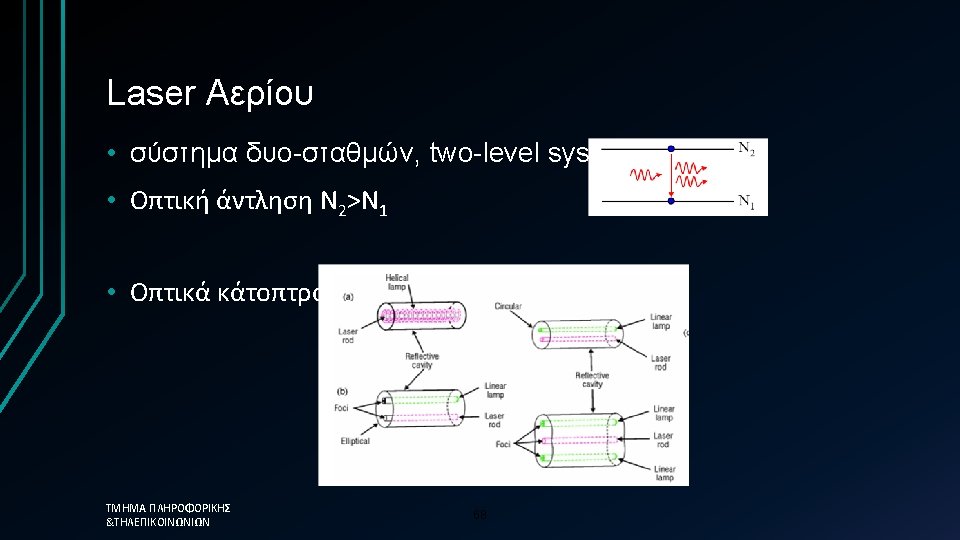
Population Inversion • If Ν 2>Ν 1 occurs by supplying energy to the optical system, then intensity increases Ι=Ι 0 exp(κx) με κ=-α>0 • Nonethless in a two level system maximum is Ν 1=Ν 2(transpartency • Therefore in order to achieve lasing a 3 -4 atomic system is required ΤΜΗΜΑ ΠΛΗΡΟΦΟΡΙΚΗΣ &ΤΗΛΕΠΙΚΟΙΝΩΝΙΩΝ 6
Optical Transitions in Semiconductors Remember the difference in the wavefunction for gases and solids!!!! 7
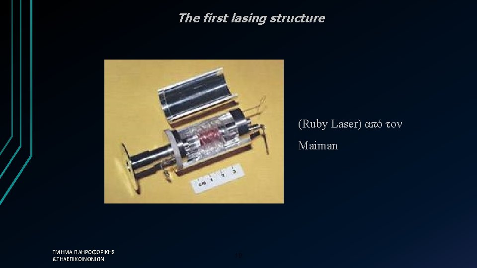
Key Events in Lasing 1916 ο Einstein explains stimulated emission 1958 οι Shawlow και Townes provide the fundamental principles of lasing 1960 o Maiman fabricates the first laser 1961 laser He-Ne (Α. Javan, W. Bennet, D. Harriott) 1962 diode laser from R. Hall 1963 Demonstration of CO 2 laser from Patel 1970 UV molecule (H 2) laser from R. Hodgson 1985 X-Ray laser from D. Mathews 1986 Ti: Sapphire laser from. Moulton 1994 Capasso developed the first quantum cascade laser 1996 VIS-blue laserαπό Ga. N (Nakamura) ΤΜΗΜΑ ΠΛΗΡΟΦΟΡΙΚΗΣ &ΤΗΛΕΠΙΚΟΙΝΩΝΙΩΝ 9
Proof of Principle • A laser structure consists of: • Active medium (direct bandgap…), • Pumping source (population inversion) • An optical cavity that drives stimulated emission and acts as a frequency selection mechanism ΤΜΗΜΑ ΠΛΗΡΟΦΟΡΙΚΗΣ &ΤΗΛΕΠΙΚΟΙΝΩΝΙΩΝ 11
Active Medium q. Atomic systems: laser He-Ne, He-Cd. q. Molecular systems: COB 2 B, Ar. F και Kr. F, NB 2 laser q Liquids: dye laser q Dielectric: Nd. YAG αλλά και στο σύστημα Nd: glass. q. Semiconductors: alloys of ΙΙΙ-V Ga, As, In, P 13
Pumping • Room temperature can not cause population inversion (fermi level!) • It can be easily achived if we forward bias a simple PN junction, allowing the accumulation of electrons at the conduction band • The excited electrons recombine with holes at the valance band allowing the generation of photons 16
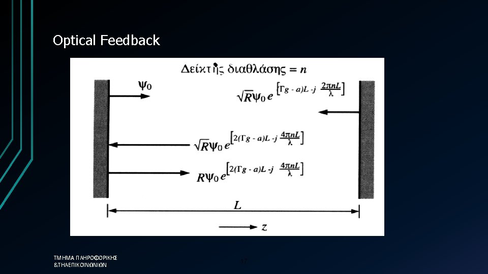
Optica Feedback Τελικά μετά από κ ανακλάσεις: κ: number of roundtrips Γ: confinement factor (~0. 4) g: gain of the material α: losses (absorption, scattering, mirrors) 2πLn/λ : single pass phase n: refractive index R: Reflectivity 18
Optical Feedback • Optical power increases with pumping • Coherent nature of the effect allows the increase of power with the power of two of each contribution • One of the two mirrors should be semi-transparent • Gain should match losses • Superposition creates maxima longitudinal modes • Με απόσταση: ΤΜΗΜΑ ΠΛΗΡΟΦΟΡΙΚΗΣ &ΤΗΛΕΠΙΚΟΙΝΩΝΙΩΝ 19
Lasing Threshold • Lasing is achieved after multiple passes, when: • As pumping increases, more free carriers accumulate in the valance band, thus reducing the refractive index This reduces the distance between the longitutional modes • In general: ΤΜΗΜΑ ΠΛΗΡΟΦΟΡΙΚΗΣ &ΤΗΛΕΠΙΚΟΙΝΩΝΙΩΝ 20
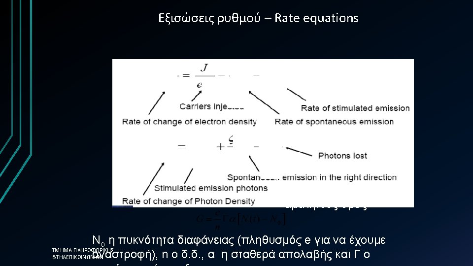
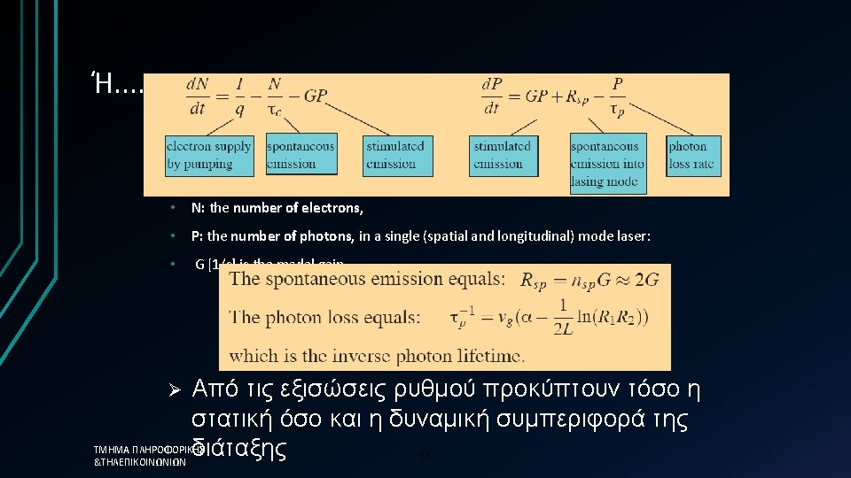
Optical Gain (G) • G is proportional to Rstim-Rabs • Can be computed or estimated through experiemnts • Depends on carrier density Ν and Gmax ισχύει: • gp(N)=σg(N-Nτ) 21
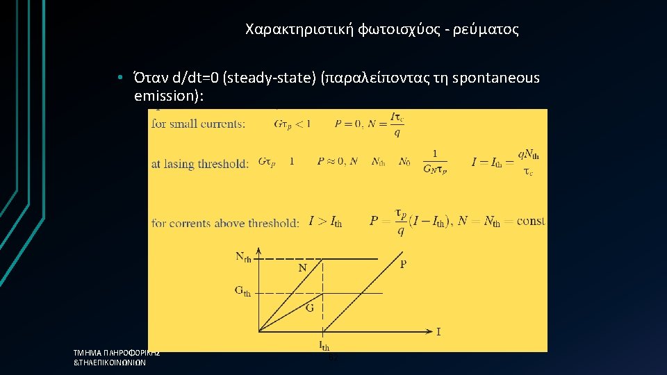
P-I curve • Linewidth reduction • side-mode suppression • Central wavelength moves towards lower wavelengths • the slope is the external quantum efficiency (what is the internal? ) ΤΜΗΜΑ ΠΛΗΡΟΦΟΡΙΚΗΣ &ΤΗΛΕΠΙΚΟΙΝΩΝΙΩΝ 22
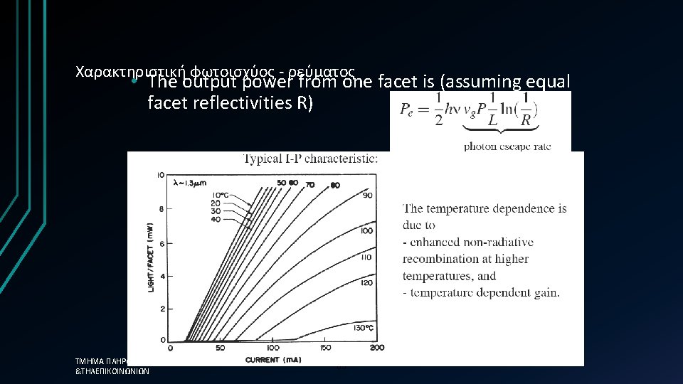
Temperature dependence Long-wavelength emitting diodes are more sensitive to temperature variations ? ? ?
Noise in Laser • Phase Noise: the most dominant cause for non-zero linewidth. It is caused due to the existence of spontaneous emission that allows the generation of photons with random phase. • Relative Intensity Noise – RIN: it is a type of signal-to-noise ratio that is defined as the amplitude of variations at the output versus the mean output power (d. B/Hz) • Typical RIN are: • FP -125 εώς -130 d. B/Hz • Laser DFB έχει τιμές κάτω από -155 d. B/Hz … why is it smaller? ? ? • example: if a laser has RIN= -130 d. B/Hz and the overall bandwidth is 1 MHz then the SNR will be 70 d. B. ΤΜΗΜΑ ΠΛΗΡΟΦΟΡΙΚΗΣ &ΤΗΛΕΠΙΚΟΙΝΩΝΙΩΝ 24
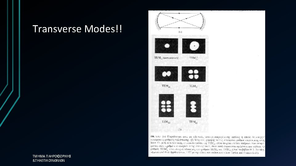
Longitudinal Modes Defined by the cavity (refractive index-length): κλ/2=L, κ=1, 2. . • From the spectral response of gain. G=G(ν) • For each integer κ a single mode is defined! • 25
Basic Properties of Laser Structure • • • Directionality: θ=λ/D Linewidth δλ Coherence length Brightness (power/m 2) Number of modes Central emission Quantum Efficiency (external) Power consumption – thermal Noise properties 31
Typical Semiconductor Laser • Typical PN diode • Forward Biasing • III-V materials direct energy bandgap • Electrical pumping • Heterostructure (optical guiding) • QW-Qwires-QDs ΤΜΗΜΑ ΠΛΗΡΟΦΟΡΙΚΗΣ &ΤΗΛΕΠΙΚΟΙΝΩΝΙΩΝ 34
Hetrojunction as Lasers …. 35
Fabry-Perot (FP) Laser • Multiple longitudinal mode (MLM) spectrum • “Classic” semiconductor laser First fiberoptic links (850 or 1300 nm) • Today: short & medium range links P peak • • Key characteristics • • Most common for 850 or 1310 nm Total power up to a few mw Spectral width 3 to 20 nm Mode spacing 0. 7 to 2 nm Highly polarized Coherence length 1 to 100 mm Small NA ( good coupling into fiber) ΤΜΗΜΑ ΠΛΗΡΟΦΟΡΙΚΗΣ &ΤΗΛΕΠΙΚΟΙΝΩΝΙΩΝ P Threshold I 40
Optical Filters … a recap • Portion of the light is reflected at each interface • Only for one wavelength can a coherent addition be performed • Wavelength satisfying the Bragg Condition, λB: 2Λneff=λB • neff is the effective index of the waveguide core • Very narrow bandwidths are possible • To force single-mode lasing one introduces a wavelength dependent cavity loss ΤΜΗΜΑ ΠΛΗΡΟΦΟΡΙΚΗΣ &ΤΗΛΕΠΙΚΟΙΝΩΝΙΩΝ 42
Laser DBR • Active region is terminated by a Bragg Reflector • Can use either a single ended grating or have a grating on both ends. • Can be made tunable ΤΜΗΜΑ ΠΛΗΡΟΦΟΡΙΚΗΣ &ΤΗΛΕΠΙΚΟΙΝΩΝΙΩΝ 44
DFB Lasers Bragg grating placed in the vicinity of the active region • Feedback takes place throughout the laser cavity • Bragg condition must satisfied • Narrow linewidth operation • Wavelength tuning is possible by heating the grating • Most communication lasers are DFB lasers ΤΜΗΜΑ ΠΛΗΡΟΦΟΡΙΚΗΣ &ΤΗΛΕΠΙΚΟΙΝΩΝΙΩΝ Grating period 240 -245 nm!! • Wavelength = 2 neff 45
Distributed Feedback (DFB) Laser- Σύνοψη • Single longitudinal mode (SLM) spectrum • High performance telecommunication laser Most expensive (difficult to manufacture) • Long-haul links & DWDM systems • • Key characteristics • • • ΤΜΗΜΑ ΠΛΗΡΟΦΟΡΙΚΗΣ &ΤΗΛΕΠΙΚΟΙΝΩΝΙΩΝ P peak Mostly around 1550 nm Total power 3 to 50 mw Spectral width 10 to 100 MHz (0. 08 to 0. 8 pm) Sidemode suppression ratio (SMSR): > 50 d. B Coherence length 1 to 100 m Small NA ( good coupling into fiber) 46 SMSR
VCELS • Συγκεντρώνουν τον optical mode σε περιοχή διαμέτρου 3μm (Μονότροπη - εγκάρσια λειτουργία) VCSEL: Vertical Cavity Surface Emitting Laser. • • ΤΜΗΜΑ ΠΛΗΡΟΦΟΡΙΚΗΣ • &ΤΗΛΕΠΙΚΟΙΝΩΝΙΩΝ Replaces the traditional edge emitting geometry with a surface emitter Gives a VERY short cavity length Widely spaced longditudinal modes – well outside the gain bandwidth. Single mode operation Current injected through a shaped contact Small size gives efficient operation and high switching speeds Circular output well matched to fibre. On-chip testing possible for cheap production. Still difficult to obtain long wavelength 49 operation, but rapidly becoming the most import laser source for datacomms applications.
Vertical Cavity Surface Emitting Lasers (VCSEL)Σύνοψη • • Distributed Bragg Reflector (DBR) Mirrors • Alternating layers of semiconductor material • 40 to 60 layers, each l / 4 thick • Beam matches optical acceptance needs of fibers more closely Key properties • Wavelength range 780 to 980 nm (gigabit ethernet) • Spectral width: <1 nm • Total power: >-10 d. Bm • threshold current < 1 -m. A. • Coherence length: 10 cm to 10 m • Numerical aperture: 0. 2 to 0. 3 p-DBR active n-DBR ΤΜΗΜΑ ΠΛΗΡΟΦΟΡΙΚΗΣ &ΤΗΛΕΠΙΚΟΙΝΩΝΙΩΝ 50
Long-wavelength VCSELs • For fiber optical communication purposes VCSELs emitting in the 1. 3 -1. 55 m region (long-wavelength) are used • It has been difficult to fabricate a monolithic semiconductor DBR for a longwavelength VCSEL. The main reason is that the difference in refractive indexes for the fabrication materials are very small, about half the difference of that used for shorter wavelength VCSEL. • There has been two approaches made to overcome this problem, the use of wafer-fused Ga. As/Al. As mirrors and the use of dielectric mirrors. Both approaches lead to very promising results • Βέβαια μέχρι σήμερα αξεπέραστο παραμένει το πρόβλημα της χαμηλής εκπεμπόμενης ισχύος ΤΜΗΜΑ ΠΛΗΡΟΦΟΡΙΚΗΣ &ΤΗΛΕΠΙΚΟΙΝΩΝΙΩΝ 52
Απλοποιημένη προσέγγιση üThe photon lifetime, τph, is the fundamental limit üτph=0. 12 ps →Modulation frequency = 8. 3 THz ΤΜΗΜΑ ΠΛΗΡΟΦΟΡΙΚΗΣ &ΤΗΛΕΠΙΚΟΙΝΩΝΙΩΝ üHowever in reality the 58 limit is much less than this
Amplifier Types and. Applications Amplifiers are used to overcome fiber loss They are used in 4 basic applications: In-line amplifiers for periodic power boosting: Power Amplifier to increase the power to greater levels than possible from the source: Pre-amplifier to increase the received power sensitivity: Distribution loss compensation in local area or cable networks: Fiber Optics Communication Technology-Mynbaev & Scheiner ΤΜΗΜΑ ΠΛΗΡΟΦΟΡΙΚΗΣ &ΤΗΛΕΠΙΚΟΙΝΩΝΙΩΝ 79
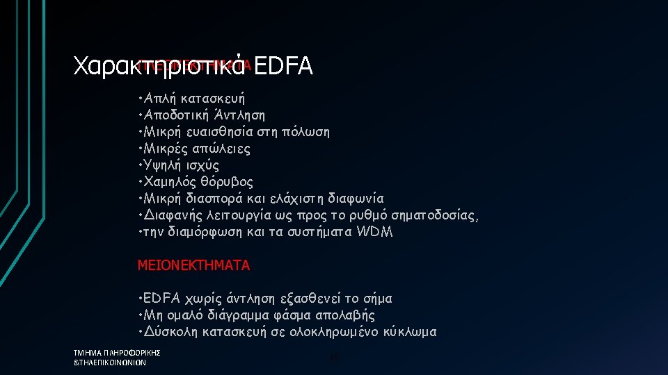
Τύποι οπτικών ενισχυτών Οι βασικοί τύποι οπτικών ενισχυτών είναι: üSemiconductor amplifiers SOA (lasers that aren’t lasing) üDoped fiber amplifiers EDFA üRaman and Brillouin Amplifiers Τα κυριώτερα χαρακτηριστικά παράμετροι: üGain and gain bandwidth üGain saturation üNoise and noise figure ΤΜΗΜΑ ΠΛΗΡΟΦΟΡΙΚΗΣ &ΤΗΛΕΠΙΚΟΙΝΩΝΙΩΝ 83
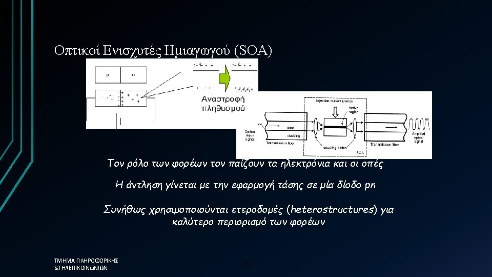
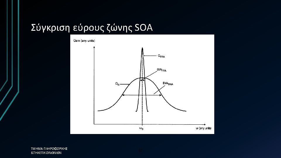
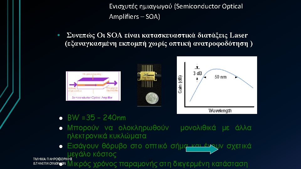
Τύποι Ενισχυτών ημιαγωγού – SOA Fabry-Perot Amplifier High gain G but non-uniform gain spectrum Traveling wave amplifier Broadband but very low facet reflectivities are needed G=G(f) Ripples are caused by the cavity modes The overall gain curve is due to the width of the atomic transition in the semi-conductor ΤΜΗΜΑ ΠΛΗΡΟΦΟΡΙΚΗΣ &ΤΗΛΕΠΙΚΟΙΝΩΝΙΩΝ 85
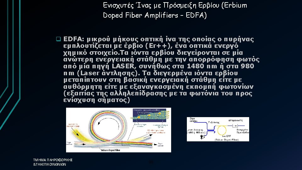
Οπτικοί Ενισχυτές Ίνας Ερβίου (EDFA) Οι φορείς είναι τα ιόντα Ερβίου Η άντληση γίνεται με LASER στα 980 nm ή στα 1480 nm. ü 980 nm pumping generates both higher gain and less noise ü 1480 nm pumping generates higher saturated power and tolerates a broader range of pump wavelengths ΤΜΗΜΑ ΠΛΗΡΟΦΟΡΙΚΗΣ &ΤΗΛΕΠΙΚΟΙΝΩΝΙΩΝ 91
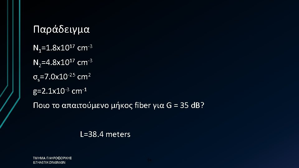
Απαιτούμενο μήκος Er-doped fiber q Gain coefficient per length g depends on population inversion and cross section for stimulated emission Overall gain G depends on g and length L: Και σε decibels: ΤΜΗΜΑ ΠΛΗΡΟΦΟΡΙΚΗΣ &ΤΗΛΕΠΙΚΟΙΝΩΝΙΩΝ 93
Praseodymium-doped Fiber Amplifier (PDFA) • Praseodymium-doped Fiber Amplifier (PDFA) • • • Similar to EDFAs but 1310 nm optical window Deployed in CATV (limited situations) Not cost efficient for 1310 telecomm applications Fluoride based fiber needed (water soluble) Much less efficient (1 W pump @ 1017 nm for 50 m. W output) ΤΜΗΜΑ ΠΛΗΡΟΦΟΡΙΚΗΣ &ΤΗΛΕΠΙΚΟΙΝΩΝΙΩΝ 96
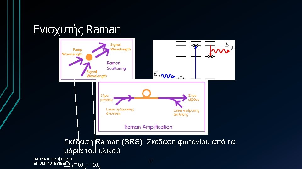
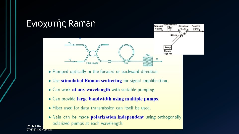
Δηλαδή. . . • Raman amplifiers: • Use stimulated Raman effect and pump laser whose frequency is equal to signal frequency plus frequency of chemical bond in the material • Because it is a nonlinear process, requires very high pump powers (watts) ΤΜΗΜΑ ΠΛΗΡΟΦΟΡΙΚΗΣ &ΤΗΛΕΠΙΚΟΙΝΩΝΙΩΝ 99
Power and noise outputs amplified power Power out: mt=number of transverse modes, Δ f=optical filter bandwidth, nspon=population inversion factor ΤΜΗΜΑ ΠΛΗΡΟΦΟΡΙΚΗΣ &ΤΗΛΕΠΙΚΟΙΝΩΝΙΩΝ 103 (ASE) noise