Network Programming Eddie Aronovich mail eddieamta ac il


 – Sockets –")


 4 Data transport layer protocol (Fragment packets to fit")
 Destination port number (16 bit) Length (16")


 Dest port number (16 bit) Sequence number")

; connect returns…. SYN j SYN k, ACK j+1 listen();")
; bind(); listen(); accept(); {New")
 Vs. Active close FIN M ACK M+1 FIN")


 4 Reading is done")

- Slides: 55
Network Programming Eddie Aronovich mail: eddiea@mta. ac. il
How did it started ?
How can we write communication ? 4 Application Program Interface (API) – Sockets – TLI (Transport Layer Interface) 4 System calls 4 Library functions
What is it for ? Communication systems provides 3 services: – Information & resource Sharing – Distance gapping – Backup abilities
Fundamentals 4 Server - An entity which gives services 4 Client - An entity which requests services 4 Transport layer - To transfer the data
The 7 layers model
The 7 Layer model in real life
The message is built in one side. . .
And striped in the dest. side…
From Lynx to Netscape or chat client Presentation
Descriptors 4 Everything in Unix is a file 4 Descriptor is an index into an array
Memory Buffers 4 Contains Socket Address Structure 4 Headers 4 Data
The Basics of communication Lecture. II
Processing Techniques
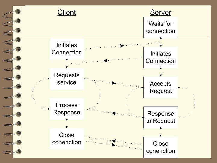
The Client Server Model 4 The server roles: – Give service as asked – Wait the client to appeal to him 4 The client roles: – Start the communication process – Asks the wanted service
Design considerations 4 Serve single or multiple users 4 Use reliable or unreliable protocol 4 Software updates
Client and server roles in UDP 4 Server roles: – Bind a port – Wait for a message to come – Send reply 4 Client roles: – Send a message – Get the reply
User Datagram Protocol* 4 Simple protocol 4 Connectionless 4 Unreliable }*RFC 768}
Socket: ={ip_addr, port number} 4 API, an interface for the program to contact with communication. 4 Enable usage of regular file commands as read, write and so on. 4 The sockets are structures passed from kernel to process and vice versa.
What the socket struct contains ? 4 Socket type {stream, dgram, raw, …} 4 Socket options {broadcast, OOB. . . } 4 Time to linger wait before close the socket 4 Socket state flags 4 Protocol Control Block 4 Protocol Handle
The socket & address structs 4 General struct sockaddr { uint 8_t sa_family_t char sa_len; sa_family; sa_data[20]; /*Len of socket struct */ /*Addr family as AF_INET */ /*Protocol Address */ 4 IP V 4 address socket struct sockaddr_in { uint 8_t */ sa_family_t addresses */ unit 16_t */ struct char sin_len; sin_family; sin_port; /*The socket length /*AF_INET for IP /*The port id 16 -bit port num in_addr sin_addr; /*The IP address 32 -bit sin_zero [8]; /* FFU - Must be zero */ */
How the socket is created 4 The system call passes identifiers for address family(e. g. AF_UNIX, AF_INET, etc. ), socket type and protocol. 4 Socket data structure is allocated. 4 Pointer from the fd table to other i-node struct which points to the socket.
User Datagram Protocol (rfc 768) 4 Data transport layer protocol (Fragment packets to fit local MTU) 4 Used to make available datagram packet switched mode 4 Connectionless protocol 4 Used when RTT is important or no connection needed
UDP header Source port number (16 bit) Destination port number (16 bit) Length (16 bit) UDP Checksum (16 bit) Data
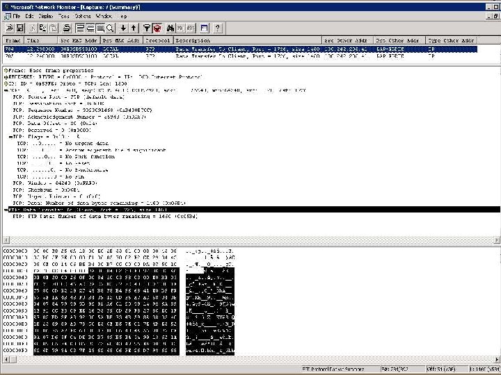
UDP by network monitor
Lets do it in UDP - client C: TEMPudp-cli-c. htm
Lets do it in UDP - server C: TEMPudp-srv-c. html
TCP Lecture. III
Transmission Control Protocol rfc 793 4 Reliability 4 Sequenced data transfer 4 Flow control 4 Full duplex
TCP Header Source port number (16 bit) Dest port number (16 bit) Sequence number (32 bit) Acknowledgement number (32 bit) FIN SYN RST PSH ACK F. F. U (6 bit) URG Header length (4 bit) TCP Checksum (16 bit) Window size (16 bit) Urgent Pointer (16 bit) Options Data
Ack & Flow control 4 Acknowledgements are sent by byte. 4 The acks can be sent for group of packets (but should arrive before time out of first packet). 4 Window size is used for flow control and is controlled by receiver.
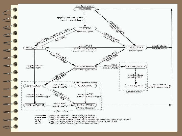
How connection starts ? connect(); connect returns…. SYN j SYN k, ACK j+1 listen(); accept returns…. ACK k+1 Connection Established
How we do it in C ? Server Client socket(); bind(); listen(); accept(); {New file descriptor is given} connect();
Ending Sessions Passive close (FIN arrives) Vs. Active close FIN M ACK M+1 FIN N ACK N+1
Internet Protocol Lecture. IV
Network Layer 4 Passing packet from source host to destination host (cross networks if needed) 4 Independent of the datalink layer 4 Qo. S 4 Flow control
Internet Protocol 4 Connectionless 4 Unreliable 4 Best effort
Address 4 IP address consist 32 bit and is divided into {network id. , host id} 4 Part of host id can be used for subnet mask 4 Some special addresses are defined (as: net- addr, broadcast-addr, multicast-addr)
Addresses and Classes Class A 01 XXXXXX Addresses: 0 -127. X. X. X Class B 10 XXXXXX Addresses: 128 -191. 0 -255. X. X Class C 110 XXXXX Addresses: 192 -223. 0 -255. X
Masks 4 Mask is used to refine network division. 4 ‘ 1’b in mask symbolize bit belongs to network address. 4 ‘ 0’b in mask symbolize bit belongs to host address.
Address conventions 4 Network address filled with ‘ 0’ in host address. 4 Broadcast address filled with ‘ 1’ in host address. 4 First, last subnet and address aren’t used
How routing is done ? 4 The router compares destination IP with each Network & subnet address. 4 Unknown destination is routed to default. 4 Routers update each other with appropriate algorithms.
VI שיעור I/O Multiplexing
I/O Models 4 Blocking I/O 4 Nonblocking I/O 4 I/O Multiplexing 4 Signal driven 4 Asynchronous I/O
Non-Blocking I/O 4 No blocking is done (Error is returned) 4 Reading is done in loop (until data arrives) 4 Polling – costs CPU time 4 Implementation in real time systems only
Signal Driven I/O 4 Signal handler should be started