Mountain Ridge Project final presentation The making of

- Slides: 46
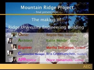
Mountain Ridge Project - final presentation - The making of Ridge University Engineering Building Owner Architect Regina Pau, Engineer Construction Manager APPrentice Martha Del. Campo, Sunnyvale Katrin Wender, Weimar Stanford Kris Grotelueschen, Grace Yamamoto, Stanford AEC
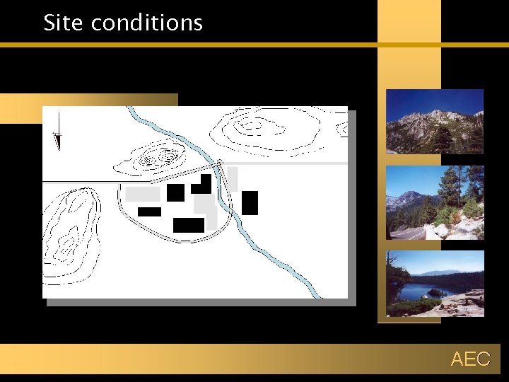
Site conditions AEC
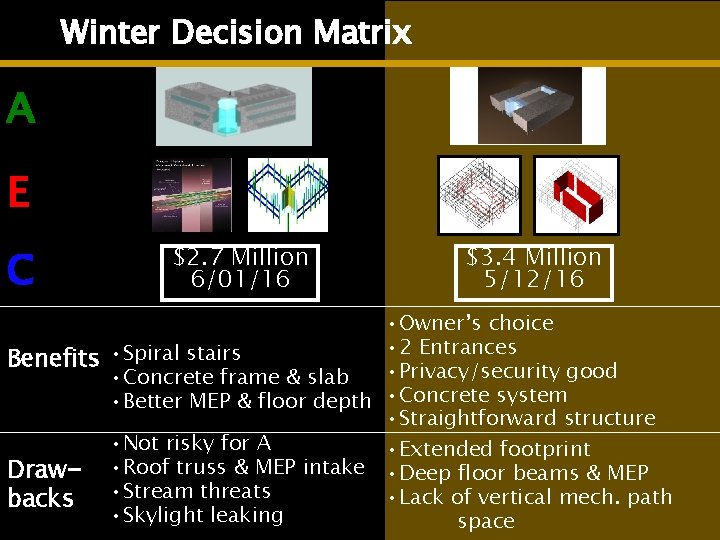
Winter Decision Matrix A E C $2. 7 Million 6/01/16 $3. 4 Million 5/12/16 • Owner’s choice • 2 Entrances Benefits • Spiral stairs • Privacy/security good • Concrete frame & slab • Better MEP & floor depth • Concrete system • Straightforward structure • Not risky for A • Extended footprint Draw- • Roof truss & MEP intake • Deep floor beams & MEP • Lack of vertical mech. path backs • Stream threats • Skylight leaking space
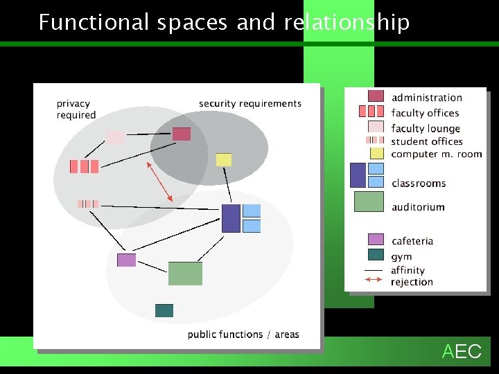
Functional spaces and relationship AEC
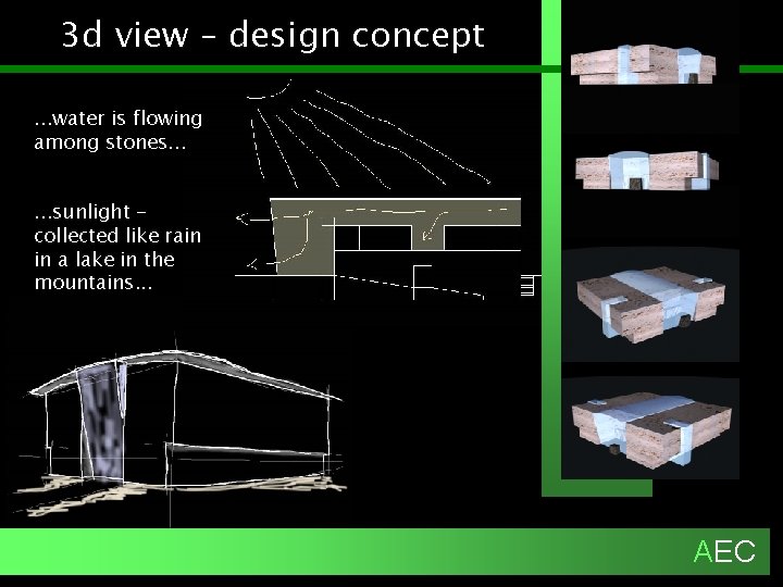
3 d view – design concept. . . water is flowing among stones. . . sunlight collected like rain in a lake in the mountains. . . AEC
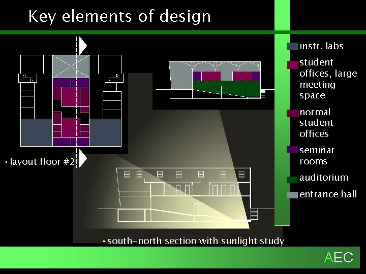
Key elements of design instr. labs student offices, large meeting space normal student offices seminar rooms • layout floor #2 auditorium entrance hall • south-north section with sunlight study AEC
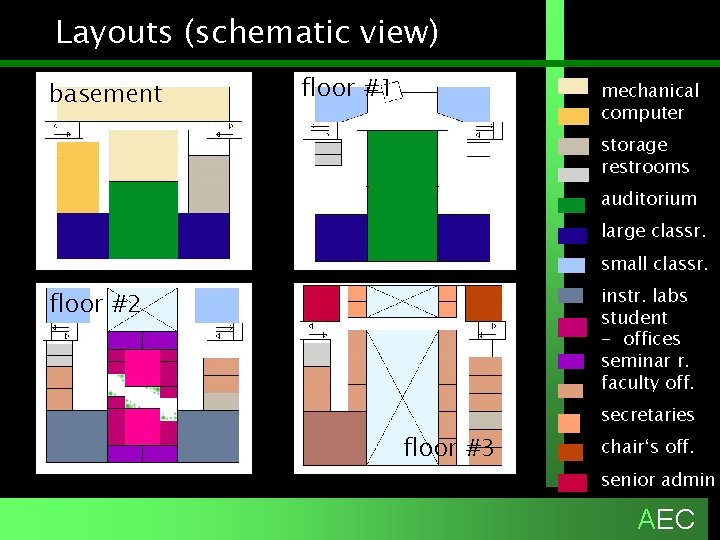
Layouts (schematic view) basement floor #1 mechanical computer storage restrooms auditorium large classr. small classr. instr. labs student - offices seminar r. faculty off. floor #2 secretaries floor #3 chair‘s off. senior admin AEC
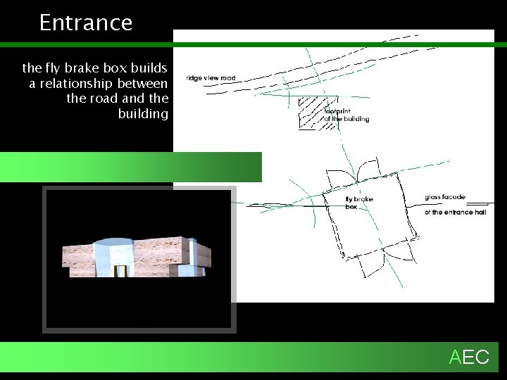
Entrance the fly brake box builds a relationship between the road and the building AEC
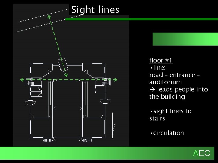
Sight lines floor #1 • line: road – entrance – auditorium leads people into the building • sight lines to stairs • circulation AEC
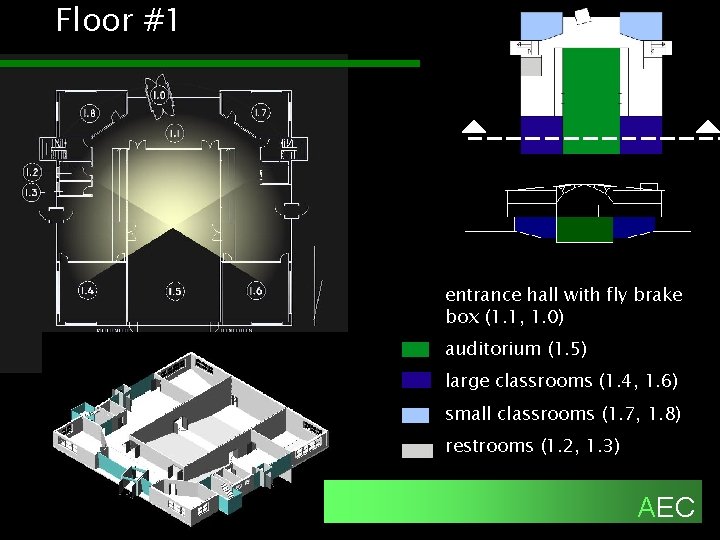
Floor #1 entrance hall with fly brake box (1. 1, 1. 0) auditorium (1. 5) large classrooms (1. 4, 1. 6) small classrooms (1. 7, 1. 8) restrooms (1. 2, 1. 3) AEC
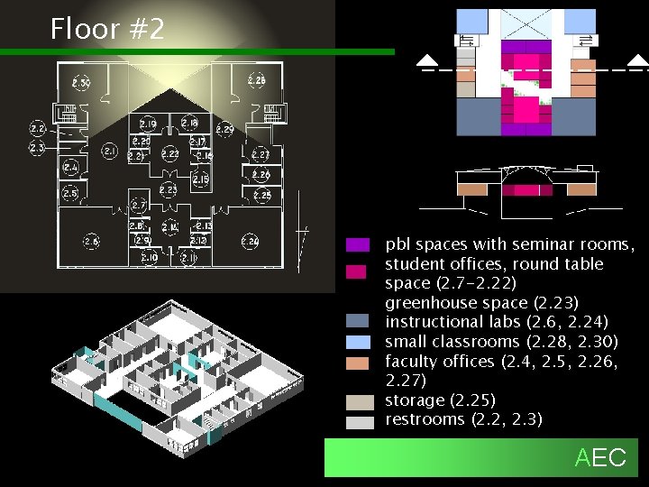
Floor #2 pbl spaces with seminar rooms, student offices, round table space (2. 7 -2. 22) greenhouse space (2. 23) instructional labs (2. 6, 2. 24) small classrooms (2. 28, 2. 30) faculty offices (2. 4, 2. 5, 2. 26, 2. 27) storage (2. 25) restrooms (2. 2, 2. 3) AEC
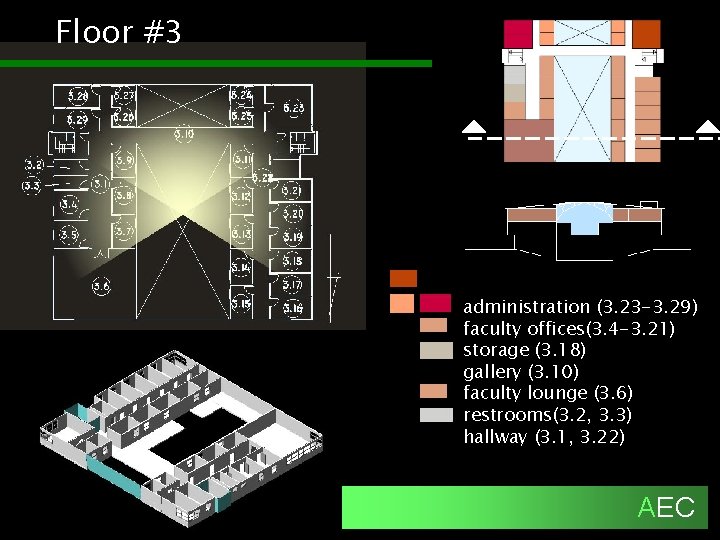
Floor #3 administration (3. 23 -3. 29) faculty offices(3. 4 -3. 21) storage (3. 18) gallery (3. 10) faculty lounge (3. 6) restrooms(3. 2, 3. 3) hallway (3. 1, 3. 22) AEC
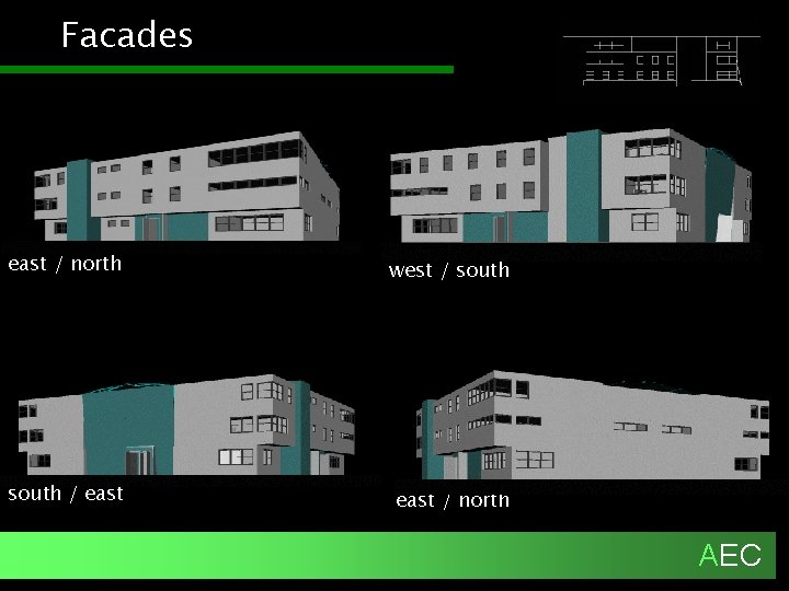
Facades east / north west / south / east / north AEC
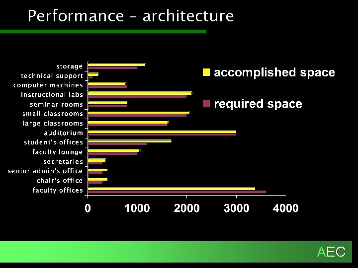
Performance – architecture AEC
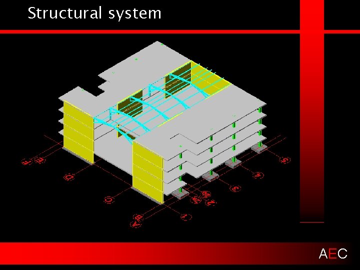
Structural system AEC
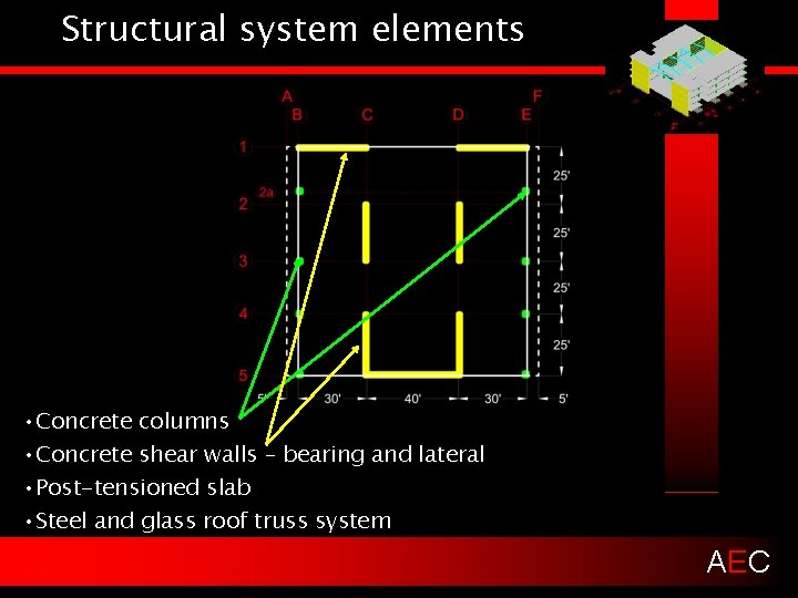
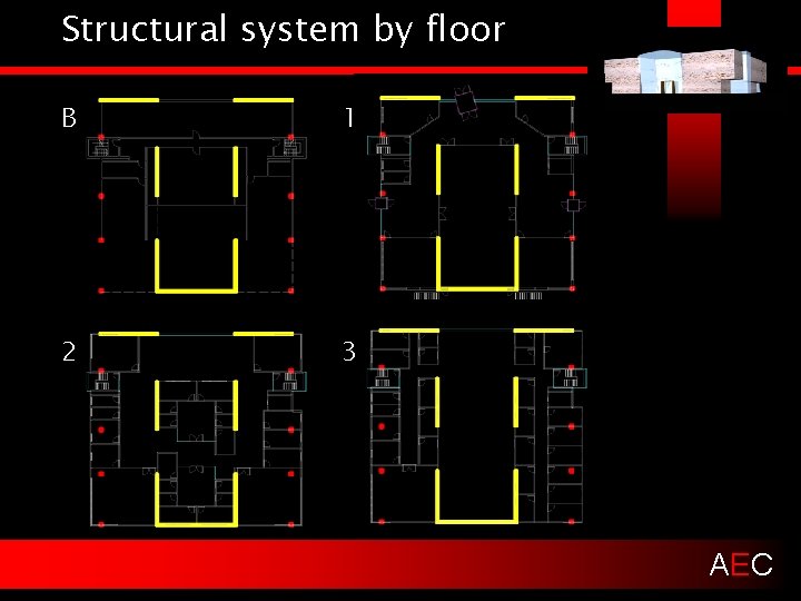
Structural system elements • Concrete columns • Concrete shear walls – bearing and lateral • Post-tensioned slab • Steel and glass roof truss system AEC
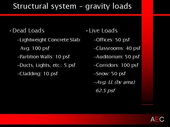
Structural system – gravity loads • Dead Loads –Lightweight Concrete Slab: Avg. 100 psf • Live Loads –Offices: 50 psf –Classrooms: 40 psf –Partition Walls: 10 psf –Auditorium: 50 psf –Ducts, Lights, etc. : 5 psf –Corridors: 100 psf –Cladding: 10 psf –Snow: 50 psf –Avg. LL (by area): 62. 5 psf AEC
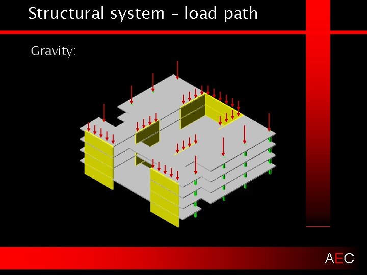
Structural system – load path Gravity: AEC
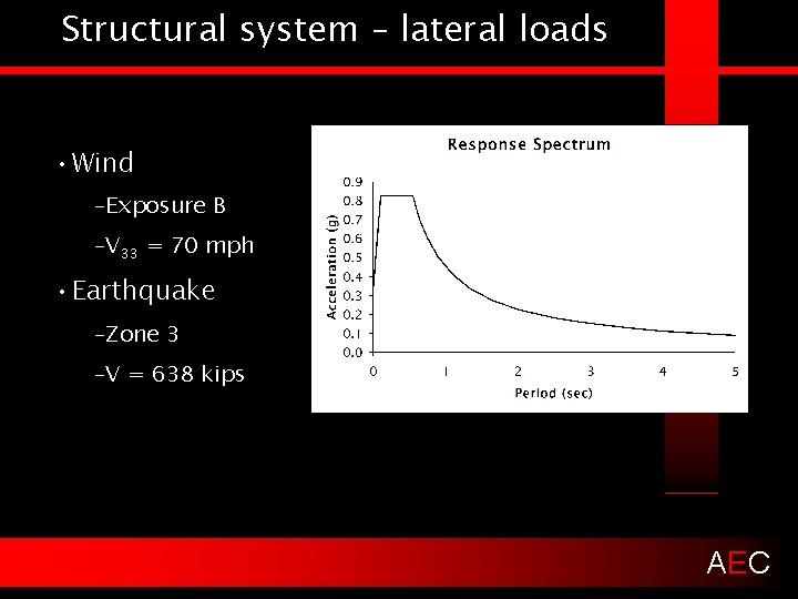
Structural system – lateral loads • Wind –Exposure B –V 33 = 70 mph • Earthquake –Zone 3 –V = 638 kips AEC
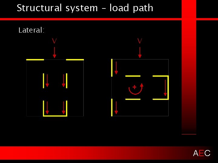
Structural system – load path Lateral: V V AEC
Structural system by floor B 1 2 3 AEC
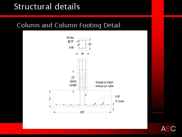
Structural details Column and Column Footing Detail: AEC
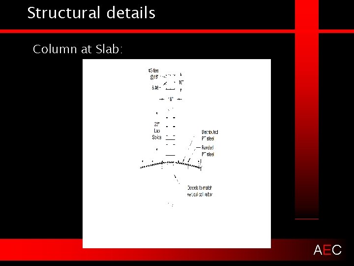
Structural details Column at Slab: AEC
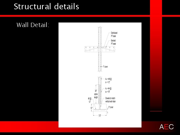
Structural details Wall Detail: AEC
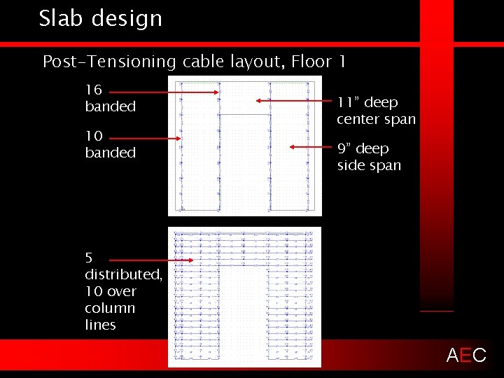
Slab design Post-Tensioning cable layout, Floor 1 16 banded 10 banded 11” deep center span 9” deep side span 5 distributed, 10 over column lines AEC
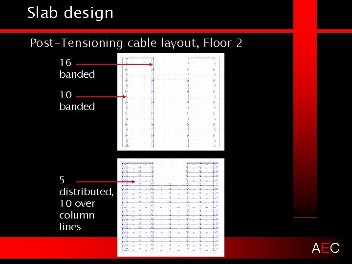
Slab design Post-Tensioning cable layout, Floor 2 16 banded 10 banded 5 distributed, 10 over column lines AEC
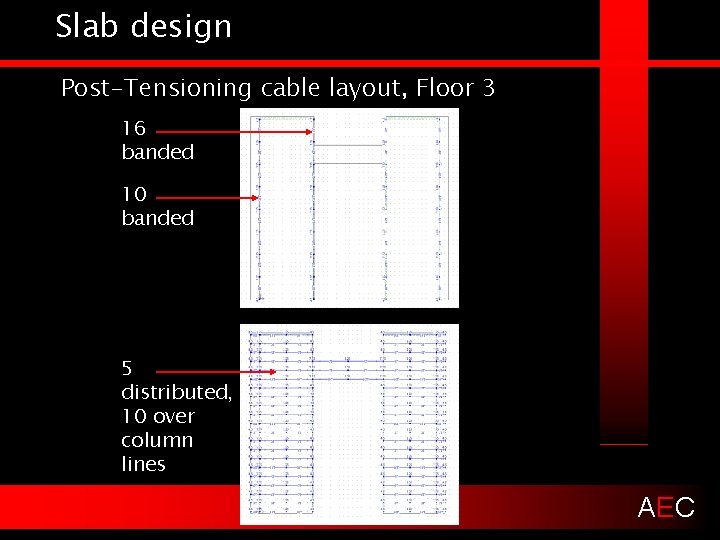
Slab design Post-Tensioning cable layout, Floor 3 16 banded 10 banded 5 distributed, 10 over column lines AEC
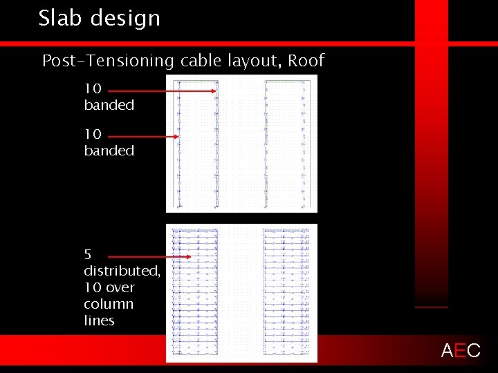
Slab design Post-Tensioning cable layout, Roof 10 banded 5 distributed, 10 over column lines AEC
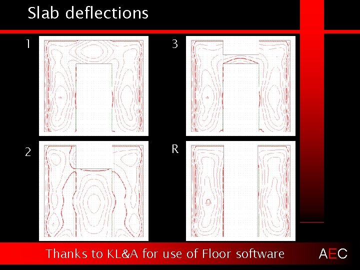
Slab deflections 1 3 2 R Thanks to KL&A for use of Floor software AEC
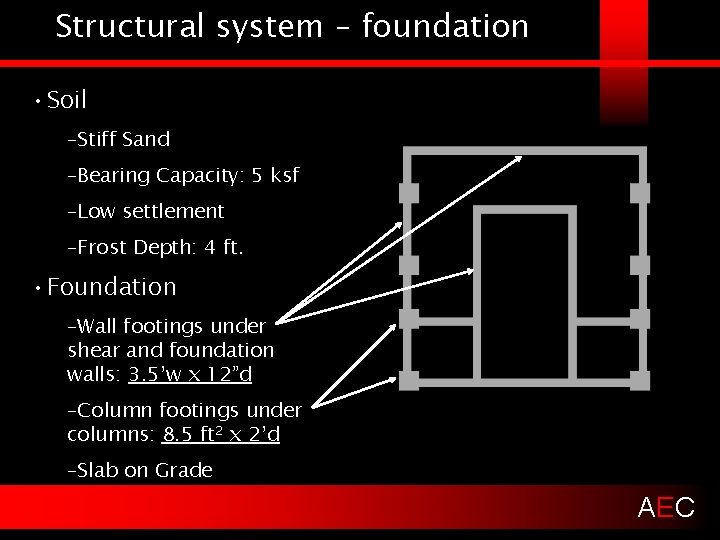
Structural system – foundation • Soil –Stiff Sand –Bearing Capacity: 5 ksf –Low settlement –Frost Depth: 4 ft. • Foundation –Wall footings under shear and foundation walls: 3. 5’w x 12”d –Column footings under columns: 8. 5 ft 2 x 2’d –Slab on Grade AEC
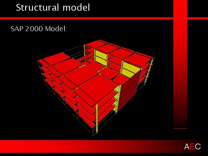
Structural model SAP 2000 Model: AEC
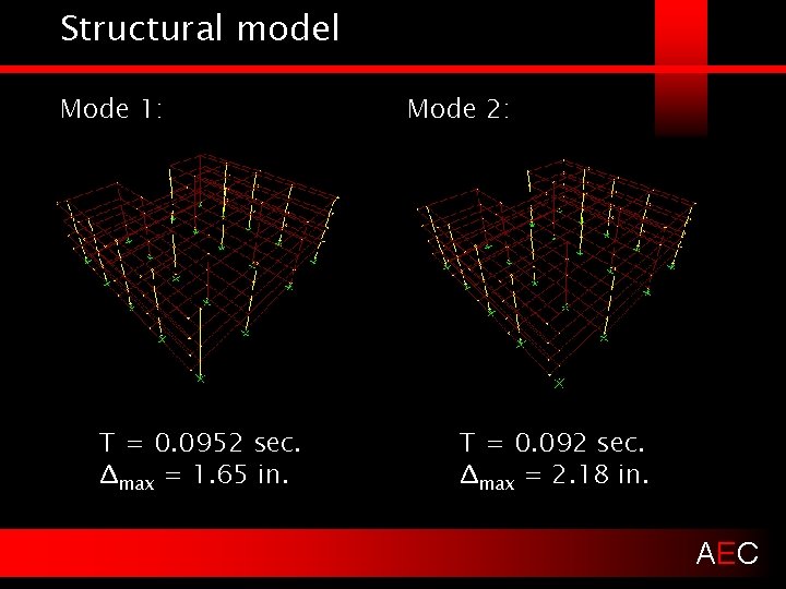
Structural model Mode 1: T = 0. 0952 sec. Δmax = 1. 65 in. Mode 2: T = 0. 092 sec. Δmax = 2. 18 in. AEC
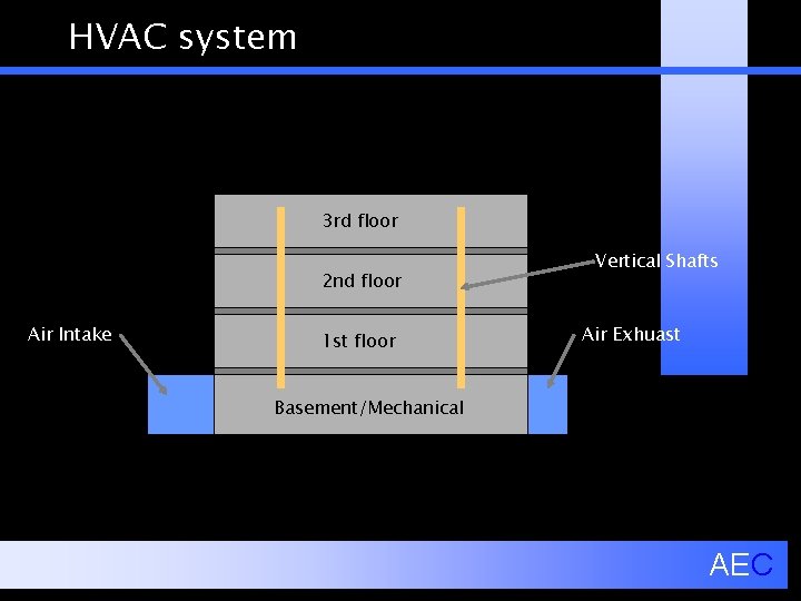
HVAC system 3 rd floor 2 nd floor Air Intake 1 st floor Vertical Shafts Air Exhuast Basement/Mechanical AEC
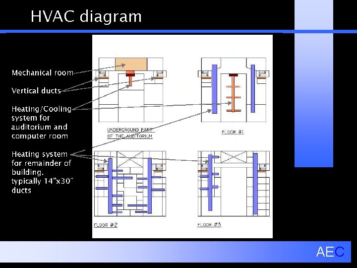
HVAC diagram AEC
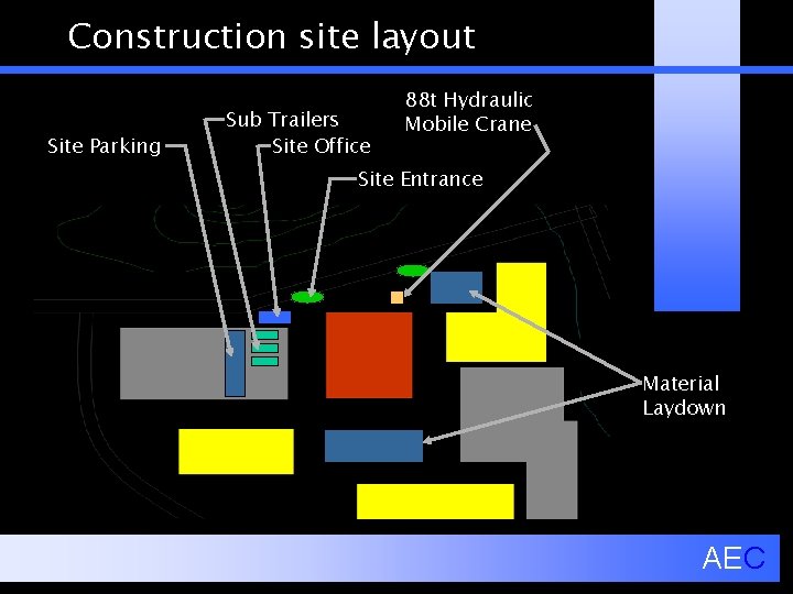
Construction site layout Site Parking Sub Trailers Site Office 88 t Hydraulic Mobile Crane Site Entrance Material Laydown AEC
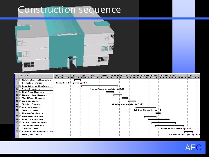
Construction sequence AEC
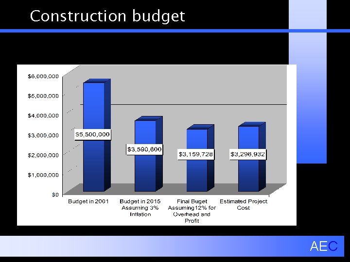
Construction budget AEC
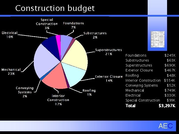
Construction budget Foundations $245 K Substructures $63 K Superstructures $690 K Exterior Closure $467 K Roofing $48 K Interior Construction $554 K Conveying Systems $52 K Mechanical $749 K Electrical $330 K Special Construction $99 K Total $3, 297 K AEC
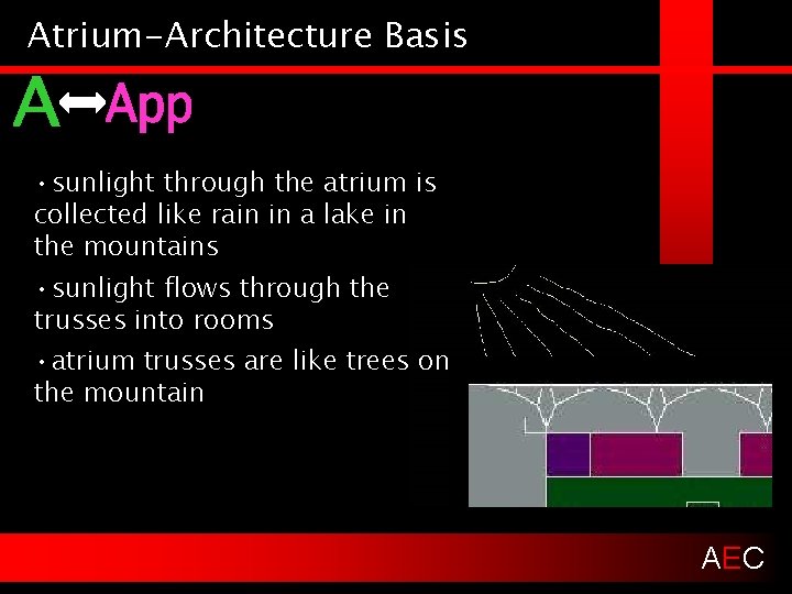
Atrium-Architecture Basis • sunlight through the atrium is collected like rain in a lake in the mountains • sunlight flows through the trusses into rooms • atrium trusses are like trees on the mountain AEC
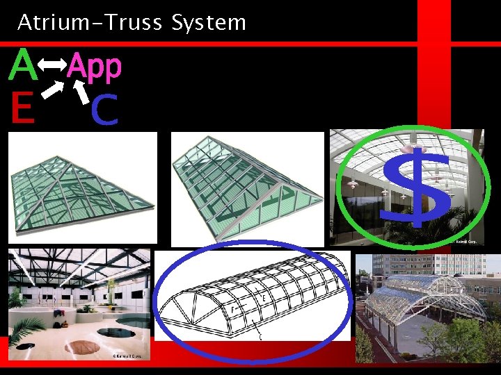
Atrium-Truss System AEC
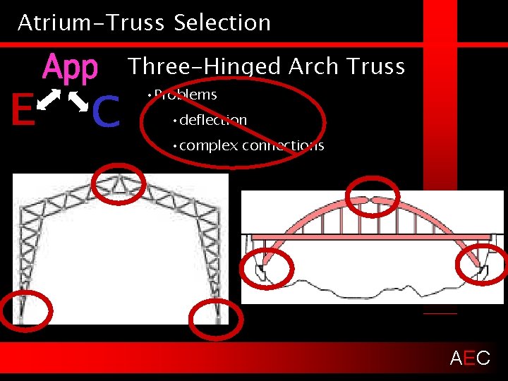
Atrium-Truss Selection Three-Hinged Arch Truss • Problems • deflection • complex connections AEC
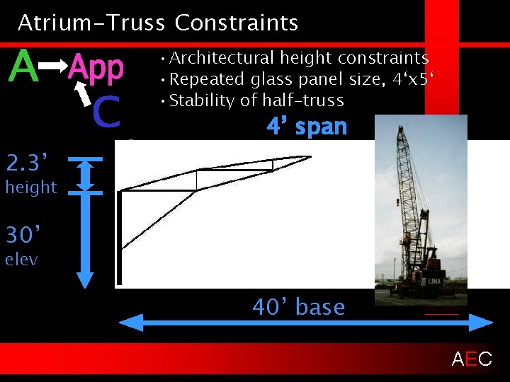
Atrium-Truss Constraints • Architectural height constraints • Repeated glass panel size, 4‘x 5‘ • Stability of half-truss 2. 3’ 8’ span 4’ span height 30’ elev 20’ span between trusses 40’ base AEC
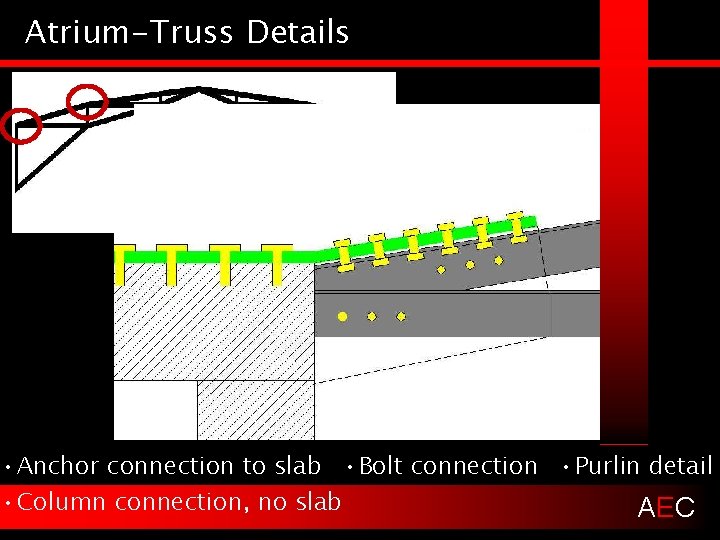
Atrium-Truss Details • Anchor connection to slab • Bolt connection • Purlin detail • Column connection, no slab AEC
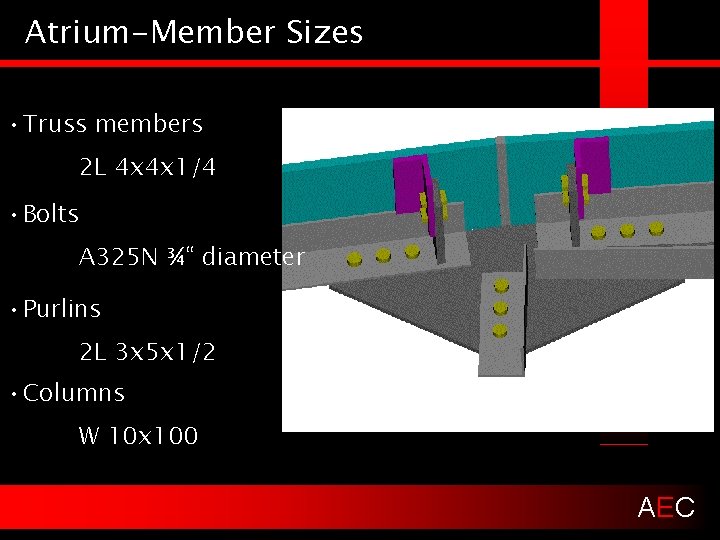
Atrium-Member Sizes • Truss members 2 L 4 x 4 x 1/4 • Bolts A 325 N ¾“ diameter • Purlins 2 L 3 x 5 x 1/2 • Columns W 10 x 100 AEC
Learning Experience-What did we learn here • Computer • Necessity • Communication New hardware & software • Be Clear & Listen • Collaboration Meltdown flexibility Asynchronous vs. Synchronous • 1 Goal. Down • Breaking Discipline Lines Create clear. Team sketches • Act as one AEC
Thanks to mentors: • Robert Alvarado • Helmut Krawinkler • Greg Luth • Eric Horn • Alfred Koelliker • Chuck Madewell • Bob Tatum • James Bartone • Boyd Paulson • Scott Dennis . . . and Questions? AEC