Momentum Transport Flow in Phenomena Porous Media Advanced

- Slides: 59
Momentum Transport: Flow in Phenomena Porous Media & Advanced Transport Packed Module 4 - Beds Lecture 16 Dr. R. Nagarajan Professor Dept of Chemical Engineering IIT Madras
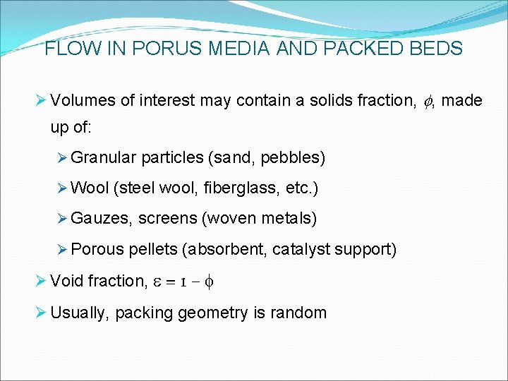
FLOW IN PORUS MEDIA AND PACKED BEDS Ø Volumes of interest may contain a solids fraction, f, made up of: Ø Granular particles (sand, pebbles) Ø Wool (steel wool, fiberglass, etc. ) Ø Gauzes, screens (woven metals) Ø Porous pellets (absorbent, catalyst support) Ø Void fraction, e = 1 – f Ø Usually, packing geometry is random
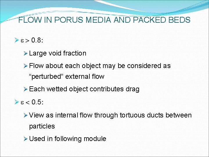
FLOW IN PORUS MEDIA AND PACKED BEDS Ø e > 0. 8: Ø Large void fraction Ø Flow about each object may be considered as “perturbed” external flow Ø Each wetted object contributes drag Ø e < 0. 5: Ø View as internal flow through tortuous ducts between particles Ø Used in following module
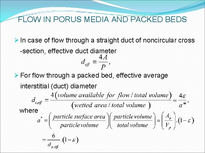
FLOW IN PORUS MEDIA AND PACKED BEDS Ø In case of flow through a straight duct of noncircular cross -section, effective duct diameter Ø For flow through a packed bed, effective average interstitial (duct) diameter where
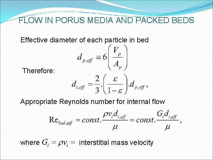
FLOW IN PORUS MEDIA AND PACKED BEDS Effective diameter of each particle in bed Therefore: Appropriate Reynolds number for internal flow where interstitial mass velocity
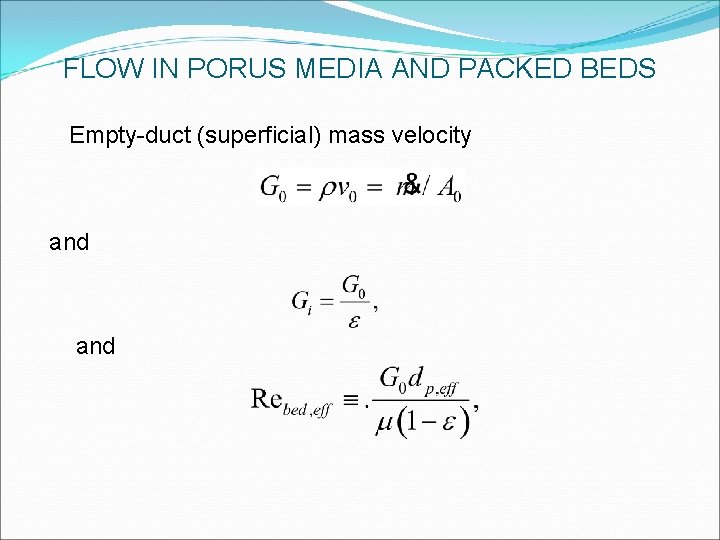
FLOW IN PORUS MEDIA AND PACKED BEDS Empty-duct (superficial) mass velocity and
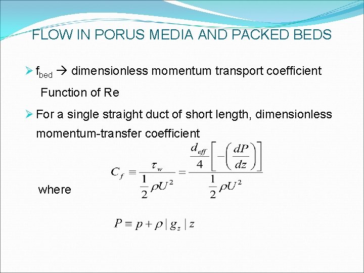
FLOW IN PORUS MEDIA AND PACKED BEDS Ø fbed dimensionless momentum transport coefficient Function of Re Ø For a single straight duct of short length, dimensionless momentum-transfer coefficient where
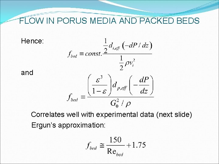
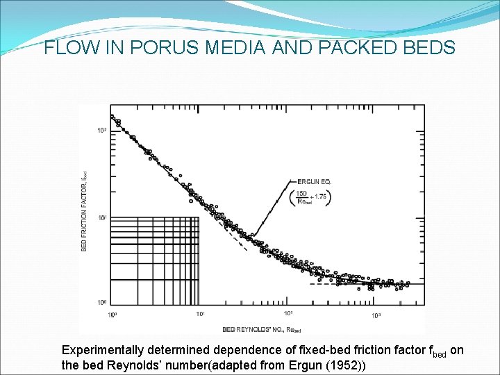
FLOW IN PORUS MEDIA AND PACKED BEDS Hence: and Correlates well with experimental data (next slide) Ergun’s approximation:
FLOW IN PORUS MEDIA AND PACKED BEDS Experimentally determined dependence of fixed-bed friction factor fbed on the bed Reynolds’ number(adapted from Ergun (1952))
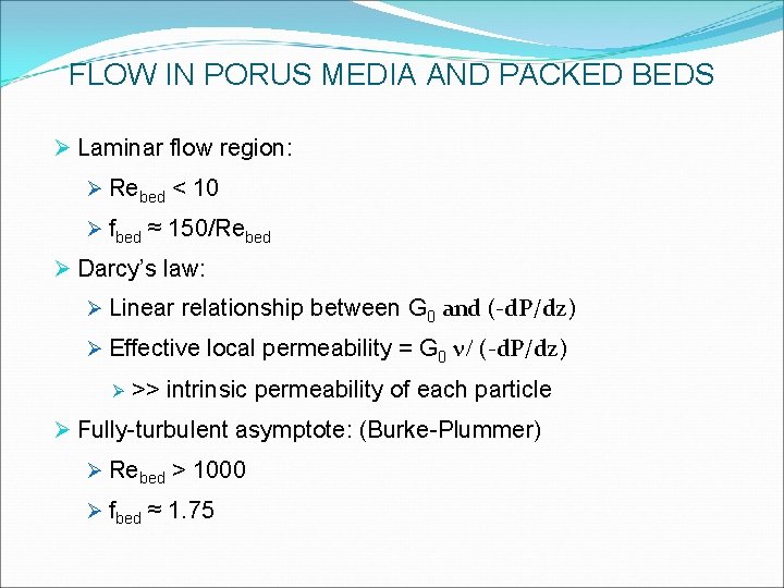
FLOW IN PORUS MEDIA AND PACKED BEDS Ø Laminar flow region: Ø Rebed < 10 Ø fbed ≈ 150/Rebed Ø Darcy’s law: Ø Linear relationship between G 0 and (-d. P/dz) Ø Effective local permeability = G 0 n/ (-d. P/dz) Ø >> intrinsic permeability of each particle Ø Fully-turbulent asymptote: (Burke-Plummer) Ø Rebed > 1000 Ø fbed ≈ 1. 75
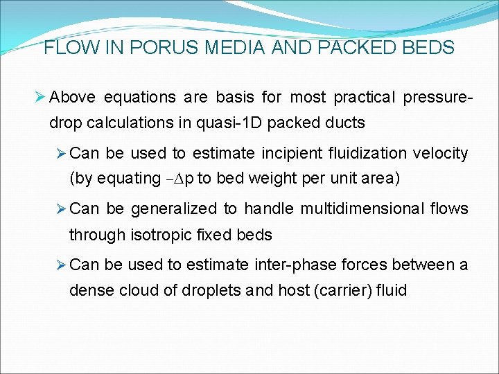
FLOW IN PORUS MEDIA AND PACKED BEDS Ø Above equations are basis for most practical pressure- drop calculations in quasi-1 D packed ducts Ø Can be used to estimate incipient fluidization velocity (by equating –Dp to bed weight per unit area) Ø Can be generalized to handle multidimensional flows through isotropic fixed beds Ø Can be used to estimate inter-phase forces between a dense cloud of droplets and host (carrier) fluid
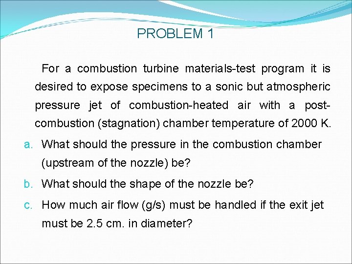
PROBLEM 1 For a combustion turbine materials-test program it is desired to expose specimens to a sonic but atmospheric pressure jet of combustion-heated air with a postcombustion (stagnation) chamber temperature of 2000 K. a. What should the pressure in the combustion chamber (upstream of the nozzle) be? b. What should the shape of the nozzle be? c. How much air flow (g/s) must be handled if the exit jet must be 2. 5 cm. in diameter?
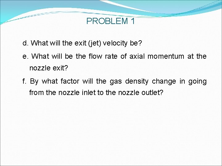
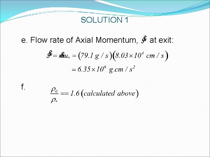
PROBLEM 1 d. What will the exit (jet) velocity be? e. What will be the flow rate of axial momentum at the nozzle exit? f. By what factor will the gas density change in going from the nozzle inlet to the nozzle outlet?
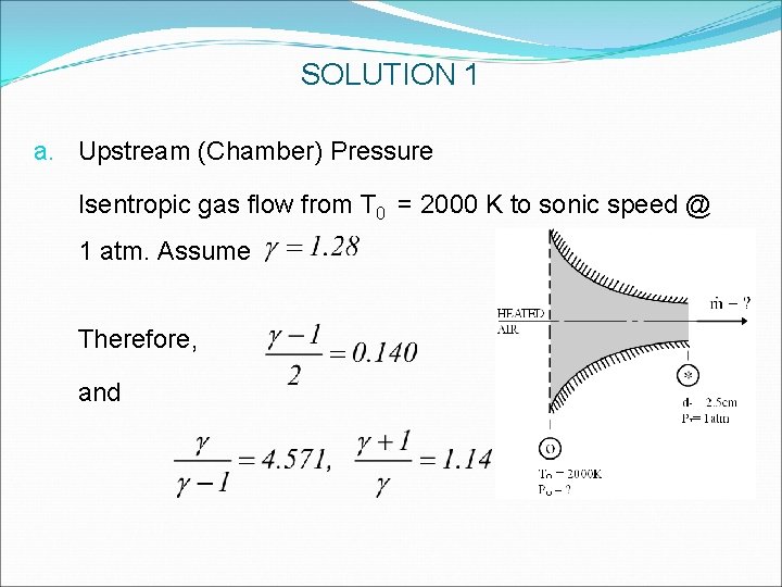
SOLUTION 1 a. Upstream (Chamber) Pressure Isentropic gas flow from T 0 = 2000 K to sonic speed @ 1 atm. Assume Therefore, and
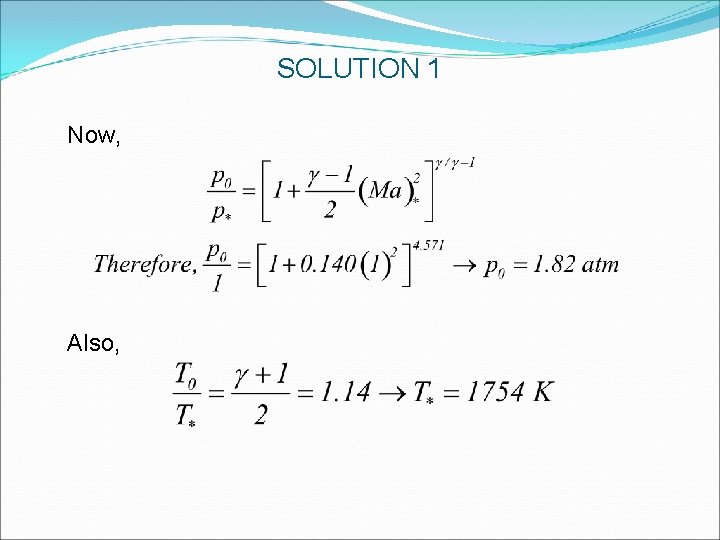
SOLUTION 1 Now, Also,
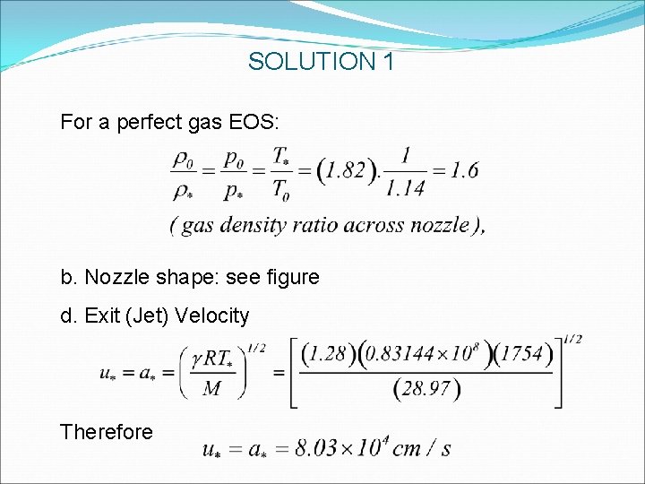
SOLUTION 1 For a perfect gas EOS: b. Nozzle shape: see figure d. Exit (Jet) Velocity Therefore
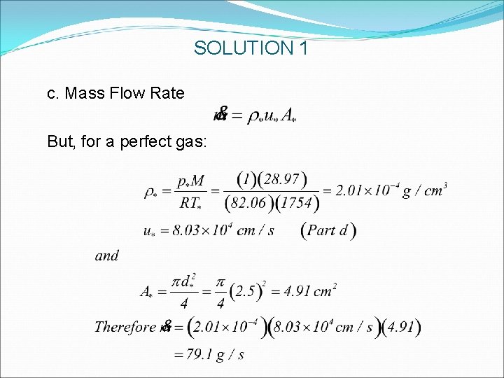
SOLUTION 1 c. Mass Flow Rate But, for a perfect gas:
SOLUTION 1 e. Flow rate of Axial Momentum, f. at exit:
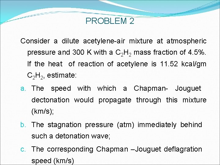
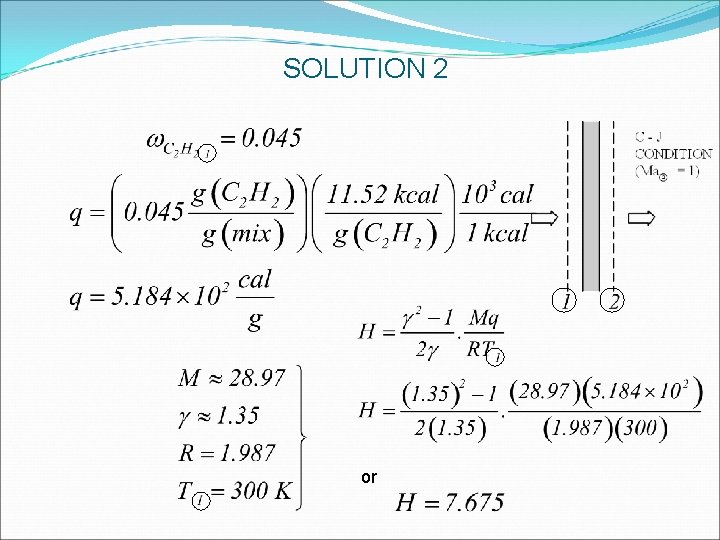
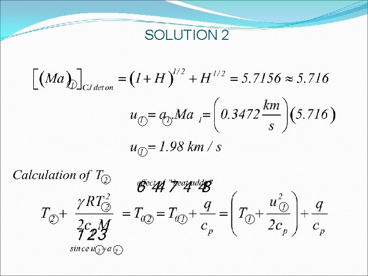
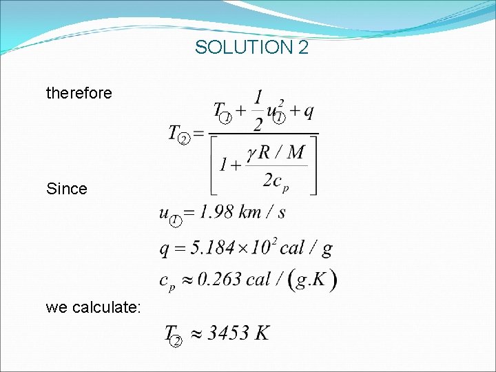
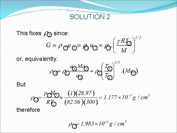
PROBLEM 2 Consider a dilute acetylene-air mixture at atmospheric pressure and 300 K with a C 2 H 2 mass fraction of 4. 5%. If the heat of reaction of acetylene is 11. 52 kcal/gm C 2 H 2, estimate: a. The speed with which a Chapman- Jouguet dectonation would propagate through this mixture (km/s); b. The stagnation pressure (atm) immediately behind such a detonation wave; c. The corresponding Chapman –Jouguet deflagration speed (km/s)
SOLUTION 2 or
SOLUTION 2
SOLUTION 2 therefore Since we calculate:
SOLUTION 2 This fixes since: 0 or, equivalently: But therefore
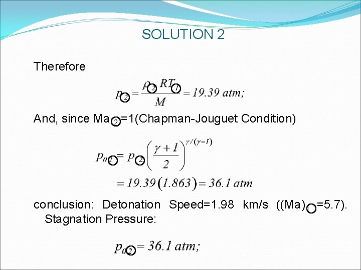
SOLUTION 2 Therefore And, since Ma 2 =1(Chapman-Jouguet Condition) conclusion: Detonation Speed=1. 98 km/s ((Ma)1 =5. 7). Stagnation Pressure:
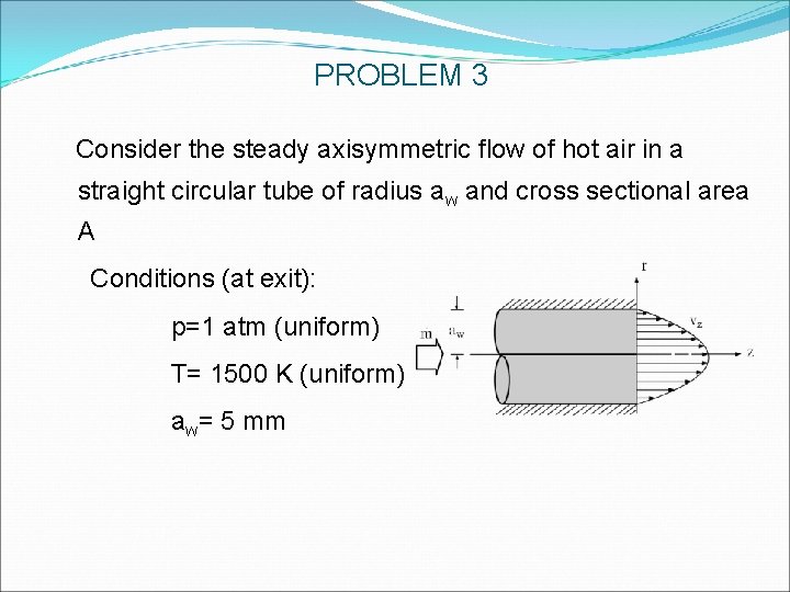
PROBLEM 3 Consider the steady axisymmetric flow of hot air in a straight circular tube of radius aw and cross sectional area A Conditions (at exit): p=1 atm (uniform) T= 1500 K (uniform) aw= 5 mm
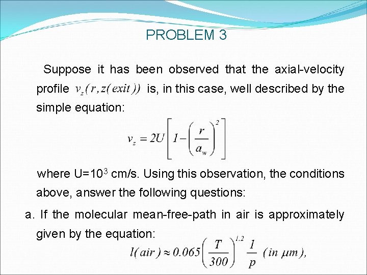
PROBLEM 3 Suppose it has been observed that the axial-velocity profile is, in this case, well described by the simple equation: where U=103 cm/s. Using this observation, the conditions above, answer the following questions: a. If the molecular mean-free-path in air is approximately given by the equation:
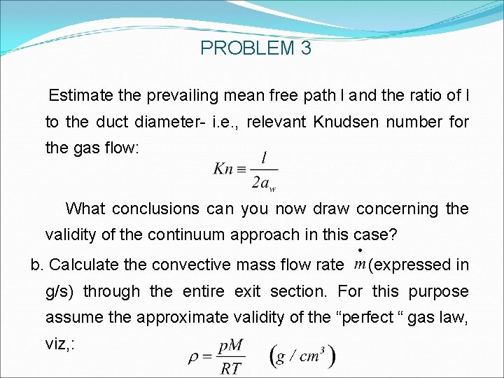
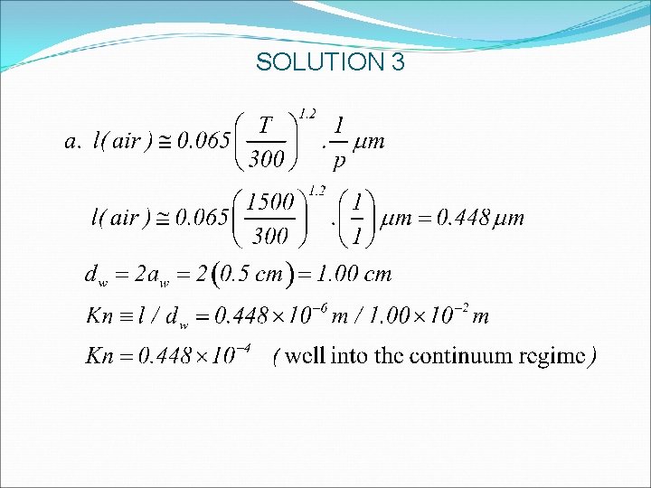
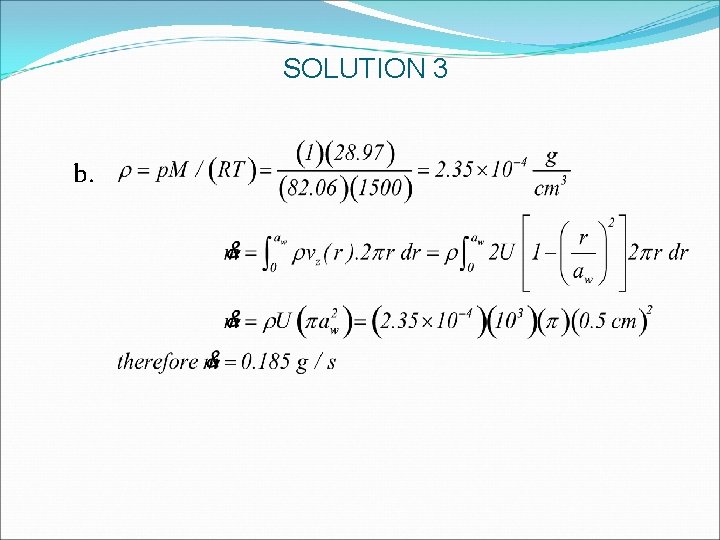
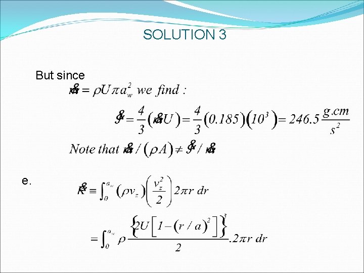
PROBLEM 3 Estimate the prevailing mean free path l and the ratio of l to the duct diameter- i. e. , relevant Knudsen number for the gas flow: What conclusions can you now draw concerning the validity of the continuum approach in this case? b. Calculate the convective mass flow rate (expressed in g/s) through the entire exit section. For this purpose assume the approximate validity of the “perfect “ gas law, viz, :
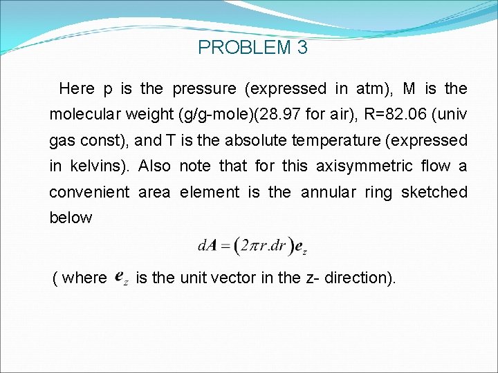
PROBLEM 3 Here p is the pressure (expressed in atm), M is the molecular weight (g/g-mole)(28. 97 for air), R=82. 06 (univ gas const), and T is the absolute temperature (expressed in kelvins). Also note that for this axisymmetric flow a convenient area element is the annular ring sketched below ( where is the unit vector in the z- direction).
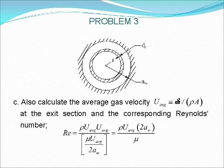
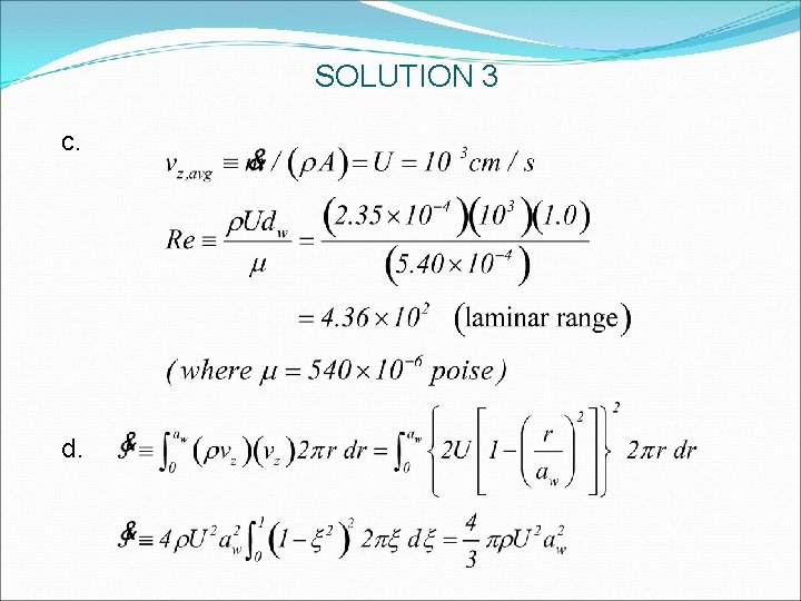
PROBLEM 3 c. Also calculate the average gas velocity at the exit section and the corresponding Reynolds’ number;
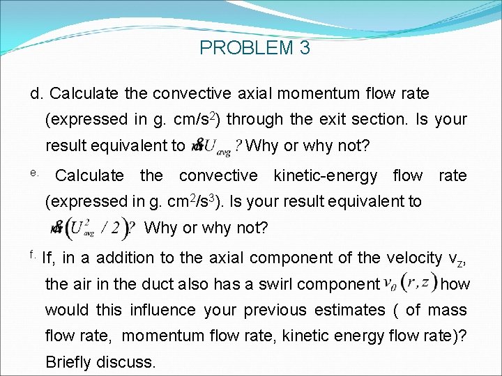
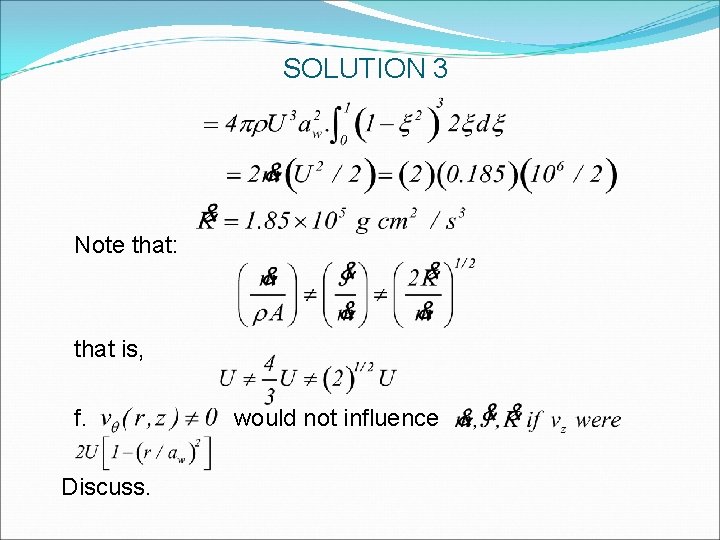
PROBLEM 3 d. Calculate the convective axial momentum flow rate (expressed in g. cm/s 2) through the exit section. Is your result equivalent to e. Why or why not? Calculate the convective kinetic-energy flow rate (expressed in g. cm 2/s 3). Is your result equivalent to Why or why not? f. If, in a addition to the axial component of the velocity vz, the air in the duct also has a swirl component how would this influence your previous estimates ( of mass flow rate, momentum flow rate, kinetic energy flow rate)? Briefly discuss.
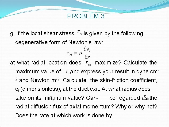
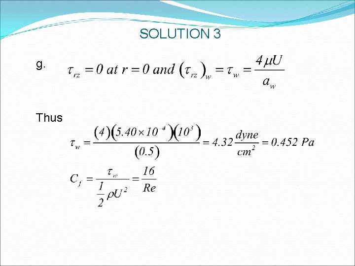
PROBLEM 3 g. If the local shear stress is given by the following degenerative form of Newton’s law: at what radial location does maximum value of 2 maximize? Calculate the and express your result in dyne cm- and Newton m-2. Calculate the skin-friction coefficient, cf (dimensionless), at the duct exit. At what radius does take on its minimum value? Can- be regarded as the radial diffusion flux of axial momentum? Why or why not? Does the rate at which work is done by
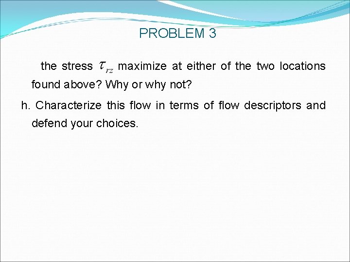
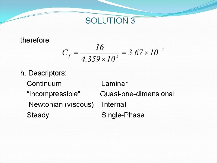
PROBLEM 3 the stress maximize at either of the two locations found above? Why or why not? h. Characterize this flow in terms of flow descriptors and defend your choices.
SOLUTION 3
SOLUTION 3 b.
SOLUTION 3 c. d.
SOLUTION 3 But since e.
SOLUTION 3 Note that: that is, f. Discuss. would not influence
SOLUTION 3 g. Thus
SOLUTION 3 therefore h. Descriptors: Continuum Laminar “Incompressible” Quasi-one-dimensional Newtonian (viscous) Internal Steady Single-Phase
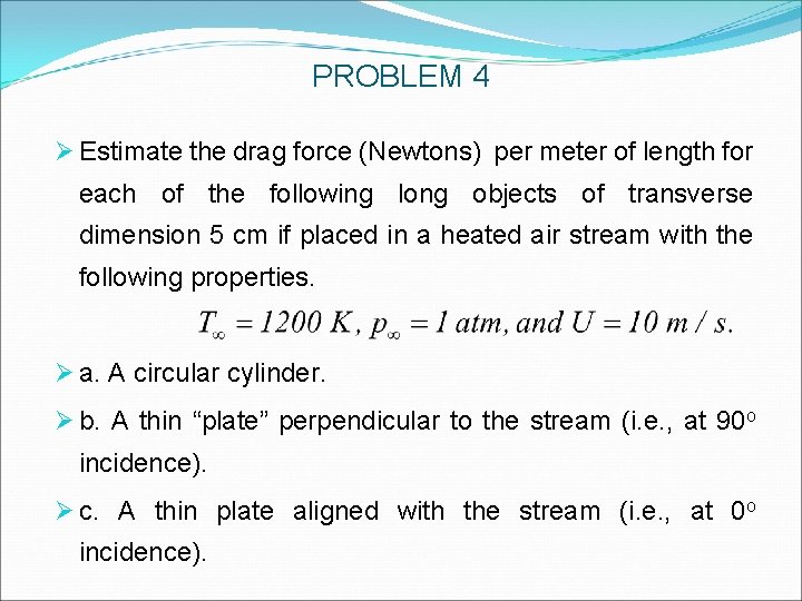
PROBLEM 4 Ø Estimate the drag force (Newtons) per meter of length for each of the following long objects of transverse dimension 5 cm if placed in a heated air stream with the following properties. Ø a. A circular cylinder. Ø b. A thin “plate” perpendicular to the stream (i. e. , at 90 o incidence). Ø c. A thin plate aligned with the stream (i. e. , at 0 o incidence).
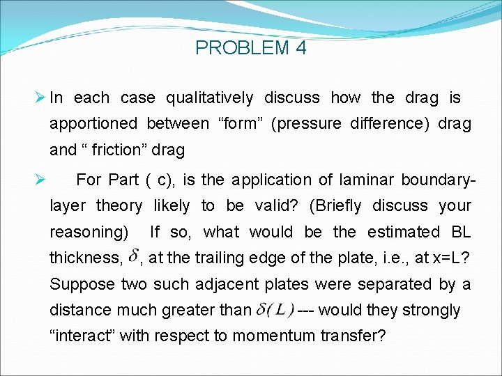
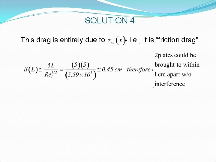
PROBLEM 4 Ø In each case qualitatively discuss how the drag is apportioned between “form” (pressure difference) drag and “ friction” drag Ø For Part ( c), is the application of laminar boundarylayer theory likely to be valid? (Briefly discuss your reasoning) If so, what would be the estimated BL thickness, , at the trailing edge of the plate, i. e. , at x=L? Suppose two such adjacent plates were separated by a distance much greater than --- would they strongly “interact” with respect to momentum transfer?
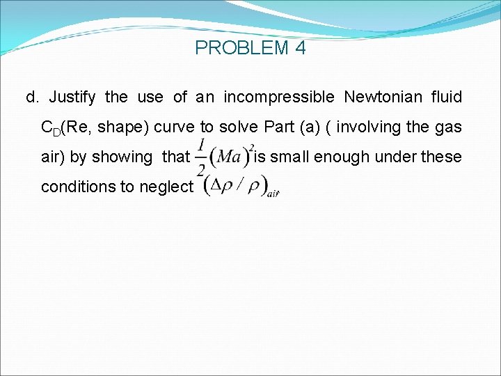
PROBLEM 4 d. Justify the use of an incompressible Newtonian fluid CD(Re, shape) curve to solve Part (a) ( involving the gas air) by showing that conditions to neglect is small enough under these.
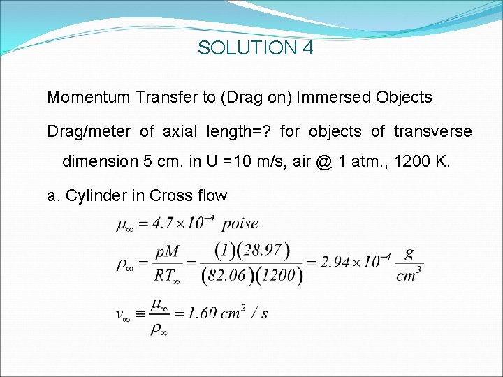
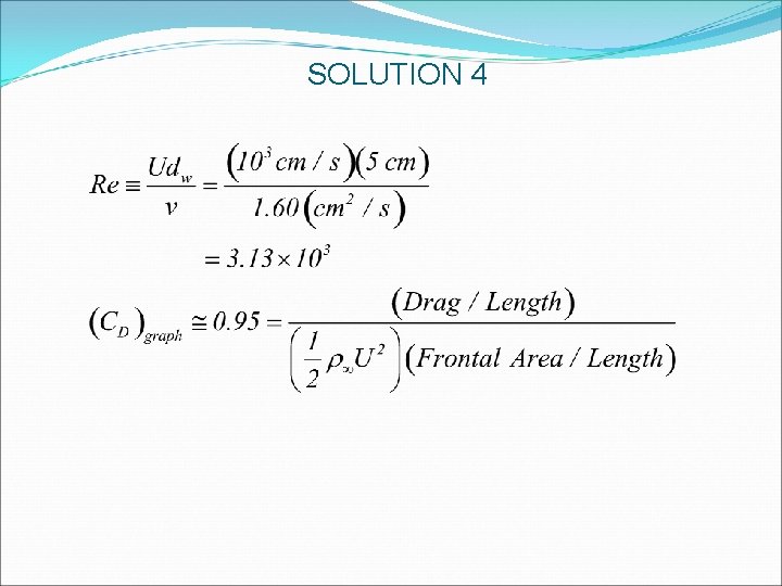
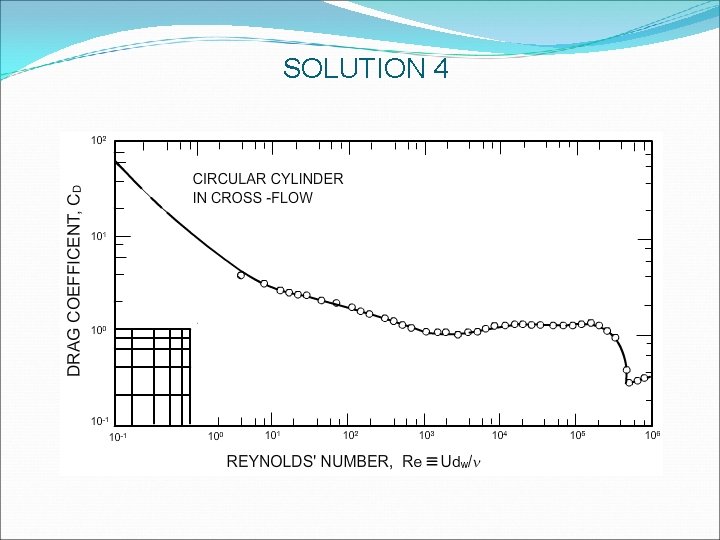
SOLUTION 4 Momentum Transfer to (Drag on) Immersed Objects Drag/meter of axial length=? for objects of transverse dimension 5 cm. in U =10 m/s, air @ 1 atm. , 1200 K. a. Cylinder in Cross flow
SOLUTION 4
SOLUTION 4
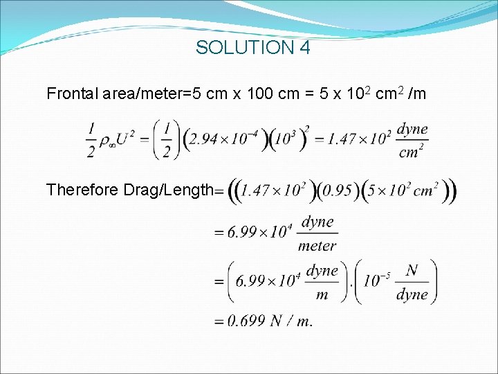
SOLUTION 4 Frontal area/meter=5 cm x 100 cm = 5 x 102 cm 2 /m Therefore Drag/Length
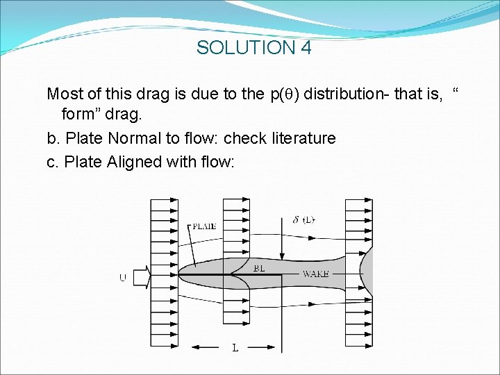
SOLUTION 4 Most of this drag is due to the p(q) distribution- that is, “ form” drag. b. Plate Normal to flow: check literature c. Plate Aligned with flow:
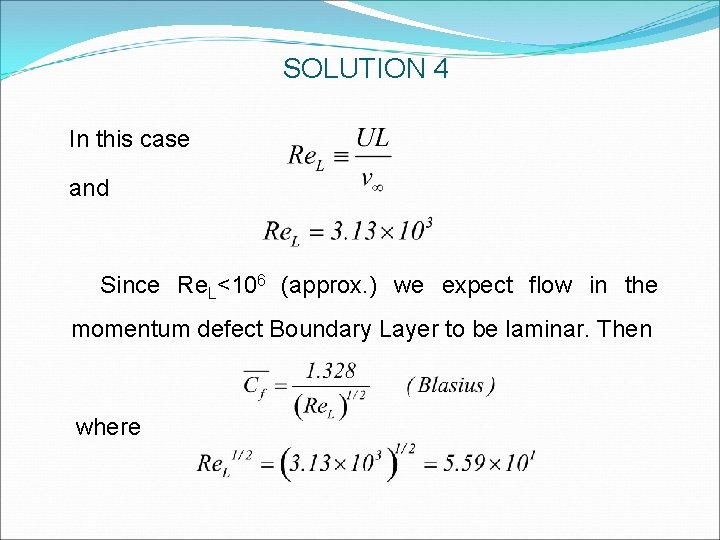
SOLUTION 4 In this case and Since Re. L<106 (approx. ) we expect flow in the momentum defect Boundary Layer to be laminar. Then where
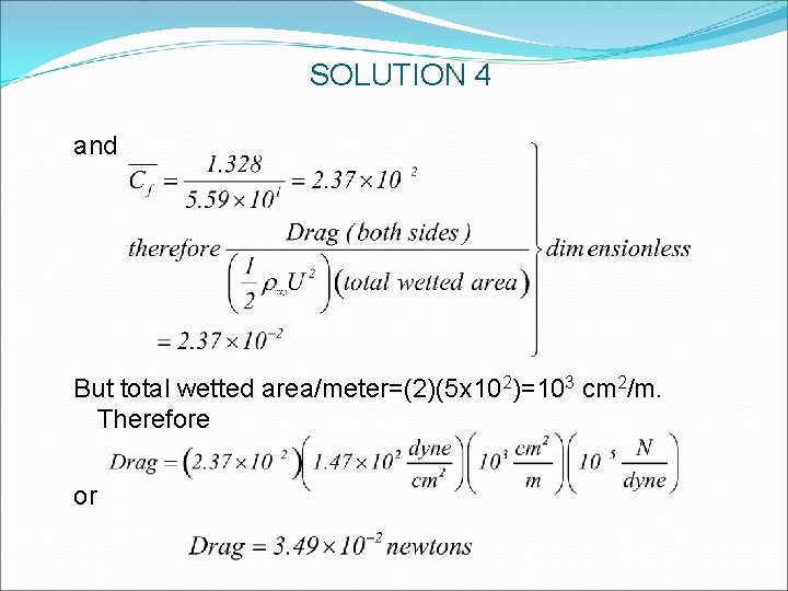
SOLUTION 4 and But total wetted area/meter=(2)(5 x 102)=103 cm 2/m. Therefore or
SOLUTION 4 This drag is entirely due to - i. e. , it is “friction drag”
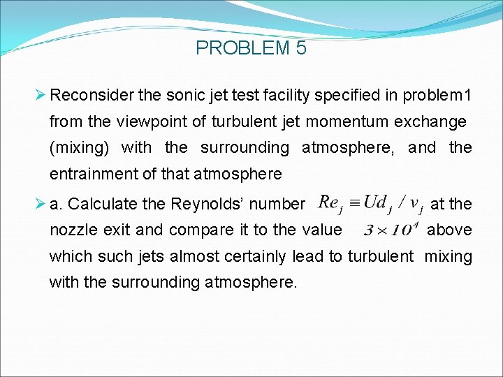
PROBLEM 5 Ø Reconsider the sonic jet test facility specified in problem 1 from the viewpoint of turbulent jet momentum exchange (mixing) with the surrounding atmosphere, and the entrainment of that atmosphere Ø a. Calculate the Reynolds’ number nozzle exit and compare it to the value at the above which such jets almost certainly lead to turbulent mixing with the surrounding atmosphere.
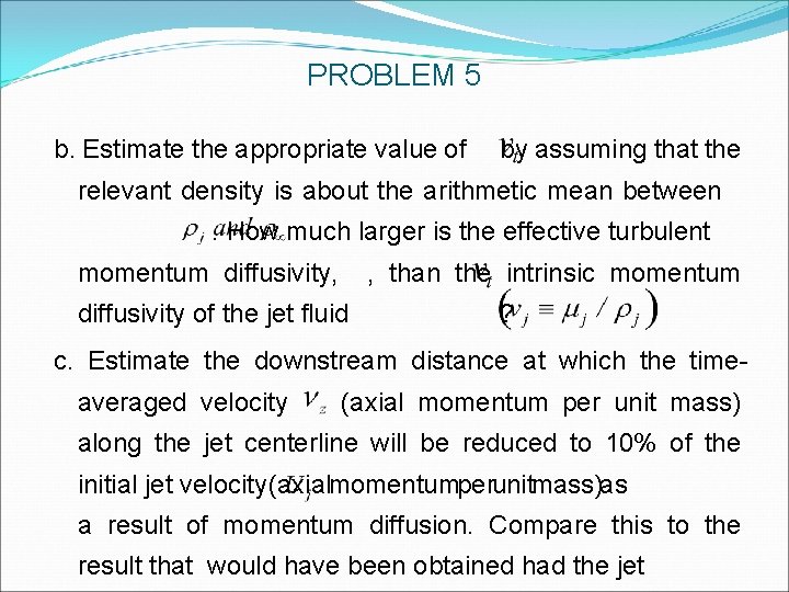
PROBLEM 5 b. Estimate the appropriate value of by assuming that the relevant density is about the arithmetic mean between. How much larger is the effective turbulent momentum diffusivity, , than the intrinsic momentum diffusivity of the jet fluid ? c. Estimate the downstream distance at which the timeaveraged velocity (axial momentum per unit mass) along the jet centerline will be reduced to 10% of the initial jet velocity (axialmomentumperunitmass)as a result of momentum diffusion. Compare this to the result that would have been obtained had the jet
PROBLEM 5 remained laminar (with kinematic viscosity ). d. At this location what is the approximate ratio between the entrained (laboratory air) mass flow and the “primary” (combustion-heated air) jet?
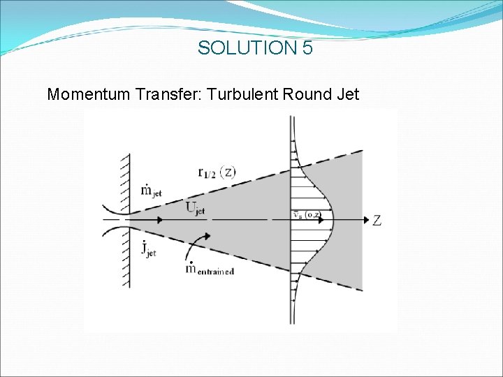
SOLUTION 5 Momentum Transfer: Turbulent Round Jet
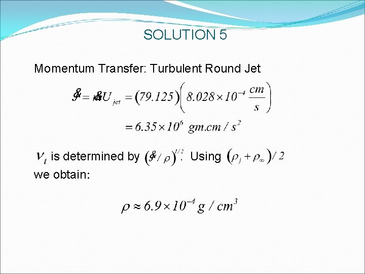
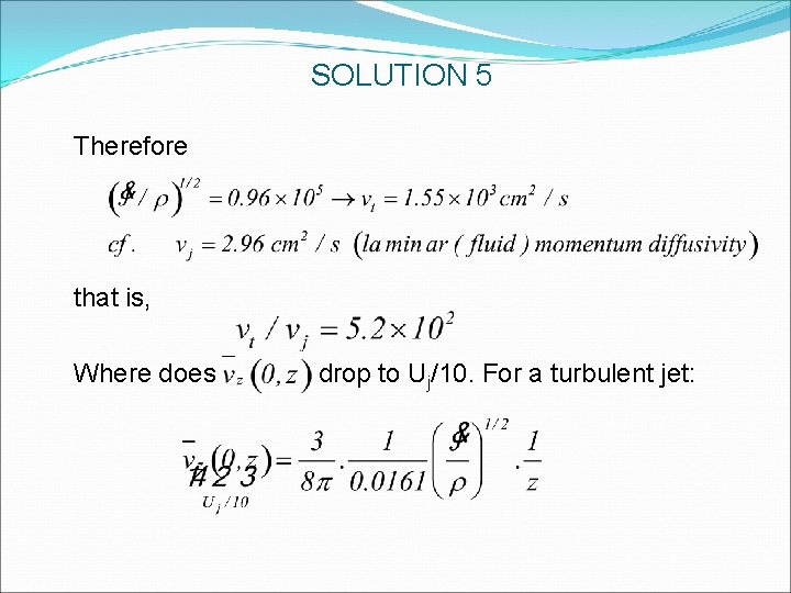
SOLUTION 5 Momentum Transfer: Turbulent Round Jet is determined by we obtain: . Using
SOLUTION 5 Therefore that is, Where does drop to Uj/10. For a turbulent jet:
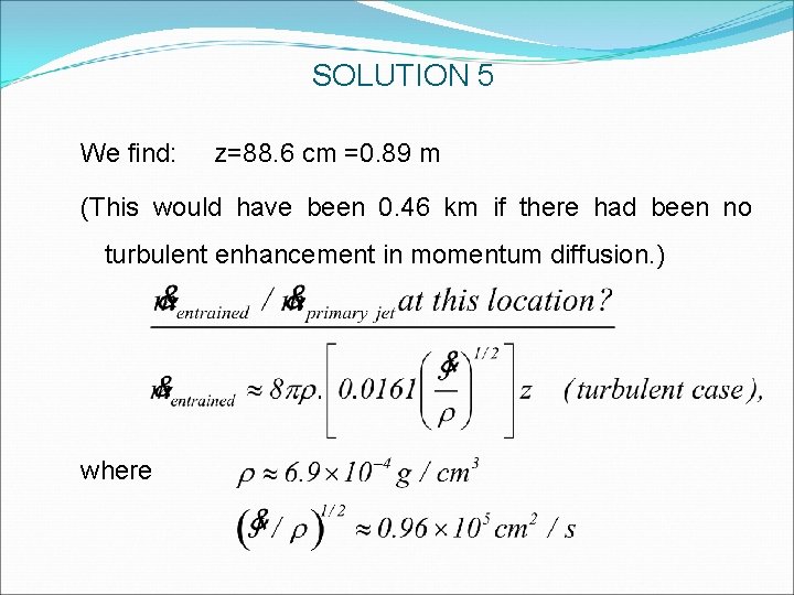
SOLUTION 5 We find: z=88. 6 cm =0. 89 m (This would have been 0. 46 km if there had been no turbulent enhancement in momentum diffusion. ) where
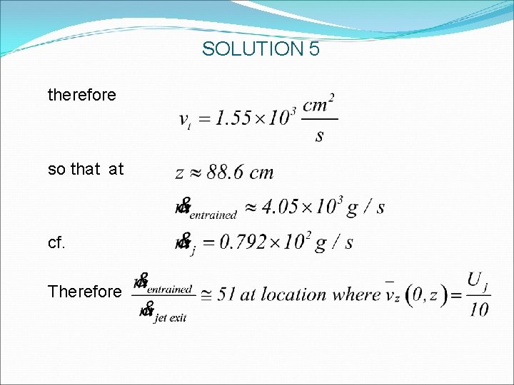
SOLUTION 5 therefore so that at cf. Therefore
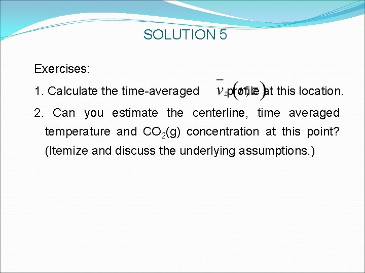
SOLUTION 5 Exercises: 1. Calculate the time-averaged profile at this location. 2. Can you estimate the centerline, time averaged temperature and CO 2(g) concentration at this point? (Itemize and discuss the underlying assumptions. )