Moments of Force MOMENTS What is moment A


- Slides: 49

Moments of Force

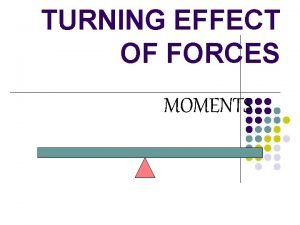
MOMENTS What is moment? A force can cause many things to move or stop. When a force causes an object to turn, this turning effect is called moments. Example: A person sitting on a see-saw. Mechanical Technology Curriculum Coordination & Support

Types Of Moments There are 2 types moments: � Clockwise moment � Anticlockwise moment Mechanical Technology Curriculum Coordination & Support

Everyday Examples 1. 2. 3. 4. 5. 6. turning a door knob opening a door scissors turning a steering wheel crane at the construction sites lifting objects electrical fan Mechanical Technology Curriculum Coordination & Support

Everyday Examples 7. spanner & nut Mechanical Technology Curriculum Coordination & Support

Everyday Examples 8. Wheelbarrow Mechanical Technology Curriculum Coordination & Support

What does the turning effect of a force depend on? 1. force 2. perpendicular distance between force and pivot Mechanical Technology Curriculum Coordination & Support

Turning Effect of a Force � � Note: turning effect = moment = torque The moment of a force is its turning effect about a pivot Mechanical Technology Curriculum Coordination & Support

Turning Effect of a Force Moments is the product of the force and the perpendicular distance from the pivot to the line of action of the force. d Mechanical Technology Curriculum Coordination & Support

CALCULATING MOMENTS Moment = force perpendicular distance between force and pivot In symbols: Moments = F d Unit for moments: Newton-metre (Nm) d Weight => F Mechanical Technology Curriculum Coordination & Support

Worked Example 1: A cat of weight 20 N stands on one end of a see-saw and the distance between the cat and the pivot is 3 m, find the moment. Solution: In this case the cat is causing a clockwise moment. Clockwise moment =Fxd = 20 x 3 = 60 Nm d = 3 m F = 20 N Mechanical Technology Curriculum Coordination & Support

Worked Example 2: A duck stands on one end of a see-saw, 5 m away from the pivot. If the weight of the duck is 10 N, find the moment. Solution: The duck’s weight is causing an anticlockwise moment. Anticlockwise moment =Fxd = 10 x 5 = 50 Nm d = 5 m F = 10 N Mechanical Technology Curriculum Coordination & Support

It is easy to balance two objects of the same weight � Anticlockwis • Anticlockwise e moment • Clockwise � Antimoment clockwise moment Mechanical Technology Curriculum Coordination & Support

Is it possible to balance a objects of different weight? Mechanical Technology Curriculum Coordination & Support

Principle of Moments For an object to be in equilibrium(stable/not moving), the total clockwise moment must be equal to the anticlockwise moment about the same pivot. weight pivot It is the fixed(non moving) point Mechanical Technology Curriculum Coordination & Support

SOLVING PROBLEMS RELATED TO PRINCIPLE OF MOMENTS Step 1: Identify what are the forces that will give rise to clockwise / anticlockwise moment Step 2: Find the clockwise / anticlockwise moment Step 3: Equate the clockwise and anticlockwise moments Mechanical Technology Curriculum Coordination & Support

Worked Example 3 Class exercise 6 m d 30 N 10 N Find the value of d. Mechanical Technology Curriculum Coordination & Support

Step 1: Identify what are the forces that will give rise to clockwise / anticlockwise moment Mechanical Technology Curriculum Coordination & Support

Worked Example 3 6 m d 30 N Clockwise moment 10 N Anticlockwise moment Find the value of d. Mechanical Technology Curriculum Coordination & Support

Step 2: Find the clockwise / anticlockwise moment Mechanical Technology Curriculum Coordination & Support

Worked Example 3 6 m d Anticlockwise moment 30 N 10 N Clockwise moment Find the value of d. Solution: Clockwise moment = Force x distance between force and pivot = 30 x d = 30 d Nm Anticlockwise moment = Force x distance between force and pivot = 10 x 6 = 60 Nm Mechanical Technology Curriculum Coordination & Support

Step 3: Equate the clockwise and anticlockwise moments Mechanical Technology Curriculum Coordination & Support

Worked Example 3 6 m d Anticlockwise moment 30 N 10 N Clockwise moment Find the value of d. Using the principle of moments, Clockwise moment = Anti-clockwise moment 30 d = 60 30 d =2 m Mechanical Technology Curriculum Coordination & Support

Points to note: 1. The unit force must be in Newtons, the unit for distance must be in metres. 2. The distance must measured perpendicularly from the force to the pivot. Mechanical Technology Curriculum Coordination & Support

Calculating reactions � � Reactions are counter-forces that are exerted when a beam is subjected to one or more vertical downward forces which causes the beam to be in equilibrium. To calculate the 9 Nshear forces and bending moments in a beam, we first calculate the reactions. 1 m 2 m RR

Calculating reactions � To calculate the reactions (force), we apply the law of moments. � This law is defined as follows: � If a simple lever, capable of turning about a given hinge point or fulcrum, is loaded in such a manner as to keep it in equilibrium, the sum of all the clockwise moments taken about the fulcrum will equal the sum of all the anticlockwise moments. � When calculating reactions, start by drawing the beam on the top left-hand side of a double page in your exercise book. � Do all the required diagrams on the left-hand page and all the calculations on the right-hand side.

Calculating reactions • Open your notebooks and complete the example as it is explained! • Draw the following diagram 9 N RL 1 m 2 m RR Take moments about reaction left (RL): forces = forces RR x 3 m = 9 N x 1 m ∴ RR = (9 N x 1 m) 3 m ∴ RR = 3 N Take moments about reaction right(RR): forces = forces RL x 3 m = 9 N x 2 m ∴ RL = (9 N x 2 m) 3 m ∴ RL = 6 N

Test Calculations � The beam is in equilibrium; therefore the sum of upward forces must equal the sum of downward forces. i. e. Forces RL + RR 6 N+3 N 9 N = = 9 N Forces downward forces 9 N 9 N RL 1 m =6 N 2 m RR =3 N

Drawing a shear force diagram � Shear forces are defined as: � The shearing force at any point along a loaded beam is the algebraic sum of all the vertical forces acting to one side of the point on the beam. � � We draw a shear force diagram to determine the magnitude of the shearing forces at any point of a loaded beam and in so doing identify areas of weakness. This is done in order to take the appropriate design action by using material which has been tested to withstand the calculated shear forces.

Drawing a shear force diagram 9 N RL 1 m 6 N. 2 m • RL = 6 N up • FORCE = 9 N down • RR = 3 N up RR + 0 N -3 N • When you are finished drawing the shear force diagram always shade the graph. • The flashing circle indicates the point at which the beam is most likely to SHEAR (break).

CALCULATE BENDING MOMENTS 9 N COVER WITH A PAGE 6 N 1 m � 2 m 3 N Bm = (9 N X 1) – (9 X 0) = 12, 5 Nm

BENDING MOMENTS DIAGRAM 9 N RL 1 m 6 N. Start with datum line � Plot bending moments � 2 m RR 0 N 0 N -3 N Bm=12, 5 Nm O Nm � Join O Nm 12, 5 Nm points Shade graph and � Indicate the greatest bending moment � + - � Bm=

Example 1 � A beam is subjected to three point loads and is supported at either end by RL and RR. 1. Calculate: a. The magnitudes of RL and RR b. The bending moments at points A, B and C 2. Draw the following: a. The sheer force diagram using a scale of 1 cm = 1 m and 1 cm = 1 N b. The bending moment diagram and indicate the greatest bending moment, using a scale of 1 cm = 1 m and 1 cm = 2 Nm.

Example 1 � � Start this example on a new double page. We will only complete the shear force diagram.

� � Example 1 - CALCULATE REACTIONS Take moments about RL (RR X 8)=(4 X 2)+(5 X 4)+(3 X 6) RR= (8+20+18)/8 RR = 5, 75 N 4 N 5 N 3 N RL 2 m A 2 m B 2 m C 2 m RR

CALCULATE REACTIONS Take moments about RR �(RL X 8)=(3 X 2)+(5 X 4)+(4 X 6) � RL= (6+20+24)/8 � RL = 6, 25 N 4 N 5 N 3 N RL 2 m A 2 m B 2 m C 2 m RR

CALCULATE REACTIONS � � � All up forces = all down forces 5, 75 N +6, 25 N = 4 N+5 N+3 N 12 N = 12 N 4 N RL=5, 75 N 5 N 3 N RR=6, 25 N

SHEAR FORCE DIAGRAM 4 N 5 N 6, 25 N � RL 3 N 5, 75 N 6, 25 N 2, 25 N 0 N 0 N - 2, 75 N -5. 75 N = 6, 25 N up � Force = 4 N down � Force = 5 N down � Force = 3 N down � RR = 5, 75 N up � Remember to shade the graph

CALCULATE BENDING MOMENTS 4 N 5 N 3 N COVER WITH A PAGE 6. 25 N � � � 2 m A 2 m B 2 m C 2 m 5. 75 N Bm A = (6, 25 X 2) – (4 X 0) = 12, 5 N. m Bm B = (6, 25 X 4) – (4 X 2) = 17 N. m Bm C = (6, 25 X 6) – (4 X 4) – (5 X 2) = 11, 5 N. m

BENDING MOMENT DIAGRAM 4 N 6, 25 N A 5 N B Start with datum line � Plot bending moments � 3 N C � Bm A 12, 5 Nm � Bm B 17 Nm � Bm C 11, 5 Nm 5, 75 N Join points � Shade graph and � Indicate the greatest bending moment � Bm B 17 Nm Bm A 12, 5 Nm 0 Nm Bm C 11, 5 Nm 0 Nm

SHEER FORCES AND BENDING MOMENTS Point loads and Uniformly Distributed Loads (UDL’s)

CALCULATE REACTIONS � 3 N/m 5 N RL 2 m A 2 m B 3 N 2 m C 2 m RR First convert UDL to point load

CALCULATE REACTIONS � 6 N 5 N � 3 N � 1 m l 1 m RL 2 m A 2 m B 2 m C 2 m RR � First convert UDL of 3 N/m to a point load 3 N/m X 2 m = 6 N 6 N point load placed in centre of UDL. All calculations are done with the point loads only

CALCULATE REACTIONS 6 N 5 N RL 3 N 1 m l 1 m 2 m A 2 m B 2 m C 2 m RR Take moments about RL � � (RR x 8) = (6 x 3) + (5 x 4) + (3 x 6) (RR x 8) = (18 + 20 +18) RR = 56/8 RR = 7 N

CALCULATE REACTIONS 6 N 5 N 3 N 1 m l 1 m RL � � 2 m A 2 m B 2 m C 2 m RR Take moments about RR (RL X 8) = (3 X 2) + (5 X 4) + (6 X 5) RL = (6+20+30) /8 RL = 7 N

CALCULATE REACTIONS 6 N 5 N 3 N 1 m l 1 m RL � 2 m A 2 m B 2 m C 2 m RR All up forces = all down forces 7 N+7 N =6 N+5 N+3 N 14 N = 14 N

SHEAR FORCE DIAGRAM 6 N 5 N 3 N � 7 N 7 N 7 N 1 m l 1 m 7 N � � 1 N 0 N 0 N � -4 N -7 N RR = 7 N up UDL = 6 N down Force = 5 N down Force = 3 N down RL = 7 N up Shade the graph

CALCULATE BENDING MOMENTS 6 N 5 N 3 N Cover with a page 1 m l 1 m 7 N � � � 2 m A 2 m B 2 m C 2 m 7 N Bm A = (7 X 2) = 14 N. m Bm B = (7 X 4) – (6 X 1) = 22 N. m Bm C = (7 X 6) – (6 X 3) – (5 X 2) = 14 N. m

BENDING MOMENT DIAGRAM 6 N � Start 5 N 7 N 2 m A 2 m B with datum line � Plot bending moments 3 N 2 m C 2 m 7 N � Bm � Join A = 14 N B = 22 N C = 14 N points � NB: UDL’s are always joined with a curved line � Shade the graph and � indicate the greatest bending moment 0 Nm
 What is moment
 What is moment of force
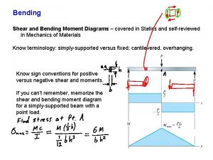
 How to draw sfd and bmd for simply supported beam
 Couple system
 Draw the shear and moment diagrams for the beam
 Moment of force about an axis
 Lbf units
 Problem solving
 Bending moment diagram
 Shear force formula for simply supported beam
 Moment of force definition
 Engineering mechanics force system
 Cross product moment
 Bending moment formula
 Bolt of uniform strength
 Is a moment a force
 Internal force examples
 How does mechanical advantage work
 Is electric force a conservative force
 What force provides centripetal force
 Net force
 Centripetal force and gravitational force
 Long range force
 Centripetal vs centrifugal
 Hooke's law vector form
 What force provides centripetal force
 Is air resistance a noncontact force
 Non contact forces portfolio
 Signposts in reading examples
 Moments of choice
 Timeline of the crucible act 1
 Defining moments
 Art
Art Mgf of binomial distribution
 Critical moment definition hospitality
 Il y a des moments dans la vie
 Les moments difficiles ne durent jamais
 Il est des moments dans la vie
 Successful club series
 Moments of inertia statics
 Il est des moments
 4 moments of hand hygiene ontario
 Pressure force area worksheet
 Moments of random variable
 Haro success story
 There are moments in life
 What is the principle of moments
 Device free moments
 Moments skewness and kurtosis formula
 Ladder moments questions

