MOMENT AND COUPLES Moment of Force The turning

 is known as")

 • Unit: pound-feet (lb), pound-inches (lb-in), kip-feet (kip-fit) or Newton-meter (Nm) • Moments")

 (2 m) = +200 Nm MO =")
 (1 sin 45 ft) = -42. 4")


(4 m)-(10 N)(2 m) =-40 -20 =-60 N. m =60 N. m Mb=-(10")


 • Recall that the moment of a")

 The moment of the two couple forces can be found")
 Although this problem is shown in three dimensions, the geometry is")

 = • When a number of forces and")


 A structural member is subjected to a")


- Slides: 45
MOMENT AND COUPLES
Moment of Force • The turning effect of a force (torque) is known as the moment. • It is the product of the force multiplied by the perpendicular distance from the line of action of the force to the pivot or point where the object will turn.
SMALL MOMENT The distance from the fulcrum to the line of action of force is very small LARGE MOMENT The distance from the fulcrum to the line of action of force is large
(Cont…) • Unit: pound-feet (lb), pound-inches (lb-in), kip-feet (kip-fit) or Newton-meter (Nm) • Moments taken are about a point are indicate as being clockwise( ) or counterclockwise ( ) • For the sake of uniformity in calculation, assume clockwise to be +ve and counterclockwise to be -ve. • Moment can exspressed as 10 lb-ft ( ), + 10 lb-ft or 10 lb. ft.
Example 3. 1 Calculate the moment about point A in Figure 3. 2. Notice that the perpendicular distance can be measured to the line of action of the force. M=(F) (d) = + (50) (3) M= 150 lb-ft ( ) 3’ A Figure 3. 2
Example 3. 2 MO = (100 N) (2 m) = +200 Nm MO = (50 N) (0. 75 m) = 37. 5 Nm MO = (40 lb) (4 ft + 2 cos 30 ft) = 229 lb. ft
Example 3. 2 MO = (-60 lb) (1 sin 45 ft) = -42. 4 lb. ft MO = (-7 k. N) (4 m – 1 m) = 21. 0 k. Nm
Principle of moment • Sometimes refer as Varignon’s theorem • The moment of a force about a point is equal to the sum of the moments of the force’s components about the point Fy F F Fx = A dx d MA=Fd dy A = MA=-Fy(d 2)+Fx(d 1)
Example 3. 3 A 200 N force acts on the bracket shown in Figure. Determine the moment of the force about point A.
Exercise 1 • Determine the magnitude and directional sense of the moment of the force A about point O
Exercise 2 • Determine the magnitude and directional sense of the moment of the force at A about point O
COUPLES • A couple consists of two equal , acting in opposite directions and separated by a perpendicular distance. • Example: 20’’ 5 lb Total moment = -50 + (-50) = -100 lb. in 5 lb
• These force could have been treated as a couple, which consists of two forces that are: 1. Equal 2. Acting in opposite direction 3. Separated by some perpendicular distance d • These three requirement of couple, from the example, we have; Couple moment = (F) (d) = -5 (20) = -100 lb. in
• This is the same answer that we obtained when we multiplied the individual forces by their distance from the pivot. • Notice that when calculate moment, specified the points or moment about which the moments were calculated. • It does not matter where the moment center is located when deal with couples. • A couples has the same moment about all points on a body
MA=-(10 N)(4 m)-(10 N)(2 m) =-40 -20 =-60 N. m =60 N. m Mb=-(10 N)(11 m)(10 N)(5 m) =-110+50 =-60 N. m =60 N. m
Example 3. 4 • Determine the moment of the couple acting on the member shown in Figure
Moment in 3 Dimensional Vector analysis • Moments in 3 -D can be calculated using scalar (2 -D) approach but it can be difficult and time consuming. Thus, it is often easier to use a mathematical approach called the vector cross product. • Using the vector cross product, MO = r F. • Here r is the position vector from point O to any point on the line of action of F.
• In general, the cross product of two vectors A and B results in another vector C , i. e. , C = A B. The magnitude and direction of the resulting vector can be written as C = A B = A B sin UC • Here UC is the unit vector perpendicular to both A and B vectors as shown (or to the plane containing the A and B vectors).
• The right hand rule is a useful tool for determining the direction of the vector resulting from a cross product. • For example: i j = k • Note that a vector crossed into itself is zero, e. g. , i i = 0
• Of even more utility, the cross product can be written as • Each component can be determined using 2 2 determinants
• So, using the cross product, a moment can be expressed as • By expanding the above equation using 2 2 determinants, we get (sample units are N - m) MO = ( r y F Z - • r. Z Fy ) i - ( r x Fz - rz Fx ) j + ( rx Fy - ry Fx ) k The physical meaning of the above equation becomes evident by considering the force components separately and using a 2 -D formulation.
Example • The pole in Fig. Below is subjected to a 60 N force that is directed from C to B. Determine the magnitude of the moment created by this force about the support at A.
since MA = r. B x F or MA = rc x F r. B = {1 i + 3 j + 2 k} m and r. C = {3 i + 4 j} m The force has a magnitude of 60 N and a direction specified by the unit vector u. F, directed from C to B. Thus, F = (60 N) u. F = (60 N) i = {-40 i – 20 j + 40 k} N MA =r. B x F = 1 -40 j k 3 2 -20 40 = [3(40) – 2 (-20)]i – [1(40) – 2(-40)]j + [1(-20) – 3(-40)]k MA = [160 i -120 j + 100 k] Nm Magnitude MA = = 224 N. m
• Scalar analysis (moment at axis) • Recall that the moment of a force about any point A is MA= F d. A where d. A is the perpendicular (or shortest) distance from the point to the force’s line of action. This concept can be extended to find the moment of a force about an axis • In the figure above, the moment about the y-axis would be My= 20 (0. 3) = 6 N·m. However this calculation is not always trivial and vector analysis may be preferable
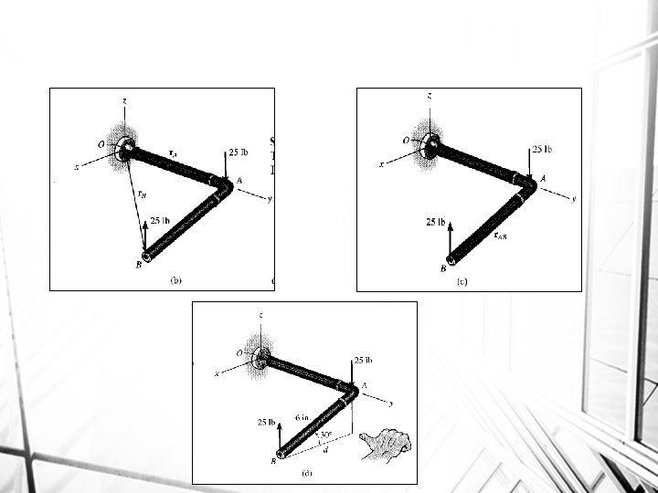
Example • Determine the couple moment acting on the pipe shown in Fig. 3. 24 a. Segment AB is directed 30 below the x-y plan
Solution I (vector analysis) The moment of the two couple forces can be found about any point. If point O is considered, Fig 3. 24 b, we have M = r. A x (-25 k) + r. B x (25 k) = (8 j) x (-25 k) + (6 cos 30 i + 8 j – 6 sin 30 k) x (25 k) = -200 i -129. 9 j + 200 i = {-130 j} lb. in It is easier to take moments of the couple forces about a point lying on the line of action of one of the forces, e. g. , point A, Fig. 3. 24 c. In this case the moment of the force A is zero, so that M = r. AB x (25 k) = (6 cos 30 i – 6 sin 30 k) x (25 k) = {-130 j} lb. in
Solution II(scalar analysis) Although this problem is shown in three dimensions, the geometry is simple enough to use the scalar equation M = Fd. The perpendicular distance between the lines of action of the forces is d = 6 cos 30° = 5. 20 in. , Fig. 3. 24 d. Hence, taking moments of the forces about either point A or B yields M = Fd. = 25 lb (5. 20 in) = 129. 9 lb. in Applying the right-hand rule, M acts in the –j direction. Thus, M = {130 j} lb. in
Resultant A force and couple system • When a rigid body is subjected to a system of forces and couple moments • The external effects on the body by replacing the system by an equivalent single resultant force acting at a specified point O and a resultant couple moment • Point O is not on the line of action of the forces, an equivalent effect is produced if the forces are moved to point O and the corresponding couple moments M 1=r 1 x. F 1 and M 2=r 2 x. F 2 are applied to body
AN EQUIVALENT SYSTEM (Section 4. 7) = • When a number of forces and couple moments are acting on a body, it is easier to understand their overall effect on the body if they are combined into a single force and couple moment having the same external effect • The two force and couple systems are called equivalent systems since they have the same external effect on the body.
MOVING A FORCE ON ITS LINE OF ACTION Moving a force from A to O, when both points are on the vectors’ line of action, does not change the external effect. Hence, a force vector is called a sliding vector. (But the internal effect of the force on the body does depend on where the force is applied).
MOVING A FORCE OFF OF ITS LINE OF ACTION Moving a force from point A to O (as shown above) requires creating an additional couple moment. Since this new couple moment is a “free” vector, it can be applied at any point P on the body.
FINDING THE RESULTANT OF A FORCE AND COUPLE SYSTEM • When several forces and couple moments act on a body, you can move each force and its associated couple moment to a common point O. • Now you can add all the forces and couple moments together and find one resultant force-couple moment pair.
Example 3. 5 • Replace the forces acting on the brace shown in Figure by an equivalent resultant and couple moment acting at point A.
+ FRx = Fx; FRx = -100 N - 400 cos 45 = - 382. 8 N = 382. 8 N + FRy = Fy; FRy = -600 N - 400 sin 45 = - 882. 8 N = 882. 8 N FR has a magnitude of and a direction of
• The resultant couple moment MRA is determined by summing the moments of the forces about point A. Assuming that positive moments act clockwise, we have + MRA = MA MRA = 100 N (0) + 600 N (0. 4 m) + (400 sin 45 ) (0. 8 m) + (400 cos 45 ) (0. 3 m) = 551 Nm
Example (Equivalent resultant force and couple moment) A structural member is subjected to a couple moment M and forces F 1 and F 2 as shown in Fig. below. Replace this system by an equivalent resultant force and couple moment acting at its base, point O.
The three-dimensional aspects of the problem can be simplified by using a Cartesian vector analysis. Expressing the forces and couple moment as Cartesian vectors, we have F 1 = {-800 k)N F 2 = (300 N)u. CB = (300 N) (rcb/rcb) = 300 [-0. 15 i+0. 1 j/ (0. 15)2 + (0. 1)2] = {-249. 6 i + 166. 4 j}N M = -500 (4/5)j + 500 (3/5)k = {-400 j + 300 k) Nm Force Summation FR = F; FR = F 1 + F 2 = -800 k – 249. 6 i + 166. 4 j = {-249. 6 i + 166. 4 j – 800 k} N
Moment Summation MRO = MC + MO MRO = M + r. C x F 1 + r. B x F 2 MRO = (-400 j + 300 k) + (1 k) x (-800 k) + i j k -0. 15 0. 1 1 - 249. 6 166. 4 0 = (-400 j + 300 k) + (0) + (-166. 4 i – 249. 6 j) = {-166 i -650 j + 300 k} Nm
Exercise 3: Replace three forces shown with an equivalent force-couple system at A. F 1 F 2 F 3
To find the equivalent set of forces at A.
Find the moments about point A. Using the line of action for the force at B. The force can be moved along the line of action until it reaches perpendicular distance from A
Find the moments about point A. The force at O can be broken up into its two components in the x and y direction Using the line of action for each component, their moment contribution can be determined.
Find the moments about point A. Using the line of action for Fx component d is 160 mm. Fy component is 0 since in line with A.
The final result is R = 585 N at 70. 0 o M = 132 Nm