UNIT IV BOLTED JOINTS BOLTED JOINTS Threaded Joint

UNIT IV BOLTED JOINTS
 Screwed Joint • Threaded joint is defined as a")
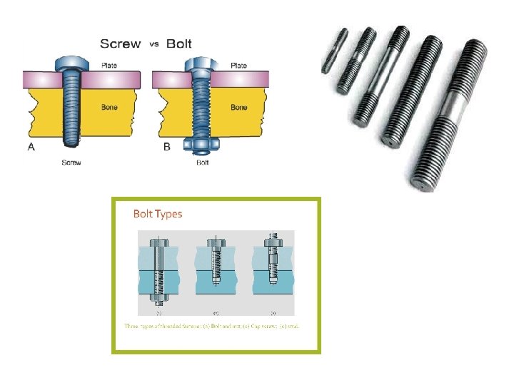
BOLTED JOINTS Threaded Joint (Or) Screwed Joint • Threaded joint is defined as a separable joint of two or more machine parts that are held together by means of a threaded fastening such as a bolt and a nut. • APPLICATION Threaded joints are used to hold two or more machine parts together. These parts can be dismantled, if required, without any damage to machine parts or fastening.
 Screwed Joint ADVANTAGES : 1. Highly reliable 2. Convenient")
BOLTED JOINTS Threaded Joint (Or) Screwed Joint ADVANTAGES : 1. Highly reliable 2. Convenient to assemble and disassemble 3. Compact construction 4. Can be placed in any position 5. High Accuracy DISADVANTAGES : 1. Stress concentration in the threaded portions 2. Loosen when subjected to vibrations 3. Cost of tightening screw is more in manual assembly
 SCREW")
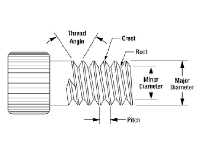
TERMINOLOGY OF BOLT (OR) SCREW

TERMINOLOGY OF SCREW THREADS

FORMS OF SCREW THREADS

BOLT OF UNIFORM STRENGTH The ideal bolt is one, which is subjected to same stress level at different cross-sections i. e the entire bolt is stressed to same limiting value, resulting in maximum energy absorption It is called BOLT OF UNIFORM STRENGTH

Methods To Obtain Bolt Of Uniform Strength 1. Reduce the shank diameter to core diameter of threads or even less. 2. Reduce the cross-sectional area of the shank is by drilling a hole.

To Reduce The Cross-sectional Area Of The Shank By Drilling A Hole.

Stresses in Screwed Fastening due to Static Loading 1. Internal stresses due to screwing up forces 2. Stresses due to external forces 3. Stress due to combination of internal stresses and external forces.

Internal Stresses Due To Screwing Up Forces 1 Tensile stresses due to stretching of bolt 2 Torsional shear stress caused by frictional resistance of threads during tightening 3 Shear stress across the threads 4 Compression or crushing stress on thread 5 Bending stress if surfaces under the head or nut are not perfectly parallel to the bolt axis

INITIAL STRESSES DUE TO SCREWING UP FORCES 1 Tensile stress due to stretching of bolt. • Pi = 2840 d for leak proof joint • Pi = 1420 d for ordinary joint Pi = Initial tension in a bolt, d = Nominal diameter of bolt, in mm. If bolt is not initially stressed, Maximum safe axial load is given by P = Stress area X Cross sectional area at bottom of thread

2 Torsional shear stress caused by frictional resistance of threads during tightening 3 Shear stress across the threads

4 Compression or crushing stress on thread 5 Bending stress if surfaces under the head or nut are not perfectly parallel to the bolt axis

Stresses Due To External Forces 1 Tensile stresses 2 Shear stress across the threads 3 Combined tension and shear stress

STRESSES DUE TO EXTERNAL FORCES 1 Tensile stresses 2 Shear stress across the threads

3 Combined tension and shear stress STRESSES DUE TO COMBINED FORCES
 Design Of Bolts Or Studs B) Design Of Cylinder")
Design of Cylinder Covers A) Design Of Bolts Or Studs B) Design Of Cylinder Cover Plate C) Design Of Cylinder Flange
 Design of bolts or studs")
A) Design of bolts or studs

OUTSIDE DIAMETER OF COVER d 1 the diameter of hole for bolt or stud
 Design Of Cylinder Cover Plate")
B) Design Of Cylinder Cover Plate
 Design Of Cylinder Flange")
C) Design Of Cylinder Flange

ECCENTRICALLY LOADED BOLTED JOINTS PRIMARY SHEAR FORCE SECONDARY SHEAR FORCE ASSUME

ECCENTRICALLY LOADED BOLTED JOINTS A BOLT WITH SMALL ANGLE BETWEEN THE FORCES IS SUBJETCED TO MAXIMUM FORCE RESULTANT LOAD: : ASSUMPTIONS: COMPONENTS CONNECTED BY BOLTS ARE RIGID BOLTS HAVE SAME CROSS SECTIONAL AREA

ECCENTRICALLY LOAD PERPENDICUALR TO AXIS OF BOLT DIRECT SHEAR FORCE MOMENT ASSUME

A BOLT LOCATED AT FARTHEST DISTANCE FROM TILTING EDGE IS SUBJETCED TO MAXIMUM FORCE SHEAR FORCE TENSILE FORCE ASSUMPTIONS: :

ECCENTRICALL LOAD PARALLEL TO AXIS OF BOLT DIRECT TENSILE FORCE DUE TO TILT ASSUME

A BOLT LOCATED AT FARTHEST DISTANCE FROM TILTING EDGE IS SUBJETCED TO MAXIMUM FORCE DIRECT TENSILE FORCE DUE TO TILT RESULTANT LOAD: : ASSUMPTIONS: :
- Slides: 32