Lecture 3 Topics IEEE 754 Floating Point Binary

Lecture 3 • Topics – IEEE 754 Floating Point – Binary Codes • • • BCD ASCII, Unicode Gray Code 7 -Segment Code M-out-of-n codes – Serial line codes 1

Floating Point Numbers

Floating Point • Need to represent “real” numbers • Fixed point too restrictive for precision and range • Not unlike familiar “scientific notation” + 6. 022 x 1023 Sign Mantissa Exponent Normalized mantissa – single digit to left of decimal point 3

IEEE 754 Floating Point Standard Sign Binary + 1. 101011 x 212 Sign Mantissa Exponent Significand Exponent A normalized (binary) mantissa will always have a leading 1 so we can assume it and get an extra bit of precision instead 1 Fraction Exponents are stored with a bias which is added to the exponent before being stored (allows fast magnitude compare) Universally used on virtually all computers Several levels of precision/range: Single, Double-Extended 4

Floating-Point Standards • The IEEE has established a standard for floatingpoint numbers • The IEEE-754 single precision floating point standard uses an 8 -bit exponent (with a bias of 127) and a 23 -bit significand. • The IEEE-754 double precision standard uses an 11 -bit exponent (with a bias of 1023) and a 52 -bit significand.

IEEE 754 Single Precision Floating Point Standard

IEEE 754 Floating Point Standard • Single Precision – 32 bits, Bias = 127 1 8 23 ± Exponent + Bias 31 30 Observe that here we have Exponent plus BIAS Significand 0 23 22 F = -1 Sign x (1+Significand) x 2(Exponent-Bias) 7

IEEE 754 Floating Point Standard Hidden 1 • Example 1 F = -1 Sign x (1+Significand) x 2(Exponent-Bias) 8 Remember to add 1 1 10000001 31 30 - 129 23 0100000000000 23 22 = - 1. 012 x 2(129 -127) = - 1. 25 x 22 = - 1. 25 x 4 = - 5. 0 0 = 0. 2510 = - 1. 012 x 2(129 -127) = - 1. 012 x 22 = - 1012 = - 5. 0 8

IEEE 754 Floating Point Standard • Will commonly see these expressed as hex 1 8 23 1 10000001 31 30 23 22 8+4 0100000000000 0 8+2 C 0 A 00000 1010 A 1011 B 1100 C 10 = A 11 = B 12 = C 13 = D 14 = E 15 = F

Example of calculation of Floating-Point Representation • Example: Express -3. 75 as a floating point number using IEEE single precision. • First, let’s normalize according to IEEE rules: – 3. 75 = -11. 112 = -1. 111 x 21 – The bias is 127, so we add 127 + 1 = 128 (this is our final exponent+bias) – The first 1 in the significand is implied, so we have: (implied) – Since we have an implied 1 in the significand, this equates to -(1). 1112 x 2 (128 – 127) = -1. 1112 x 21 = -11. 112 = -3. 75. F = -1 Sign x (1+Significand) x 2(Exponent-Bias) verification

FP Ranges • For a 32 bit number – 8 bit exponent – +/- 2256 1. 5 x 1077 • Accuracy – The effect of changing lsb of significand – 23 bit significand 2 -23 1. 2 x 10 -7 – About 6 decimal places

IEEE 754 Floating Point Standard: SPECIAL CASES: Zeros, Infinities, Denormalized

Expressible Numbers in two typical 32 -bit formats

Representation of Floating Point Numbers • IEEE 754 single precision 31 30 Sign 23 22 Biased exponent 0 Normalized Mantissa (fraction, significand) (implicit 24 th bit = 1) Zero (-1)s fraction 2 E-127 1+Significand Not a Number

IEEE 754 Floating Point Standard • Some Special Cases – Zero (no assumed leading 1) • Exponent = 0, Significand = 0 – Na. N (Not a Number), e. g. ¥ • Exponent = 255 X = -1 S 2 -126 (0. fraction) – Denormalized (Subnormal) numbers Subnormal • Exponent = 0, Significand 0 Standard FP number F = -1 Sign x (1+Significand) x 2(Exponent-Bias) Bias = 127 Remember to subtract bias

Special-case numbers: Zeros and Infinities Zeros • Zeroes: 0 00… 0 1 00… 0 +0 -0 • Infinities: 0 11… 1 00… 0 1 11… 1 00… 0 +∞ -∞

Zeros • How do you represent 0? – Sign = ? , Exponent = ? , Significand = ? • Here’s where the hidden “ 1” comes back to bite you “ 1” • Hint: Zero is small. What’s the smallest number you can generate? – Exponent = -127, Significand = 1. 0 – -10 (1. 0) x 2 -127 = 5. 87747 x 10 -39 • IEEE Convention – When E = 0 (Exponent = -127), we’ll interpret numbers differently… • 0 000000000000000 = 0 not 1. 0 x 2 -127 • 1 0000000000000000 = -0 not -1. 0 x 2 -127 • • Yes, there are “ 2” zeros. Setting E=0 is also used to represent a few other small numbers besides 0. In all of these numbers there is no “hidden” one assumed in F, and they are called the “unnormalized (denormalized) numbers”. WARNING: be careful !

Positive Infinity, Negative Infinity and Not a Number • IEEE floating point also reserves the largest possible exponent to represent “unrepresentable” large numbers – Positive Infinity: S = 0, E = 255, F = 0 Infinity • 0 1111 000000000000 = +∞ • 0 x 7 f 800000 – Negative Infinity: S = 1, E = 255, F = 0 Infinity • 1 1111 000000000000 = -∞ • 0 xff 800000 – Other numbers with E = 255 (F ≠ 0) are used to represent exceptions or Not-A-Number (NAN) Not-A-Number – It does, however, attempt to handle a few special cases.

Special Values Infinities and NANs • Condition for infinity and Na. N – exp = 111… 1 • Cases – INFINITY Not a Number (Na. N): E = 11… 1; F != 00… 0 • exp = 111… 1, frac = 000… 0 • Represents value (infinity) infinity • Operation that overflows • Both positive and negative • E. g. , 1. 0/0. 0 = 1. 0/ 0. 0 = + , 1. 0/ 0. 0 = , log(0) = - ∞ – NOT A NUMBER (Na. N) • exp = 111… 1, frac 000… 0 • Represents case when no numeric value can be determined • E. g. , sqrt(– 1), , √-1, -∞ x 42, 0/0, ∞/∞, log(-5)
 numbers")
IEEE 754 Floating Point Standard: subnormal (denormalized) numbers

Property of IEEE 754 Floating Point Standard: Let us analyze the low-End of the IEEE Spectrum 0 denorm gap 2 -bias 21 -bias 22 -bias normal numbers with hidden bit start from here up Distance from zero to smallest positive number is 1. 000000000001 x 2 -127 ~= 2 -127 Distance to next number is 0. 000000000001 x 2 -127 = 2 -23 x 2 -127 = 2 -150 FP numbers S Exponent Significand 1 8 23 0 0 000000000000000000000001 00000000000000010 0000000000000011 00000000000000100 =0 = 1. 000000000001 x 2 -127 = 1. 0000000000010 x 2 -127 = 1. 0000000000011 x 2 -127 = 1. 0000000000100 x 2 -127

The Denormalized Gap in the IEEE Spectrum 0 denorm gap 2 -bias 21 -bias 22 -bias normal numbers with hidden bit start from here up • “Denormalized Gap” – As we see above, the gap between 0 and the next representable normalized number is much larger than the gaps between nearby representable numbers – Addresses gap caused by implicit leading 1 gap – IEEE standard uses denormalized numbers to fill in the gap, making the distances between numbers near 0 more alike • Denormalized numbers have a hidden “ 0” and… • … a fixed exponent of -126 • X = -1 S 2 -126 (0. fraction) Denormalized number • Zero is represented using 0 for the exponent and 0 for the mantissa (fraction). • Either, +0 or -0 can be represented, based on the sign bit.

Denormalized numbers to represent very small numbers E = 00… 0 Different interpretation applies denormalized numbers Fraction or mantissa For standard FP • Smallest positive number in FP standard (a) is 1. 000… 000 x 2 -126 • Next number in FP standard (b) is 1. 000… 001 x 2 -126 = (2 -126 + 2 -149) • Subnormal Numbers - properties – Implicit Exponent of -126 – F = -1 Sign x (Significand) x 2(-126) – Smallest positive number in subnormal is (a) = 0. 000… 001 x 2 -126 = 2 -149 – Next smallest number in subnormal is (b) = 0. 000… 010 x 2 -126 = 2 -148 X = -1 S 2 -126 (0. fraction)
 numbers to represent very small numbers X = -1 S 2 -126")
Denormalized (subnormal) numbers to represent very small numbers X = -1 S 2 -126 (0. fraction) • Subnormal Numbers - properties – Implicit Exponent of -126 – F = -1 Sign x (Significand) x 2(-126) – Smallest positive number in subnormal is (a) = 0. 000… 001 x 2 -126 = 2 -149 – Next smallest number in subnormal is (b) = 0. 000… 010 x 2 -126 = 2 -148 • Denormalized numbers have no hidden 1 • Denormalized numbers allow numbers very close to 0 • Denormalization rule: number represented is (-1)S× 0. fraction× 2 -126 (singleprecision) (-1)S× 0. fraction× 2 -1022 (doubleprecision) • Note: zeroes follow this rule Fraction or mantissa
S× 0. fraction×")
Denormalized Values • Condition – exp = 000… 0 • Value (-1)S× 0. fraction× 2 -127+1= -126 (single-precision) – Exponent value E = –Bias + 1 – Significand value M = 0. xxx…x 2 • xxx…x: bits of frac • Cases – exp = 000… 0, frac = 000… 0 • Represents value 0 • Note that have distinct values +0 and – 0 – exp = 000… 0, frac 000… 0 • Numbers very close to 0. 0 • Lose precision as get smaller • “Gradual underflow” Object Represented

Subnormal Numbers - properties Exponent always zero • Implicit Exponent of -126 2 -23 • F = -1 Sign x (Significand) x 2(-126) • Smallest positive number (a) = 0. 000… 001 x 2 -126 = 2 -149 • Next smallest number (b) = 0. 000… 010 x 2 -126 = 2 -148 For comparison for FP number F = -1 Sign x (1+Significand) x 2(Exponent-Bias) Bias = 127 26

Summary of Floating Point Real Number Encodings -Normalized -Denorm Na. N +Denorm +Normalized + 0 +0 Na. N

Tiny examples for better explanation

Tiny Floating Point Example in IEEE Format 7 6 s exp 3 2 0 frac • 8 -bit Floating Point Representation – the sign bit is in the most significant bit. – the next four bits are the exponent, with a bias of 7. – the last three bits are the frac l. Same General Form as IEEE Format – normalized, denormalized – representation of 0, Na. N, infinity

Values Related to the Exponent 1 -6 2 -7 3 -7 4 -7 7 -7 8 -7 Exp exp E 2 E 0 1 2 3 4 5 6 7 8 9 10 11 12 13 14 15 0000 0001 0010 0011 0100 0101 0110 0111 1000 1001 1010 1011 1100 1101 1110 1111 -6 -6 -5 -4 -3 -2 -1 0 +1 +2 +3 +4 +5 +6 +7 n/a 1/64 1/32 1/16 1/8 1/4 1/2 1 2 4 8 16 32 64 128 (denorms) exp = 4 exponent bits f = 3 fraction bits Bias is 7 (inf, Na. N) F = -1 Sign x (1+Significand) x 2(Exponent-Bias) bias of 7

Dynamic Range E Value 0000 001 0000 010 -6 -6 -6 0 1/8*1/64 = 1/512 2/8*1/64 = 2/512 0000 0001 110 111 000 001 -6 -6 6/8*1/64 7/8*1/64 8/8*1/64 9/8*1/64 = = 6/512 7/512 8/512 9/512 0110 0111 110 111 000 001 010 -1 -1 0 0 0 14/8*1/2 15/8*1/2 8/8*1 9/8*1 10/8*1 = = = 14/16 15/16 1 9/8 10/8 7 7 n/a 14/8*128 = 224 15/8*128 = 240 inf s exp 0 0 Denormalized 0 … numbers 0 0 … 0 0 Normalized 0 numbers 0 0 … 0 0 0 frac 1110 1111 000 closest to zero largest denorm smallest norm closest to 1 below closest to 1 above largest norm
 – e = 3")
Distribution of Values • 6 -bit IEEE-like format (another example) – e = 3 exponent bits – f = 2 fraction bits – Bias is 3 • Notice how the distribution gets denser toward zero.
 • 6 -bit IEEE-like format – e = 3")
Distribution of Values (close-up view) • 6 -bit IEEE-like format – e = 3 exponent bits – f = 2 fraction bits – Bias is 3

Interesting Numbers: comparison of single precision and double precision • Description • Zero • Smallest Positive Denorm. exp 00… 00 frac 00… 00 00… 01 Numeric Value 0. 0 2– {23, 52} X 2– {126, 1022} • Largest Denormalized 00… 00 11… 11 (1. 0 – ) X 2– {126, 1022} • Smallest Positive Normalized 00… 01 00… 00 1. 0 X 2– {126, 1022} • One • Largest Normalized 01… 11 11… 10 00… 00 11… 11 1. 0 (2. 0 – ) X 2{127, 1023} – Single 1. 4 X 10– 45 – Double 4. 9 X 10– 324 – Single 1. 18 X 10– 38 – Double 2. 2 X 10– 308 – Just larger than largest denormalized – Single 3. 4 X 1038 – Double 1. 8 X 10308

OTHER IEEE 754 Floating Point Standards

Floating-Point Representation • In both the IEEE single-precision and doubleprecision floating-point standard, standard the significant has an implied 1 to the LEFT of the radix point. – The format for a significand using the IEEE format is: 1. xxx… – For example, 4. 5 =. 1001 x 23 in IEEE format is 4. 5 = 1. 001 x 22. • The 1 is implied, which means is does not need to be listed in the significand (the significand would include only 001).
 Single precision (binary 32)")
Four IEEE 754 Formats Exponent +bias Half precision (binary 16) Single precision (binary 32) Double precision (binary 64) Quadruple precision (binary 128) 37

Single-Precision Range • Exponents 0000 and 1111 reserved • Smallest value – Exponent: 00000001 actual exponent = 1 – 127 = – 126 – Fraction: 000… 00 significand = 1. 0 – ± 1. 0 × 2– 126 ≈ ± 1. 2 × 10– 38 • Largest value – exponent: 11111110 actual exponent = 254 – 127 = +127 – Fraction: 111… 11 significand ≈ 2. 0 – ± 2. 0 × 2+127 ≈ ± 3. 4 × 10+38

IEEE Double precision standard 1 S 11 E 52 fraction • E not 00… 0 (decimal 0) or 11… 1(decimal 2047) • Normalized rule: number represented is (-1)S× 1. fraction× 2 E-1023 For comparison F = -1 Sign x (1+Significand) x 2(Exponent-Bias) Bias = 127

Double-Precision Range • Exponents 0000… 00 and 1111… 11 reserved • Smallest value – Exponent: 000001 actual exponent = 1 – 1023 = – 1022 – Fraction: 000… 00 significand = 1. 0 – ± 1. 0 × 2– 1022 ≈ ± 2. 2 × 10– 308 • Largest value – Exponent: 111110 actual exponent = 2046 – 1023 = +1023 – Fraction: 111… 11 significand ≈ 2. 0 – ± 2. 0 × 2+1023 ≈ ± 1. 8 × 10+308

41

Other Formats: bias calculated from number of bits in the exponent X 86 Extended precision (80 bits) How to calculate the bias? Bias Used in 8087 Math co-processor and subsequently in all x 86 hardware floating point (intermediate operations). Note explicit J-bit 2(5 -1) – 1 = 24 -1 = 15 42
 5")
Other IEEE 754 Formats: calculating bias for each case Half precision (binary 16) 5 bits in exponent so bias is 15 according to table 8 bits in exponent so bias is 127 according to table Single precision (binary 32) Double precision (binary 64) Quadruple precision (binary 128) 11 bits in exponent so bias is 1023 according to table We use this table to calculate bias 15 bits in exponent so bias is 16383 according to table No explicit bias = 127 in these formats
")
Interesting topics about floating point (not for exams)

Floating point AIN’T NATURAL • It is CRUCIAL for computer scientists to know that Floating Point arithmetic is NOT the arithmetic you learned since childhood • 1. 0 is NOT EQUAL to 10*0. 1 (Why? ) 1. 0 is NOT EQUAL to 10*0. 1 – 1. 0 * 10. 0 == – 0. 1 * 10. 0 != 1. 0 != – 0. 1 decimal == 1/16 + 1/32 + 1/256 + 1/512 + 1/4096 + … == • 0. 0 0011 0011 … – In decimal 1/3 is a repeating fraction 0. 333333… – If you quit at some fixed number of digits, then 3 * 1/3 != 1 • Floating Point arithmetic IS NOT associative – x + (y + z) is not necessarily equal to (x + y) + z • Addition may not even result in a change Addition may not – (x + 1) MAY == x
 –")
Floating Point Disasters - Ariane 5 • $7 B Rocket crashes (Ariane 5) – When the first ESA Ariane 5 was launched on June 4, 1996, it lasted only 39 seconds, then the rocket veered off course and self-destructed. – Cargo worth $500 million http: //www. around. com/ariane. html • Why – Computed horizontal velocity as floating point number • An inertial system, produced a floating-point exception while trying to convert a 64 -bit floating-point number to an integer. – Converted to 16 -bit integer – Worked OK for Ariane 4 – Overflowed for Ariane 5 • Used same software • For Ariane 5 larger values were generated

Floating Point Disasters • Scud Missiles get through, 28 die – In 1991, during the 1 st Gulf War, a Patriot missile defense system let a Scud get through, hit a barracks, and kill 28 people. The problem was due to a floating-point error when taking the difference of a converted & scaled integer. (Source: Robert Skeel, "Round-off error cripples Patriot Missile", SIAM News, July 1992. ) • Intel Ships and Denies Bugs – In 1994, Intel shipped its first Pentium processors with a floating-point divide bug. The bug was due to bad look-up tables used to speed up quotient calculations. After months of denials, Intel adopted a no-questions replacement policy, costing $300 M. (http: //www. intel. com/support/processors/pentium/fdiv/)

Floating-Point Multiplication S E F S F × Small ADDER Subtract 127 E 24 by 24 Control round Add 1 Mux (Shift Right by 1) S E F Step 1: Multiply significands Add exponents ER = E 1 + E 2 -127 (do not need twice the bias) Step 2: Normalize result (Result of [1, 2) *[1. 2) = [1, 4) at most we shift right one bit, and fix exponent Do not worry about the details as for now

Floating-Point Addition Do not worry about the details as for now

MIPS Floating Point • Floating point “Co-processor” – 32 Floating point registers • separate from 32 general purpose registers • 32 bits wide each • use an even-odd pair for double precision • Instructions: – – – – add. d fd, fs, ft # fd = fs + ft in double precision add. s fd, fs, ft # fd = fs + ft in single precision sub. d, sub. s, mul. d, mul. s, div. d, div. s, abs. d, abs. s l. d fd, address # load a double from address l. s, s. d, s. s Conversion instructions Compare instructions Branch (bc 1 t, bc 1 f)
")
BCD (Binary Coded Decimal)
 • Used in early 4 -bit m. P • Simple")
BCD (Binary Coded Decimal) • Used in early 4 -bit m. P • Simple displays • 4 Bits/Decimal Digit 2 5 52

ASCII numbers
 • For encoding")
ASCII • American Standard Code for Information Interchange (pronounced: As’ key) • For encoding text • Universally used – EBCDIC (old IBM mainframe standard) died – Unicode for international (non-Roman) languages • UTF-8 • UTF-16 • UTF-32 8 -bit variable width encoding (1 -4 bytes) 16 -bit variable width encoding 32 -bit fixed width encoding • UTF-8 commonly used for HTML/web browsers, Free. BSD, Linux • Gcc uses UTF-32 54

“ECE 171” E C E 1 7 1 1000101 1000011 1000101 0110001 0110111 0110001 0000000 As a string of characters

56

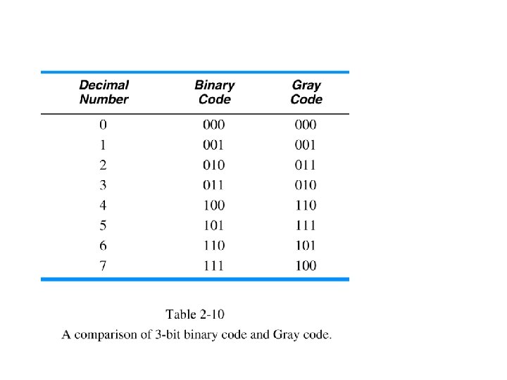
Gray Code
. Mechanical Sensors. • Adjacent codes differ by single bit –")
Reflective Gray Code (RGC). Mechanical Sensors. • Adjacent codes differ by single bit – “Unit Distance Code” • Often used in interfacing mechanical sensors Shaft position 58

• This is not Gray code. • More than one bit changes at a time

Reflective Gray Code 61

First bit the same: A=a abc ABC Note that this bit is 1 when first two bits in binary code are different B=a b

abc ABC Note that this bit is 1 when the second and third bits in binary code are different C=b c
 64")
Reflective Gray Code (Conversion) 64
 65")
Reflective Gray Code (Conversion) 65

7 -Segment Code 66
 8 devices 23 = 8 With binary coded device")
1 -out-of-n codes (1 -hot) 8 devices 23 = 8 With binary coded device selection 000 001 111 therefore 3 bits (wires) suffice… if devoted 8 wires… used in SCSI disk drives, PCI enumeration With 1 -hot coded device selection 67

Hypercubes
 for n=1, 2, 3, and 4.")
Hypercubes (n-cubes) for n=1, 2, 3, and 4.

Traversing n-cubes in Gray-code order

Hypercubes for codes

Using Hypercubes to design error-detecting and error-correcting codes.

Even-parity Codes and Odd-parity Codes

Using Hypercubes to Minimize Boolean Functions abc’ abc ab a’bc ac ab’c a’b’c’ F= ab+bc+ac+a’b’c’ bc

Hamming Distance 1 from center 0001011001 1010010 Hamming Distance 3 of codewords Hamming Distance 1 from centerv center • We have 3 codewords on 7 positions. • Their Hamming distance is 3

See next slide Natural binary order


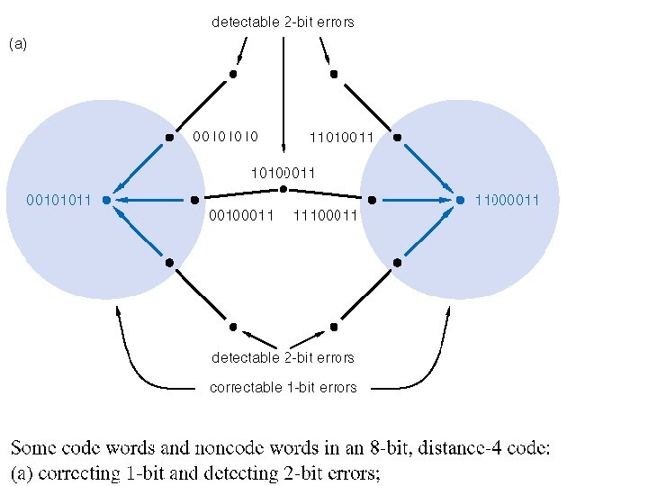
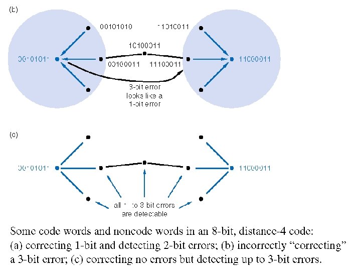
Error Detection and Correction

Error Detection and Correction • Errors occur during data storage/retrieval and transmission • Noise, cross-talk, EMI, cosmic rays, impurities in IC materials • More common with high speeds, lower voltages • Use m-out-of-n codes to detect errors • Not all possible codes are used (valid) • Errors in used (valid) codes (hopefully) produce unused (invalid) codes

Example of Error Detection and Correction • Example: Luhn Algorithm • Credit cards, IMEI (International Mobile Equipment Identity) • Start from right, double every second digit • Add all digits • Add a final check digit to ensure sum is multiple of 10 82

Serial Data Transmission & Storage

Serial Data Transmission & Storage Serial • Parallel Low Voltage Differential Signaling – Storage: each bit of word read/written simultaneously Storage – Transmission: each bit has separate signal path Transmission • Serial – Reduce costs – Simplify design – Higher speed (LVDS, skew) • Applications – USB – PCI Express 84
 85")
Universal Serial Bus (USB) 85

PCI Express 86

Serial Data Transmission & Storage • Clock – Determines rate at which bits are transmitted (“bit rate”) – “bit time”= clock period (1/bit rate) = “bit cell” • Sync – Determines start of byte (or packet) • Data Format – Determined by “line code” 87

Codes for Serial Data Transmission and Storage – NRZ and NRZI • • NRZ – Non Return to Zero NRZI – Non Return to Zero Invert (on ones) NRZI – – Transition based Differential signaling: USB Toggles on ones • • • Does not toggle on zeros NRZI is a transition based code disk drives store don’t store 0 s/1 s but adjacent places may have different/same flux as neighbor, LVDS applications May need/want to explain source synchronous vs. embedded clocks and clock recovery Low Voltage Differential Signaling 88

Codes for Serial Data Transmission and Storage – RZ, BPRZ and Manchester • RZ – Return to Zero • BPRZ – Bipolar Return to Zero • • – “DC balanced” – MLT-3 (100 Base T Ethernet) Manchester encoding – Guarantees a transition in every bit cell – Facilitates clock recovery – Requires higher bandwidth – Original coax-based 10 Mbps Ethernet Other techniques for DC balancing (and edge density) – m-out-of-n-codes (e. g. 8 B 10 B): m-out-of-n-codes Gigbabit Ethernet Returns to zero after every “one” of data Transition from 1 to 0 for ones Transition from 0 to 1 for zeros 89

Why Serial? “Parallel” Device A “Serial” Device B 10 bidirectional wires at 250 Mbps Device A + + - Device B pair unidirectional wires at 2500 Mbps (2. 5 Gbps) 90

Traditional Parallel Bus Device A Device B Same clock • • Traditional Parallel Bus is used in low to medium 100 MHz range • • It has some issues – Board trace length has an effect on skew – There is a clock skew across devices Because clock is distributed to both sender and receiver, its arrival time at sender and receiver is not simultaneous. Therefore there will be a skew with respect to the sent or received data. 91

Traditional Parallel Bus Device A Device B • Issues – Faster data rate squeezes “eye” • Does everyone know what’s meant by “eye” • – it’s the window during which data is expected to be valid. • “Guardband” is test term which refers to the necessary “safety”, closing the eye. • This is an issue in system performance, error rates, and of course in testing. 92

Source Synchronous Bus Clock goes with data when we transmit from B to A Device B • Used in 200 MHz to 1. 6 GHz range • Clock signal is “forwarded” with data • Design impact of Source Synchronous Bus: 1. Board layout track length mismatch still adds to skew 2. Eliminates skew error term caused by clock domain skew 3. Allows faster cycle times than parallel 93

Embedded Clock Data Clock signal embedded with data • Clock signal is “embedded” with data – Received used digital phase locked loop (DPLL) to “recover” clock and determine where bit times are recover” clock – Edge density must be guaranteed by encoding scheme • Examples – PCI Express, USB, Serial Rapid. IO, Infiniband – Intel’s new Quick. Path Interconnect We’ll look at the encoding scheme which ensures this in a moment 94
 Device A Device B Device A sends pulse train")
Edge Lock Technique (Tracking Receiver) Device A Device B Device A sends pulse train to Device B “locks” onto edges to be in sync with pulse stream In order to achieve locking and clock recovery we need to ensure a certain density of edge transitions – this is where the encoding scheme comes in… 95

Ensuring Edge Density: m-of-n codes • Some 8 -bit code words have too few 1 s (or 0 s) to ensure edge density sufficient to recover clock • 8 b 10 encoding (developed by IBM in 1983) – Use 10 -bit code words, but only use a subset of the available 210 code words • No more than five 0 s or 1 s in a row • Balanced number of 0 s and 1 s (difference between count of 0 s and 1 s in a string of at least 20 bits is no more than two. – Benefits • Ensure edge density • Avoid DC bias at receiver from imbalance – Running disparity for unbalanced codewords 8 bit byte 10 bit code – 256 data characters • All 8 -bit bytes • 12 control characters (INIT, etc) Table lookup Device A Device B Parallel Data TX FIFO 8 B/10 B Serializer Encoder + _ Parallel Data RX FIFO 8 B/10 B Deserializer Decoder + _ Deserializer 8 B/10 B Decoder RX FIFO Parallel Data Serializer 8 B/10 B Encoder TX FIFO Parallel Data 96

1. 2. 3. 4. 5. 6. 7. 8. 9. Questions, Problems and EXAM Problems (1) What is a floating point number? Explain the IEEE 754 Floating Point Standard What are subnormal numbers? Give examples of several IEEE 754 formats Convert number 25310 to BCD code. Convert number 01010011012 to BCD code. Why do you think BCD code was invented? What are the origins of Gray code? Encode your first name in ASCI code. 97
 Questions, Problems and EXAM Problems (2) 10. Draw an equivalent")
Questions and Problems (2) Questions, Problems and EXAM Problems (2) 10. Draw an equivalent of the mechanical device from slide “Reflective Gray Code (RGC). Mechanical Sensors” that will have 16 sections. What will be accuracy of the angle detected by this device. 11. How would you use this mechanical device in a robot? 12. Create a table specifying conversion from natural binary code to 7 -segment code. 13. Create a table that will specify the conversion from natural binary code to 1 -hot code. 14. Create a table that will specify the conversion from some maximal number of natural binary codewords to two-out-of-4 code. 98
 Questions, Problems and EXAM Problems (3) 15. What are the")
Questions and Problems (3) Questions, Problems and EXAM Problems (3) 15. What are the advantages of 1 -out-of-n and 2 -out-of-n codes? 16. What do you know about USB bus? 17. What do you know about PCI Express? 18. Explain Serial Data Transmission concept. 19. Compare serial and parallel data transmission. 20. Encode 0011010111 in NRZ code. 21. Encode 0011010111 in NRZI code. 22. Encode 0011010111 in NRZ code. 23. Encode 0011010111 in RZ code. 24. Encode 0011010111 in BPRZ code. 25. Encode 0011010111 in Manchester code. 99
 Questions, Problems and EXAM Problems (4) 26. Explain the concept")
Questions and Problems (4) Questions, Problems and EXAM Problems (4) 26. Explain the concept of Source Synchronous 27. Explain the concept of Embedded Clock Bus. the concept of 28. Explain the concept of Edge Lock Technique the concept of 29. Why m-of-n codes ensure Edge Density? codes e 30. Explain two examples of error-detecting codes. 31. What is Differential Signaling? 32. Low Voltage Differential Signaling 33. What is LVDS? 100
 Questions, Problems and EXAM Problems (5) 34. Explain the concept")
Questions and Problems (5) Questions, Problems and EXAM Problems (5) 34. Explain the concept of Source Synchronous 35. Explain the concept of Embedded Clock Bus. the concept of 36. Explain the concept of Edge Lock Technique the concept of 37. Why m-of-n codes ensure Edge Density? codes e 38. Explain two examples of error-detecting codes. 39. What is Differential Signaling? 40. Low Voltage Differential Signaling 41. What function is represented in the hypercube in the right? 101
 Questions, Problems and EXAM F = -1 x (1+Significand) x")
Questions and Problems (6) Questions, Problems and EXAM F = -1 x (1+Significand) x 2 Problems (6) Sign (Exponent-Bias) • 42. Represent Positive One in single precision – Sign = +, Exponent = 0, Significand = 1. 0 • 1 = -10 (1. 0) x 20 • S = 0, E = 0 + 127, F = 1. 0 – ‘ 1’ • 0 01111111 000000000000 = 0 x 3 f 800000 • 43. Represent One-half in single precision – Sign = +, Exponent = -1, Significand = 1. 0 • ½ = -10 (1. 0) x 2 -1 • S = 0, E = -1 + 127, F = 1. 0 – ‘ 1’ • 0 01111110 000000000000 = 0 x 3 f 000000 • 44. Represent Minus Two in single precision E = +1 + 127=128 – Sign = -, Exponent = 1, Significand = 1. 0 • -2 = -11 (1. 0) x 21 • 1 1000000000000 = 0 xc 0000000 • 45. Your task is to represent -1, -1/2 and 2 in single precision
 Questions and Problems (7) 46. Represent 0. 75")
Questions, Problems and EXAM Problems (7) Questions and Problems (7) 46. Represent 0. 75 as a floating point number in single precision 0. 75 ten = 0. 11 two = 1. 1 x 2 -1 1. 1 = 1. fraction → fraction = 1 E – 127 = -1 → E = 127 -1 = 126 = 01111110 two S = 0 001111110100000000000 = 0 x 3 F 400000

Sources Prof. Mark G. Faust John Wakerly Internet Jeremy R. Johnson Anatole D. Ruslanov William M. Mongan
- Slides: 104