Introduction to Energy Engineering Lecture 2 Electrical Energy


- Slides: 81
Introduction to Energy Engineering Lecture 2 Electrical Energy Generation Dr Mike Spann School of EECE m. spann@bham. ac. uk
Part I The Fundamentals of Electricity Generation
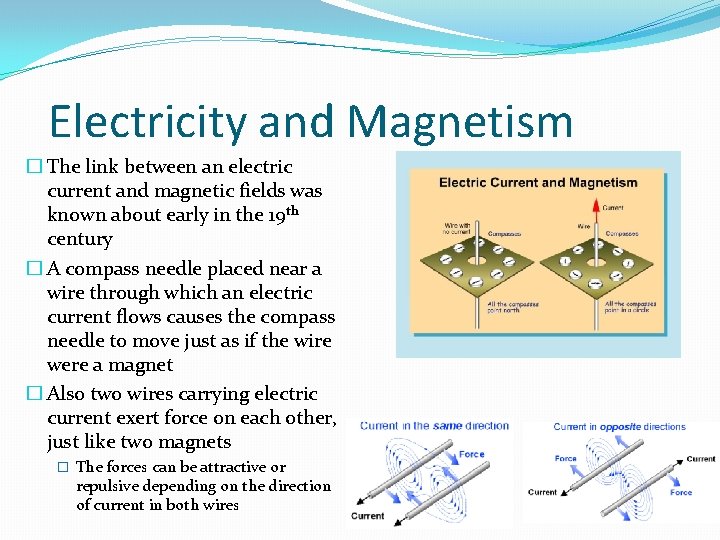
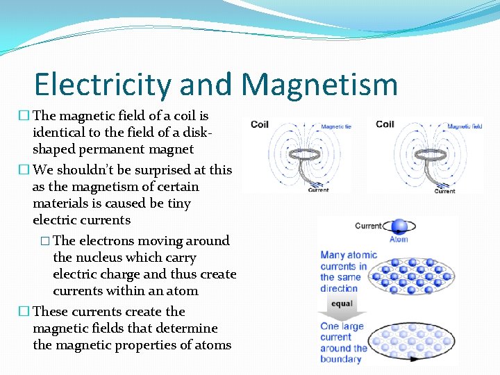
Electricity and Magnetism � The link between an electric current and magnetic fields was known about early in the 19 th century � A compass needle placed near a wire through which an electric current flows causes the compass needle to move just as if the wire were a magnet � Also two wires carrying electric current exert force on each other, just like two magnets � The forces can be attractive or repulsive depending on the direction of current in both wires
Electricity and Magnetism � The magnetic field of a coil is identical to the field of a diskshaped permanent magnet � We shouldn’t be surprised at this as the magnetism of certain materials is caused be tiny electric currents � The electrons moving around the nucleus which carry electric charge and thus create currents within an atom � These currents create the magnetic fields that determine the magnetic properties of atoms
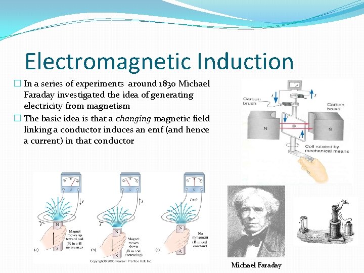
Electromagnetic Induction � In a series of experiments around 1830 Michael Faraday investigated the idea of generating electricity from magnetism � The basic idea is that a changing magnetic field linking a conductor induces an emf (and hence a current) in that conductor Michael Faraday
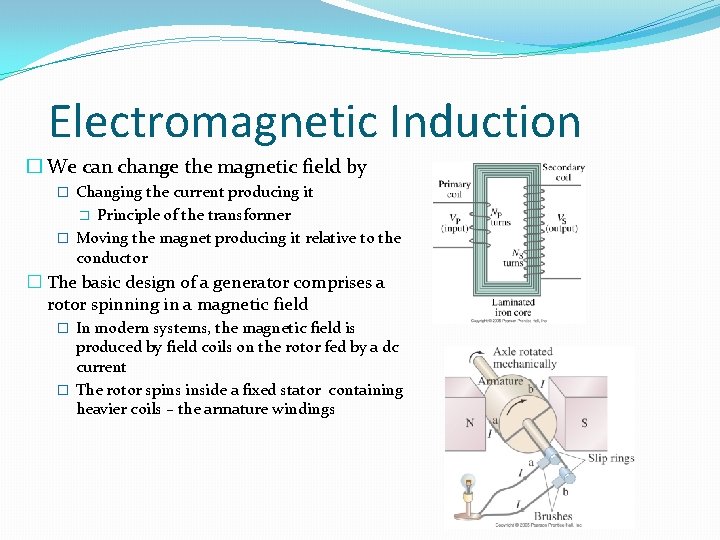
Electromagnetic Induction � We can change the magnetic field by � Changing the current producing it Principle of the transformer � Moving the magnet producing it relative to the conductor � � The basic design of a generator comprises a rotor spinning in a magnetic field � In modern systems, the magnetic field is produced by field coils on the rotor fed by a dc current � The rotor spins inside a fixed stator containing heavier coils – the armature windings
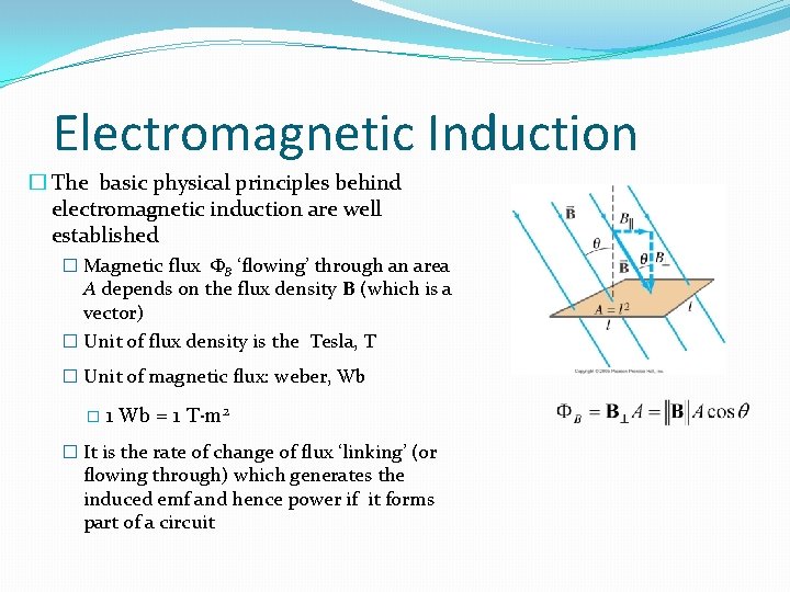
Electromagnetic Induction � The basic physical principles behind electromagnetic induction are well established � Magnetic flux ФB ‘flowing’ through an area A depends on the flux density B (which is a vector) � Unit of flux density is the Tesla, T � Unit of magnetic flux: weber, Wb � 1 Wb = 1 T·m 2 � It is the rate of change of flux ‘linking’ (or flowing through) which generates the induced emf and hence power if it forms part of a circuit
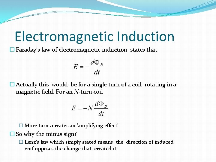
Electromagnetic Induction � Faraday’s law of electromagnetic induction states that � Actually this would be for a single turn of a coil rotating in a magnetic field. For an N-turn coil � More turns creates an ‘amplifying effect’ � So why the minus sign? � Lenz’s law which simply stated means the direction of induced emf opposes the change that created it!
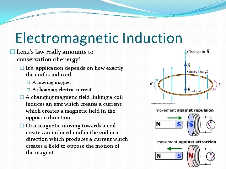
Electromagnetic Induction � Lenz’s law really amounts to conservation of energy! � It’s application depends on how exactly the emf is induced � � A moving magnet A changing electric current � A changing magnetic field linking a coil induces an emf which creates a current which creates a magnetic field in the opposite direction � Or a magnetic moving towards a coil creates an induced emf in the coil in a direction which produces a current which creates a field to oppose the motion of the magnet
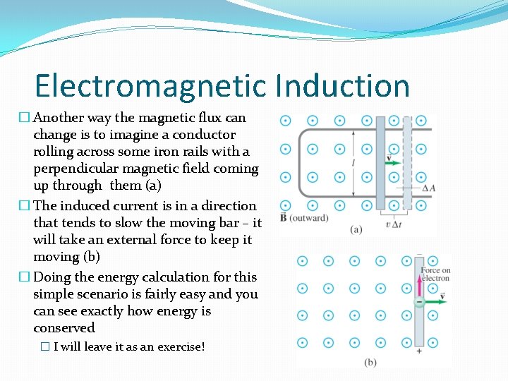
Electromagnetic Induction � Another way the magnetic flux can change is to imagine a conductor rolling across some iron rails with a perpendicular magnetic field coming up through them (a) � The induced current is in a direction that tends to slow the moving bar – it will take an external force to keep it moving (b) � Doing the energy calculation for this simple scenario is fairly easy and you can see exactly how energy is conserved � I will leave it as an exercise!
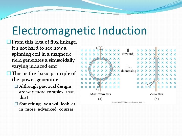
Electromagnetic Induction � From this idea of flux linkage, it’s not hard to see how a spinning coil in a magnetic field generates a sinusoidally varying induced emf � This is the basic principle of the power generator � Although practical designs are way more complex than this! � Something you will look at in more advanced courses
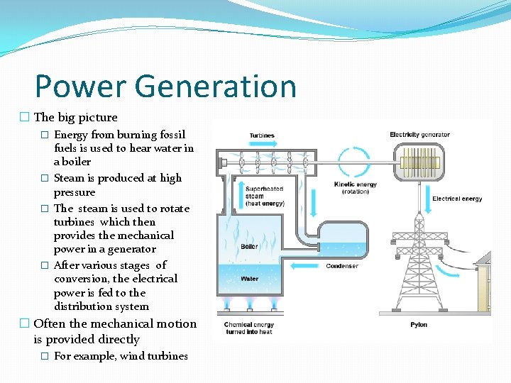
Power Generation � The big picture � Energy from burning fossil fuels is used to hear water in a boiler � Steam is produced at high pressure � The steam is used to rotate turbines which then provides the mechanical power in a generator � After various stages of conversion, the electrical power is fed to the distribution system � Often the mechanical motion is provided directly � For example, wind turbines
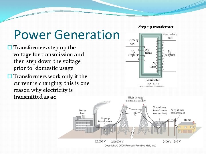
Power Generation � Transformers step up the voltage for transmission and then step down the voltage prior to domestic usage � Transformers work only if the current is changing; this is one reason why electricity is transmitted as ac Step-up transformer
Part II Power Generation from Non-Renewables
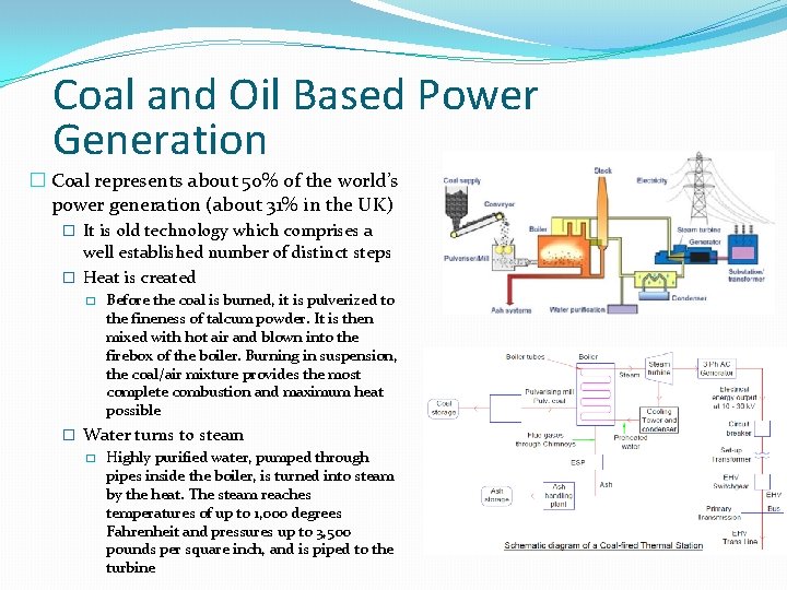
Coal and Oil Based Power Generation � Coal represents about 50% of the world’s power generation (about 31% in the UK) � It is old technology which comprises a well established number of distinct steps � Heat is created � Before the coal is burned, it is pulverized to the fineness of talcum powder. It is then mixed with hot air and blown into the firebox of the boiler. Burning in suspension, the coal/air mixture provides the most complete combustion and maximum heat possible � Water turns to steam � Highly purified water, pumped through pipes inside the boiler, is turned into steam by the heat. The steam reaches temperatures of up to 1, 000 degrees Fahrenheit and pressures up to 3, 500 pounds per square inch, and is piped to the turbine
Coal and Oil Based Power Generation � Steam turns the turbine � The enormous pressure of the steam pushing against a series of giant turbine blades turns the turbine shaft. The turbine shaft is connected to the shaft of the generator, where magnets spin within wire coils to produce electricity � Steam turns back into water � After doing its work in the turbine, the steam is drawn into a condenser, a large chamber in the basement of the power plant. In this important step, millions of gallons of cool water from a nearby source (such as a river or lake) are pumped through a network of tubes running through the condenser. The cool water in the tubes converts the steam back into water that can be used over and over again in the plant. � Finally the cooling water is returned to its source without any contamination, and the steam water is returned to the boiler to repeat the cycle Video. How a coal fired power station works
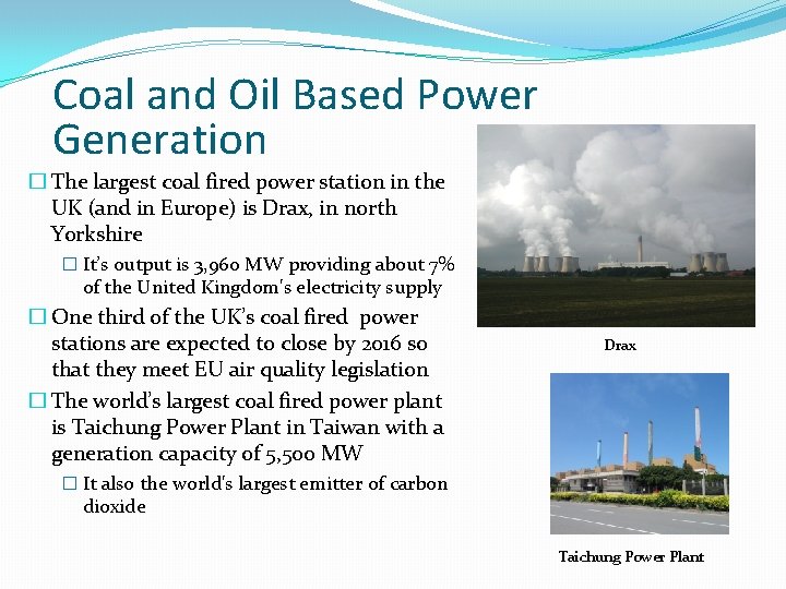
Coal and Oil Based Power Generation � The largest coal fired power station in the UK (and in Europe) is Drax, in north Yorkshire � It’s output is 3, 960 MW providing about 7% of the United Kingdom's electricity supply � One third of the UK’s coal fired power stations are expected to close by 2016 so that they meet EU air quality legislation � The world’s largest coal fired power plant is Taichung Power Plant in Taiwan with a generation capacity of 5, 500 MW Drax � It also the world's largest emitter of carbon dioxide Taichung Power Plant
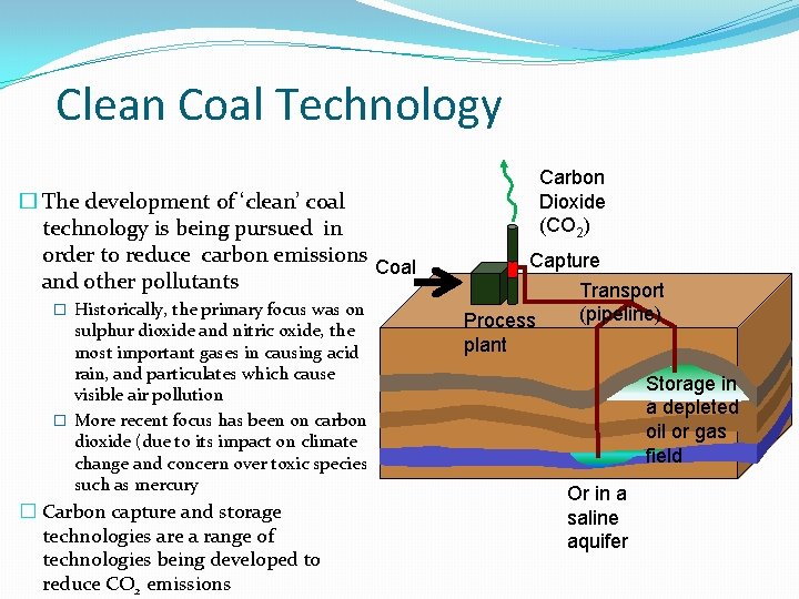
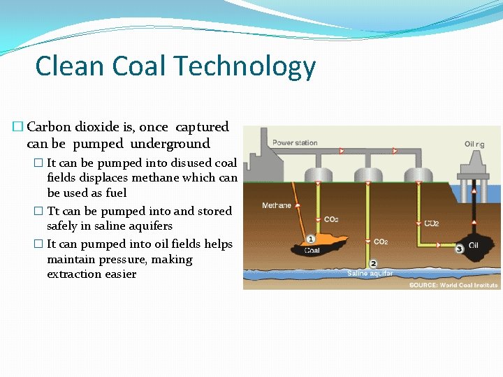
Clean Coal Technology � The development of ‘clean’ coal technology is being pursued in order to reduce carbon emissions Coal and other pollutants � Historically, the primary focus was on sulphur dioxide and nitric oxide, the most important gases in causing acid rain, and particulates which cause visible air pollution � More recent focus has been on carbon dioxide (due to its impact on climate change and concern over toxic species such as mercury � Carbon capture and storage technologies are a range of technologies being developed to reduce CO 2 emissions Carbon Dioxide (CO 2) Capture Transport (pipeline) Process plant Storage in a depleted oil or gas field Or in a saline aquifer
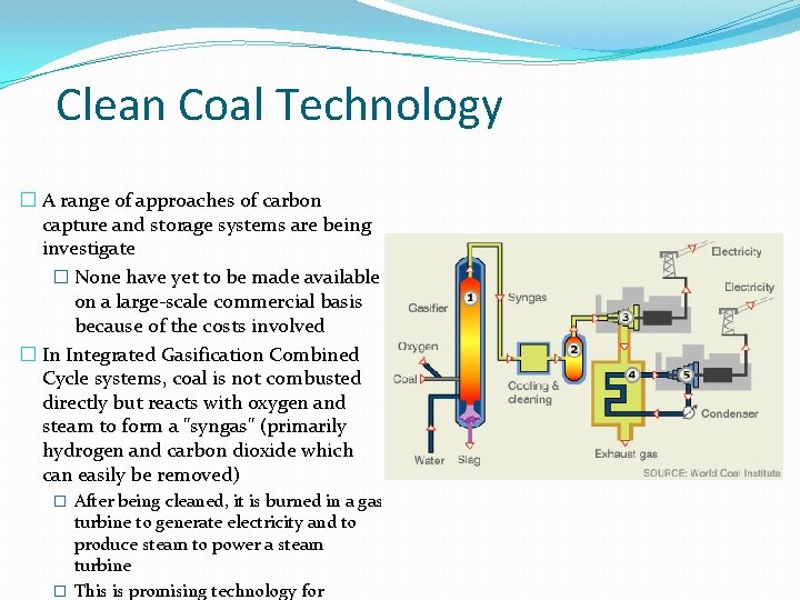
Clean Coal Technology � A range of approaches of carbon capture and storage systems are being investigate � None have yet to be made available on a large-scale commercial basis because of the costs involved � In Integrated Gasification Combined Cycle systems, coal is not combusted directly but reacts with oxygen and steam to form a "syngas" (primarily hydrogen and carbon dioxide which can easily be removed) � After being cleaned, it is burned in a gas turbine to generate electricity and to produce steam to power a steam turbine � This is promising technology for
Clean Coal Technology � Carbon dioxide is, once captured can be pumped underground � It can be pumped into disused coal fields displaces methane which can be used as fuel � Tt can be pumped into and stored safely in saline aquifers � It can pumped into oil fields helps maintain pressure, making extraction easier
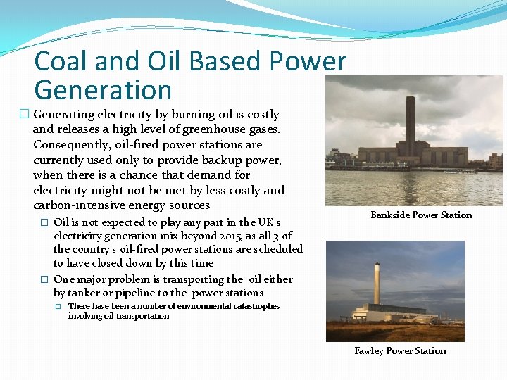
Coal and Oil Based Power Generation � Generating electricity by burning oil is costly and releases a high level of greenhouse gases. Consequently, oil-fired power stations are currently used only to provide backup power, when there is a chance that demand for electricity might not be met by less costly and carbon-intensive energy sources � Oil is not expected to play any part in the UK's Bankside Power Station electricity generation mix beyond 2015, as all 3 of the country's oil-fired power stations are scheduled to have closed down by this time � One major problem is transporting the oil either by tanker or pipeline to the power stations � There have been a number of environmental catastrophes involving oil transportation Fawley Power Station
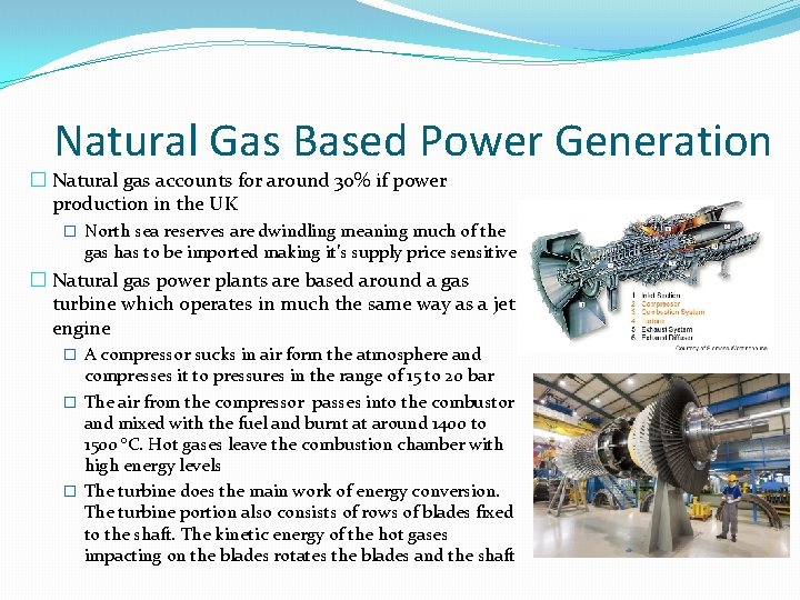
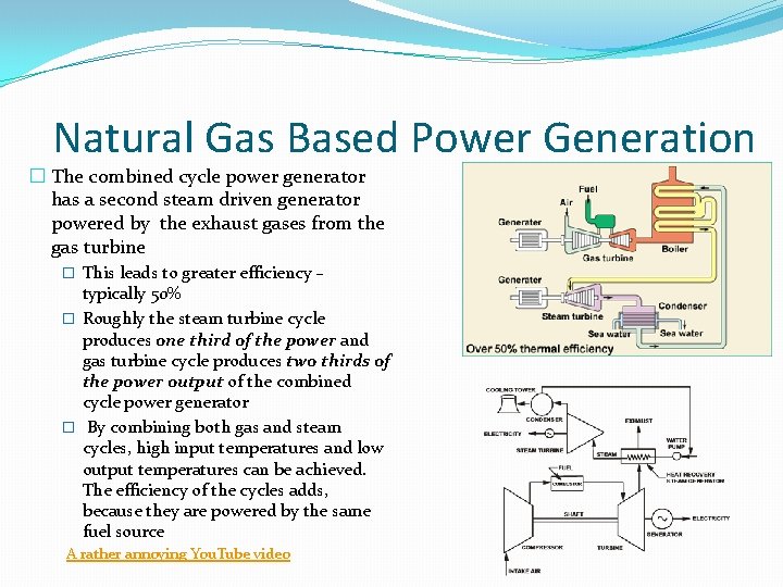
Natural Gas Based Power Generation � Natural gas accounts for around 30% if power production in the UK � North sea reserves are dwindling meaning much of the gas has to be imported making it’s supply price sensitive � Natural gas power plants are based around a gas turbine which operates in much the same way as a jet engine � A compressor sucks in air form the atmosphere and compresses it to pressures in the range of 15 to 20 bar � The air from the compressor passes into the combustor and mixed with the fuel and burnt at around 1400 to 1500 °C. Hot gases leave the combustion chamber with high energy levels � The turbine does the main work of energy conversion. The turbine portion also consists of rows of blades fixed to the shaft. The kinetic energy of the hot gases impacting on the blades rotates the blades and the shaft
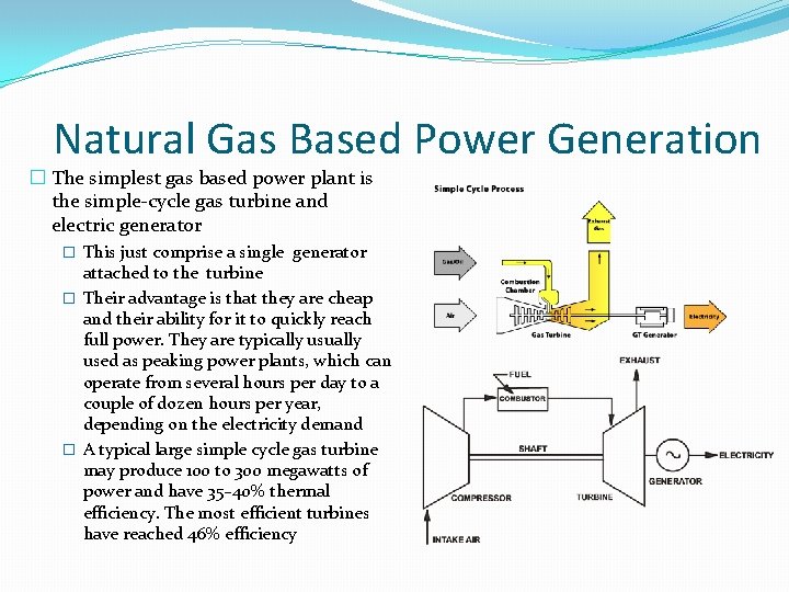
Natural Gas Based Power Generation � The simplest gas based power plant is the simple-cycle gas turbine and electric generator � This just comprise a single generator attached to the turbine � Their advantage is that they are cheap and their ability for it to quickly reach full power. They are typically usually used as peaking power plants, which can operate from several hours per day to a couple of dozen hours per year, depending on the electricity demand � A typical large simple cycle gas turbine may produce 100 to 300 megawatts of power and have 35– 40% thermal efficiency. The most efficient turbines have reached 46% efficiency
Natural Gas Based Power Generation � The combined cycle power generator has a second steam driven generator powered by the exhaust gases from the gas turbine � This leads to greater efficiency – typically 50% � Roughly the steam turbine cycle produces one third of the power and gas turbine cycle produces two thirds of the power output of the combined cycle power generator � By combining both gas and steam cycles, high input temperatures and low output temperatures can be achieved. The efficiency of the cycles adds, because they are powered by the same fuel source A rather annoying You. Tube video
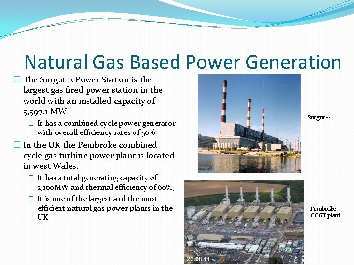
Natural Gas Based Power Generation � The Surgut-2 Power Station is the largest gas fired power station in the world with an installed capacity of 5, 597. 1 MW � It has a combined cycle power generator Surgut -2 with overall efficiency rates of 56% � In the UK the Pembroke combined cycle gas turbine power plant is located in west Wales. � It has a total generating capacity of 2, 160 MW and thermal efficiency of 60%, � It is one of the largest and the most efficient natural gas power plants in the UK Pembroke CCGT plant
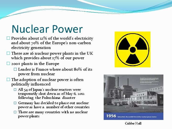
Nuclear Power � Provides about 12% of the world’s electricity and about 70% of the Europe’s non-carbon electricity generation � There are 16 nuclear power plants in the UK which provides about 17% of our power � 200+ plants in the Europe � Leader is France where about 80% of its power from nuclear � The adoption of nuclear power is often politically influenced � All 54 of Japan's nuclear reactors were temporarily shut down as of May 6, 2012 following the Fukushima disaster � Germany has decided to phase out nuclear power as have a number of other countries � There are many countries with no nuclear power plants Calder Hall
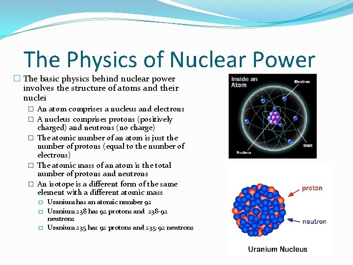
The Physics of Nuclear Power � The basic physics behind nuclear power involves the structure of atoms and their nuclei � An atom comprises a nucleus and electrons � A nucleus comprises protons (positively charged) and neutrons (no charge) � The atomic number of an atom is just the number of protons (equal to the number of electrons) � The atomic mass of an atom is the total number of protons and neutrons � An isotope is a different form of the same element with a different atomic mass � � � Uranium has an atomic number 92 Uranium 238 has 92 protons and 238 -92 neutrons Uranium 235 has 92 protons and 235 -92 neutrons
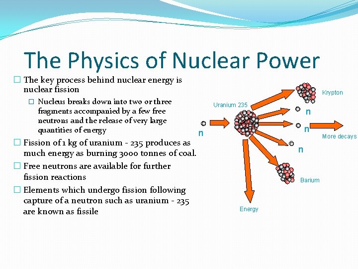
The Physics of Nuclear Power � The key process behind nuclear energy is nuclear fission Krypton � Nucleus breaks down into two or three fragments accompanied by a few free neutrons and the release of very large quantities of energy � Fission of 1 kg of uranium - 235 produces as much energy as burning 3000 tonnes of coal. � Free neutrons are available for further fission reactions � Elements which undergo fission following capture of a neutron such as uranium - 235 are known as fissile Uranium 235 n n Barium Energy More decays
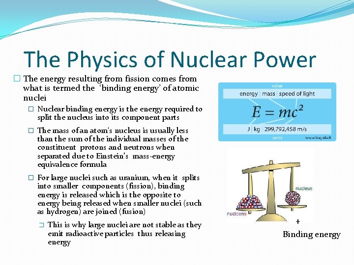
The Physics of Nuclear Power � The energy resulting from fission comes from what is termed the ‘binding energy’ of atomic nuclei � Nuclear binding energy is the energy required to split the nucleus into its component parts � The mass of an atom's nucleus is usually less than the sum of the individual masses of the constituent protons and neutrons when separated due to Einstein’s mass-energy equivalence formula � For large nuclei such as uranium, when it splits into smaller components (fission), binding energy is released which is the opposite to energy being released when smaller nuclei (such as hydrogen) are joined (fusion) � This is why large nuclei are not stable as they emit radioactive particles thus releasing energy + Binding energy
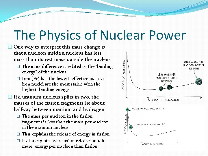
The Physics of Nuclear Power � One way to interpret this mass change is that a nucleon inside a nucleus has less mass than its rest mass outside the nucleus � The mass difference is related to the “binding energy” of the nucleus � Iron (Fe) has the lowest ‘effective mass’ as iron nuclei are the most stable with the highest binding energy � If a uranium nucleus splits in two, the masses of the fission fragments lie about halfway between uranium and hydrogen � The mass per nucleon in the fission fragments is less than the mass per nucleon in the uranium nucleus � This explains the release of energy in fission � It also explains why fusion releases much more energy per nucleon than fission
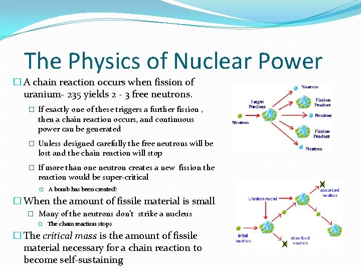
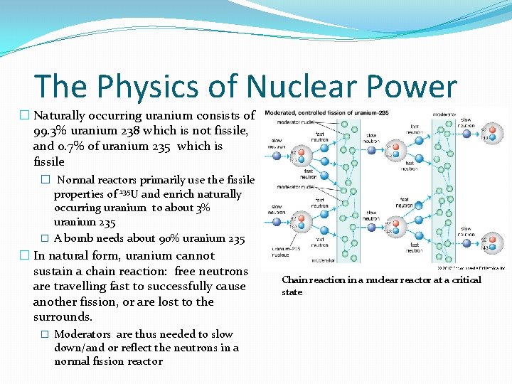
The Physics of Nuclear Power � A chain reaction occurs when fission of uranium- 235 yields 2 - 3 free neutrons. � If exactly one of these triggers a further fission , then a chain reaction occurs, and continuous power can be generated � Unless designed carefully the free neutrons will be lost and the chain reaction will stop � If more than one neutron creates a new fission the reaction would be super-critical � A bomb has been created! � When the amount of fissile material is small � Many of the neutrons don’t strike a nucleus � The chain reaction stops � The critical mass is the amount of fissile material necessary for a chain reaction to become self-sustaining
The Physics of Nuclear Power � Naturally occurring uranium consists of 99. 3% uranium 238 which is not fissile, and 0. 7% of uranium 235 which is fissile � Normal reactors primarily use the fissile properties of 235 U and enrich naturally occurring uranium to about 3% uranium 235 � A bomb needs about 90% uranium 235 � In natural form, uranium cannot sustain a chain reaction: free neutrons are travelling fast to successfully cause another fission, or are lost to the surrounds. � Moderators are thus needed to slow down/and or reflect the neutrons in a normal fission reactor Chain reaction in a nuclear reactor at a critical state
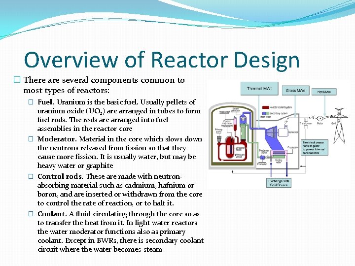
Overview of Reactor Design � There are several components common to most types of reactors: � Fuel. Uranium is the basic fuel. Usually pellets of uranium oxide (UO 2) are arranged in tubes to form fuel rods. The rods are arranged into fuel assemblies in the reactor core � Moderator. Material in the core which slows down the neutrons released from fission so that they cause more fission. It is usually water, but may be heavy water or graphite � Control rods. These are made with neutronabsorbing material such as cadmium, hafnium or boron, and are inserted or withdrawn from the core to control the rate of reaction, or to halt it. � Coolant. A fluid circulating through the core so as to transfer the heat from it. In light water reactors the water moderator functions also as primary coolant. Except in BWRs, there is secondary coolant circuit where the water becomes steam
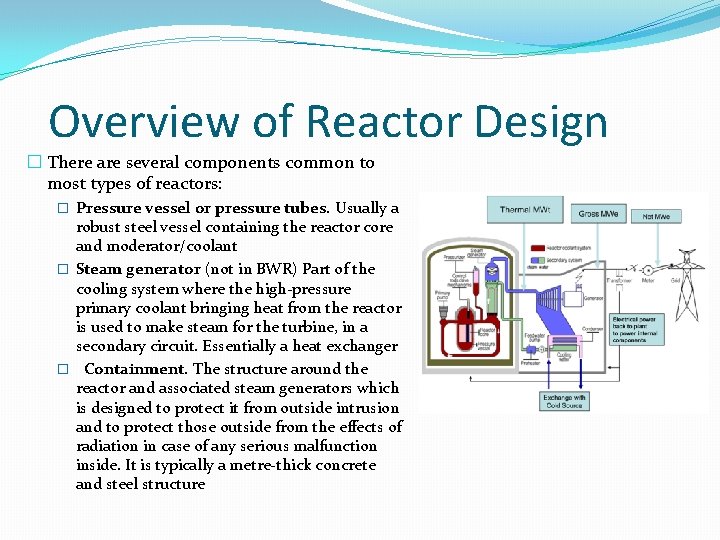
Overview of Reactor Design � There are several components common to most types of reactors: � Pressure vessel or pressure tubes. Usually a robust steel vessel containing the reactor core and moderator/coolant � Steam generator (not in BWR) Part of the cooling system where the high-pressure primary coolant bringing heat from the reactor is used to make steam for the turbine, in a secondary circuit. Essentially a heat exchanger � Containment. The structure around the reactor and associated steam generators which is designed to protect it from outside intrusion and to protect those outside from the effects of radiation in case of any serious malfunction inside. It is typically a metre-thick concrete and steel structure
Summary of Reactor Types � Magnox � Original British Design named after the magnesium alloy used as fuel cladding. 8 reactors of this type were built in France, One in each of Italy, Spain and Japan. 26 units were built in UK � The first Magnox power station, Calder Hall, was the world's second nuclear power station Wylfa � Now only one MAGNOX reactor remains in use – Wylfa on Angelest � AGR - Advanced Gas Cooled Reactor � Solely British design. 14 units are in use. The original demonstration Windscale AGR is now being decommissioned. The last two stations Heysham II and Torness (both with two reactors), were constructed to time and have operated to expectations Torness
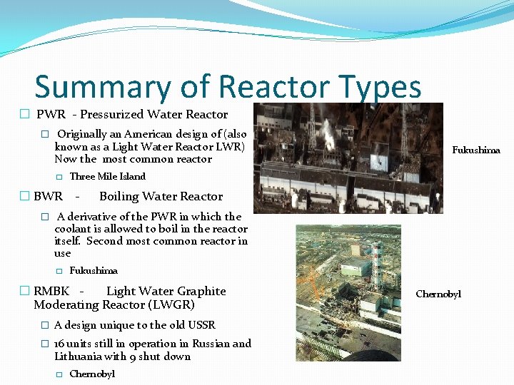
Summary of Reactor Types � PWR - Pressurized Water Reactor � Originally an American design of (also known as a Light Water Reactor LWR) Now the most common reactor � � BWR Fukushima Three Mile Island - Boiling Water Reactor � A derivative of the PWR in which the coolant is allowed to boil in the reactor itself. Second most common reactor in use � Fukushima � RMBK Light Water Graphite Moderating Reactor (LWGR) � A design unique to the old USSR � 16 units still in operation in Russian and Lithuania with 9 shut down � Chernobyl
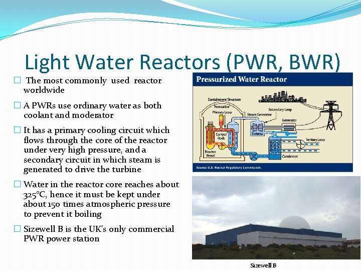
Light Water Reactors (PWR, BWR) � The most commonly used reactor worldwide � A PWRs use ordinary water as both coolant and moderator � It has a primary cooling circuit which flows through the core of the reactor under very high pressure, and a secondary circuit in which steam is generated to drive the turbine � Water in the reactor core reaches about 325°C, hence it must be kept under about 150 times atmospheric pressure to prevent it boiling � Sizewell B is the UK's only commercial PWR power station Sizewell B
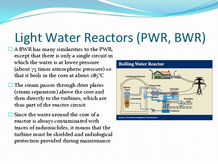
Light Water Reactors (PWR, BWR) � A BWR has many similarities to the PWR, except that there is only a single circuit in which the water is at lower pressure (about 75 times atmospheric pressure) so that it boils in the core at about 285°C � The steam passes through drier plates (steam separators) above the core and then directly to the turbines, which are thus part of the reactor circuit � Since the water around the core of a reactor is always contaminated with traces of radionuclides, it means that the turbine must be shielded and radiological protection provided during maintenance
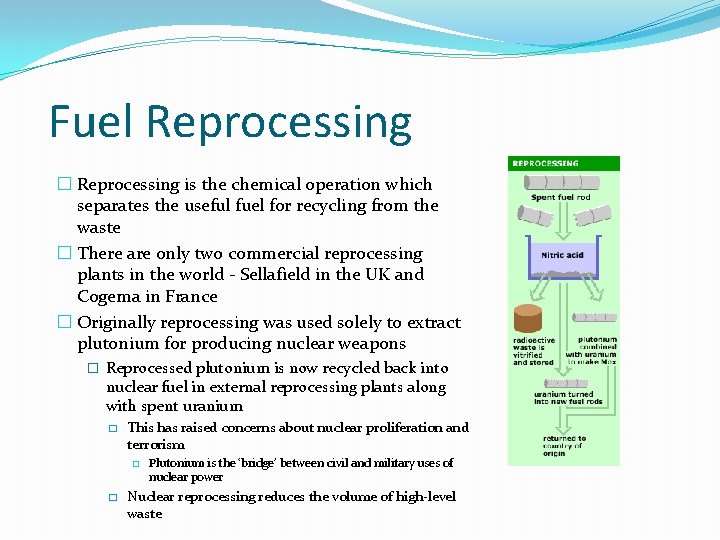
Fuel Reprocessing � Reprocessing is the chemical operation which separates the useful fuel for recycling from the waste � There are only two commercial reprocessing plants in the world - Sellafield in the UK and Cogema in France � Originally reprocessing was used solely to extract plutonium for producing nuclear weapons � Reprocessed plutonium is now recycled back into nuclear fuel in external reprocessing plants along with spent uranium � This has raised concerns about nuclear proliferation and terrorism � � Plutonium is the ‘bridge’ between civil and military uses of nuclear power Nuclear reprocessing reduces the volume of high-level waste
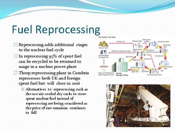
Fuel Reprocessing � Reprocessing adds additional stages to the nuclear fuel cycle � In reprocessing 95% of spent fuel can be recycled to be returned to usage in a nuclear power plant � Thorp reprocessing plant in Cumbria reprocesses both UK and foreign spent fuel but will close in 2016 � Alternatives to reprocessing such as the use air-cooled dry casks to store spent nuclear fuel instead of reprocessing are being considered as the price of raw uranium continues to fall
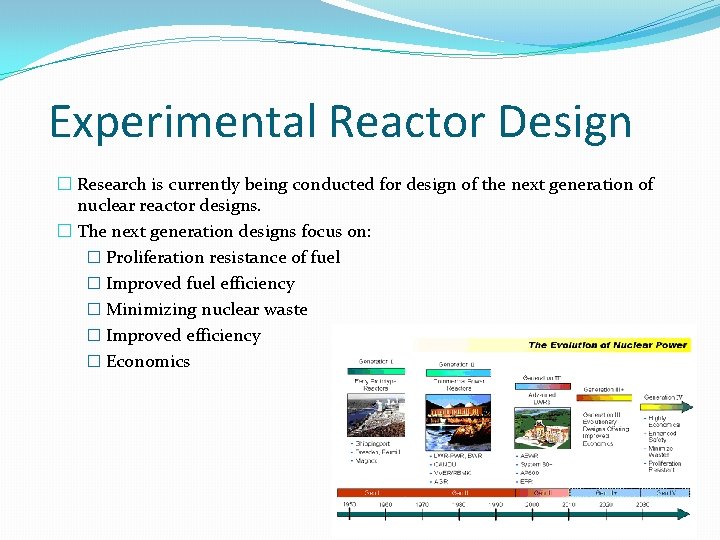
Experimental Reactor Design � Research is currently being conducted for design of the next generation of nuclear reactor designs. � The next generation designs focus on: � Proliferation resistance of fuel � Improved fuel efficiency � Minimizing nuclear waste � Improved efficiency � Economics
Pro’s and Con’s of Nuclear Power � Pros � Less of an immediate environmental impact compared to fossil fuels � Carbon-free source of electricity - no greenhouse gases emitted � May be able to generate H-fuel � Cons � Generates radioactive waste � Many steps require fossil fuels (mining and disposal) � Expensive � Safety issues and public perception
The Future of Nuclear Power � At present there are over 440 nuclear power reactors operating in 30 countries. In total, they provide about 15% of the world’s electricity � Enthusiasm for new nuclear build at present is concentrated in Asia and Russia with relatively weaker enthusiasm in Europe and USA � Worldwide there are 60 new nuclear plants under construction with 131 more proposed � China alone plans a six-fold increase in nuclear power capacity by 2020, and has more than one hundred further large units proposed � The new build programme in Europe (excluding Russia) amounts to just six reactors in four countries: Finland, France Romania and Slovakia � In the UK The government has given the go-ahead for the UK's first new nuclear station in a generation � France's EDF Energy will lead a consortium to build the Hinkley Point C plant in Somerset
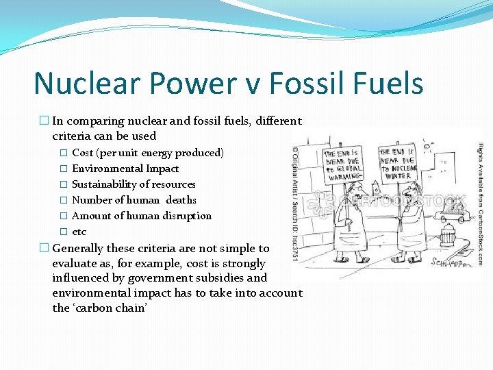
Nuclear Power v Fossil Fuels � In comparing nuclear and fossil fuels, different criteria can be used � Cost (per unit energy produced) � Environmental Impact � Sustainability of resources � Number of human deaths � Amount of human disruption � etc � Generally these criteria are not simple to evaluate as, for example, cost is strongly influenced by government subsidies and environmental impact has to take into account the ‘carbon chain’
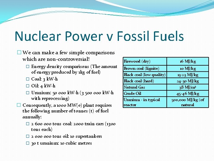
Nuclear Power v Fossil Fuels � We can make a few simple comparisons which are non-controversial! � Energy density comparisons (The amount of energy produced by 1 kg of fuel) � Coal: 3 k. W·h � Oil: 4 k. W·h � Uranium: 50 000 k. W·h (3 500 000 k. W·h with reprocessing) � Consequently, a 1000 MW(e) plant requires the following number of tonnes (t) of fuel annually: � 2 600 000 tons coal: 2000 train cars (1300 tons each) � 2 000 tons oil: 10 supertankers � 30 t uranium: 10 cubic metres Firewood (dry) 16 MJ/kg Brown coal (lignite) 10 MJ/kg Black coal (low quality) 13 -23 MJ/kg Black coal (hard) 24 -30 MJ/kg Natural Gas Crude Oil Uranium - in typical reactor 38 MJ/m 3 45 -46 MJ/kg 500, 000 MJ/kg (of natural
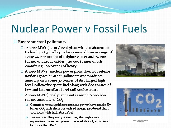
Nuclear Power v Fossil Fuels � Environmental pollutants � A 1000 MW(e) ‘dirty’ coal plant without abatement technology typically produces annually an average of some 44 000 tonnes of sulphur oxides and 22 000 tonnes of nitrous oxides, 320 000 tonnes of ash containing 400 tonnes of heavy � A 1000 MW(e) nuclear power plant does not release noxious gases or other pollutants and produces annually only some 30 tonnes of discharged high level radioactive spent fuel along with 800 tonnes of low and intermediate level radioactive waste � A 1000 MW(e) coal plant emits around 6 000 tonnes annually of CO 2 � � Countries with significant nuclear power have markedly lower CO 2 emissions per unit of energy produced than countries with high fossil fuel France over the past 30 years has, through a rapid expansion in nuclear power, lowered its CO 2 emissions by more than 80%
Part III Power Generation from Renewables
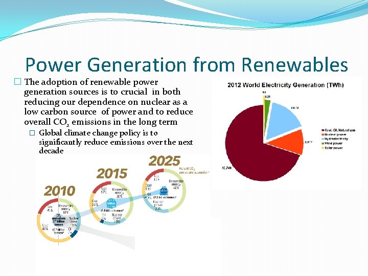
Power Generation from Renewables � The adoption of renewable power generation sources is to crucial in both reducing our dependence on nuclear as a low carbon source of power and to reduce overall CO 2 emissions in the long term � Global climate change policy is to significantly reduce emissions over the next decade
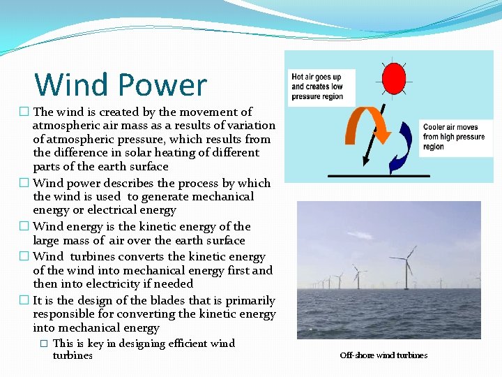
Wind Power � The wind is created by the movement of atmospheric air mass as a results of variation of atmospheric pressure, which results from the difference in solar heating of different parts of the earth surface � Wind power describes the process by which the wind is used to generate mechanical energy or electrical energy � Wind energy is the kinetic energy of the large mass of air over the earth surface � Wind turbines converts the kinetic energy of the wind into mechanical energy first and then into electricity if needed � It is the design of the blades that is primarily responsible for converting the kinetic energy into mechanical energy � This is key in designing efficient wind turbines Off-shore wind turbines
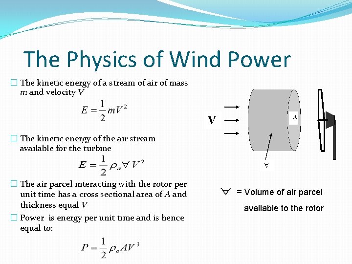
The Physics of Wind Power � The kinetic energy of a stream of air of mass m and velocity V � The kinetic energy of the air stream available for the turbine � The air parcel interacting with the rotor per unit time has a cross sectional area of A and thickness equal V � Power is energy per unit time and is hence equal to: = Volume of air parcel available to the rotor
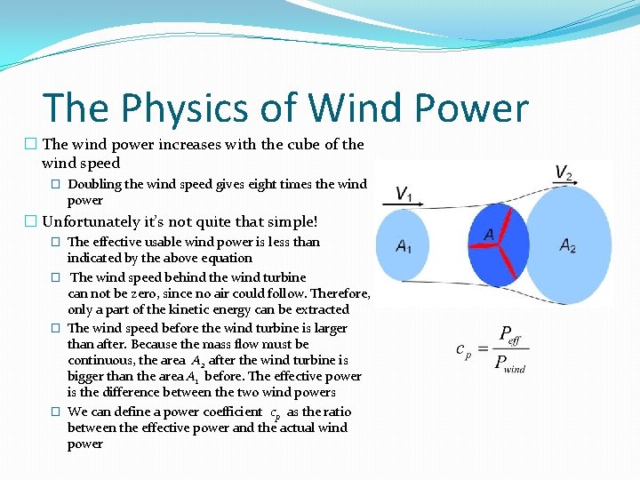
The Physics of Wind Power � The wind power increases with the cube of the wind speed � Doubling the wind speed gives eight times the wind power � Unfortunately it’s not quite that simple! � The effective usable wind power is less than indicated by the above equation � The wind speed behind the wind turbine can not be zero, since no air could follow. Therefore, only a part of the kinetic energy can be extracted � The wind speed before the wind turbine is larger than after. Because the mass flow must be continuous, the area A 2 after the wind turbine is bigger than the area A 1 before. The effective power is the difference between the two wind powers � We can define a power coefficient cp as the ratio between the effective power and the actual wind power
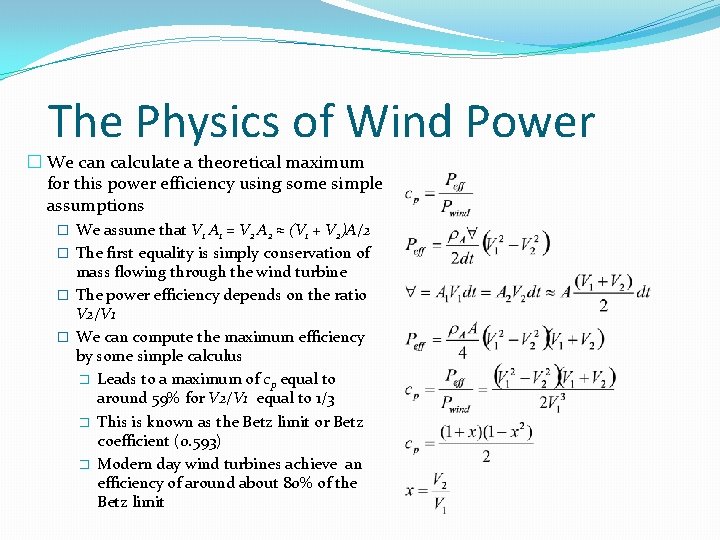
The Physics of Wind Power � We can calculate a theoretical maximum for this power efficiency using some simple assumptions � We assume that V 1 A 1 = V 2 A 2 ≈ (V 1 + V 2)A/2 � The first equality is simply conservation of mass flowing through the wind turbine � The power efficiency depends on the ratio V 2/V 1 � We can compute the maximum efficiency by some simple calculus � Leads to a maximum of cp equal to around 59% for V 2/V 1 equal to 1/3 � This is known as the Betz limit or Betz coefficient (0. 593) � Modern day wind turbines achieve an efficiency of around about 80% of the Betz limit
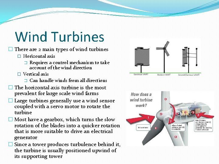
Wind Turbines � There are 2 main types of wind turbines � Horizontal axis Requires a control mechanism to take account of the wind direction � Vertical axis � Can handle winds from all directions � � The horizontal axis turbine is the most prevalent for large scale wind farms � Large turbines generally use a wind sensor coupled with a servo motor to rotate the turbine � Most have a gearbox, which turns the slow rotation of the blades into a quicker rotation that is more suitable to drive an electrical generator � Since a tower produces turbulence behind it, the turbine is usually positioned upwind of its supporting tower
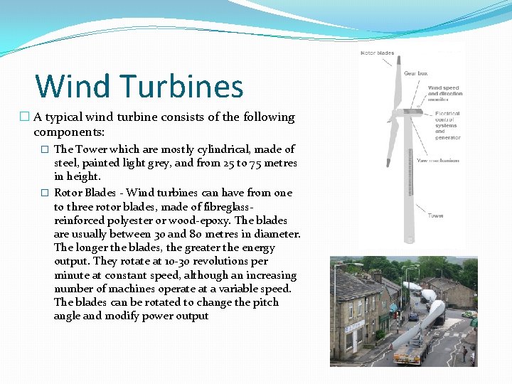
Wind Turbines � A typical wind turbine consists of the following components: � The Tower which are mostly cylindrical, made of steel, painted light grey, and from 25 to 75 metres in height. � Rotor Blades - Wind turbines can have from one to three rotor blades, made of fibreglassreinforced polyester or wood-epoxy. The blades are usually between 30 and 80 metres in diameter. The longer the blades, the greater the energy output. They rotate at 10 -30 revolutions per minute at constant speed, although an increasing number of machines operate at a variable speed. The blades can be rotated to change the pitch angle and modify power output
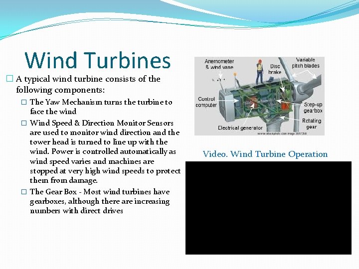
Wind Turbines � A typical wind turbine consists of the following components: � The Yaw Mechanism turns the turbine to face the wind � Wind Speed & Direction Monitor Sensors are used to monitor wind direction and the tower head is turned to line up with the wind. Power is controlled automatically as wind speed varies and machines are stopped at very high wind speeds to protect them from damage. � The Gear Box - Most wind turbines have gearboxes, although there are increasing numbers with direct drives Video. Wind Turbine Operation
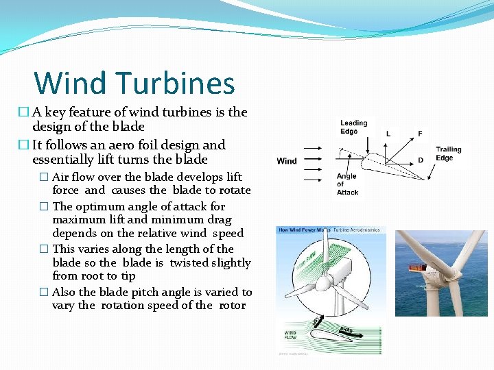
Wind Turbines � A key feature of wind turbines is the design of the blade � It follows an aero foil design and essentially lift turns the blade � Air flow over the blade develops lift force and causes the blade to rotate � The optimum angle of attack for maximum lift and minimum drag depends on the relative wind speed � This varies along the length of the blade so the blade is twisted slightly from root to tip � Also the blade pitch angle is varied to vary the rotation speed of the rotor
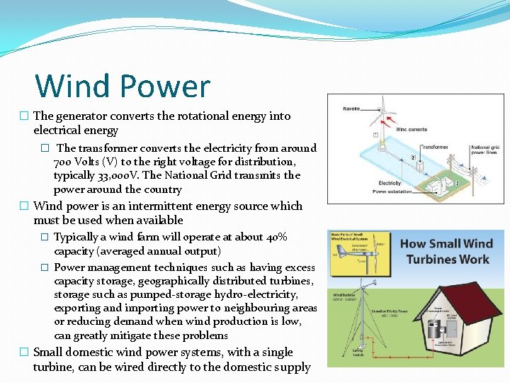
Wind Power � The generator converts the rotational energy into electrical energy � The transformer converts the electricity from around 700 Volts (V) to the right voltage for distribution, typically 33, 000 V. The National Grid transmits the power around the country � Wind power is an intermittent energy source which must be used when available � Typically a wind farm will operate at about 40% capacity (averaged annual output) � Power management techniques such as having excess capacity storage, geographically distributed turbines, storage such as pumped-storage hydro-electricity, exporting and importing power to neighbouring areas or reducing demand when wind production is low, can greatly mitigate these problems � Small domestic wind power systems, with a single turbine, can be wired directly to the domestic supply
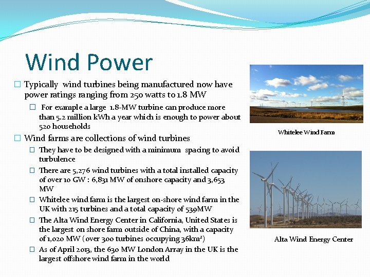
Wind Power � Typically wind turbines being manufactured now have power ratings ranging from 250 watts to 1. 8 MW � For example a large 1. 8 -MW turbine can produce more than 5. 2 million k. Wh a year which is enough to power about 520 households � Wind farms are collections of wind turbines Whitelee Wind Farm � They have to be designed with a minimum spacing to avoid � � turbulence There are 5, 276 wind turbines with a total installed capacity of over 10 GW : 6, 831 MW of onshore capacity and 3, 653 MW Whitelee wind farm is the largest on-shore wind farm in the UK with 215 turbines and a total capacity of 539 MW The Alta Wind Energy Center in California, United States is the largest on shore farm outside of China, with a capacity of 1, 020 MW (over 300 turbines occupying 36 km 2) As of April 2013, the 630 MW London Array in the UK is the largest offshore wind farm in the world Alta Wind Energy Center
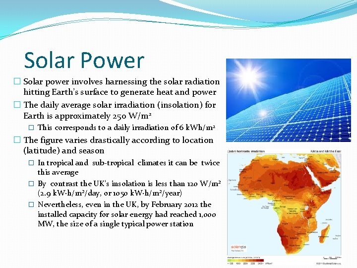
Solar Power � Solar power involves harnessing the solar radiation hitting Earth’s surface to generate heat and power � The daily average solar irradiation (insolation) for Earth is approximately 250 W/m 2 � This corresponds to a daily irradiation of 6 k. Wh/m 2 � The figure varies drastically according to location (latitude) and season � In tropical and sub-tropical climates it can be twice this average � By contrast the UK's insolation is less than 120 W/m² (2. 9 k. W·h/m²/day, or 1050 k. W·h/m²/year) � Nevertheless, even in the UK, by February 2012 the installed capacity for solar energy had reached 1, 000 MW, the size of a single typical power station
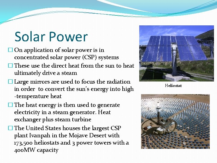
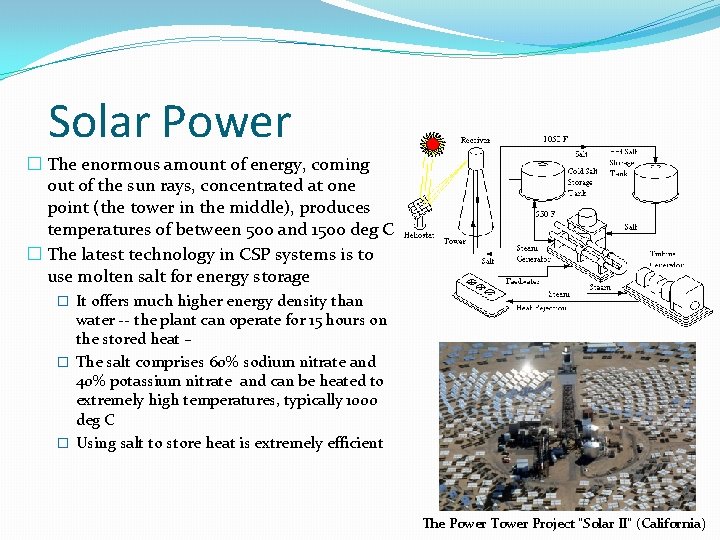
Solar Power � On application of solar power is in concentrated solar power (CSP) systems � These use the direct heat from the sun to heat ultimately drive a steam � Large mirrors are used to focus the radiation in order to convert the sun's energy into high -temperature heat � The heat energy is then used to generate electricity in a steam generator. Heat exchanger plus steam turbine � The United States houses the largest CSP plant Ivanpah in the Mojave Desert with 173, 500 heliostats and 3 power towers with a 400 MW capacity Heliostat
Solar Power � The enormous amount of energy, coming out of the sun rays, concentrated at one point (the tower in the middle), produces temperatures of between 500 and 1500 deg C � The latest technology in CSP systems is to use molten salt for energy storage � It offers much higher energy density than water -- the plant can operate for 15 hours on the stored heat – � The salt comprises 60% sodium nitrate and 40% potassium nitrate and can be heated to extremely high temperatures, typically 1000 deg C � Using salt to store heat is extremely efficient The Power Tower Project "Solar II" (California)
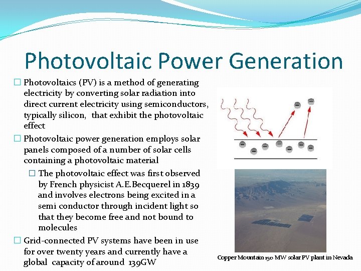
Photovoltaic Power Generation � Photovoltaics (PV) is a method of generating electricity by converting solar radiation into direct current electricity using semiconductors, typically silicon, that exhibit the photovoltaic effect � Photovoltaic power generation employs solar panels composed of a number of solar cells containing a photovoltaic material � The photovoltaic effect was first observed by French physicist A. E. Becquerel in 1839 and involves electrons being excited in a semi conductor through incident light so that they become free and not bound to molecules � Grid-connected PV systems have been in use for over twenty years and currently have a global capacity of around 139 GW Copper Mountain 150 MW solar PV plant in Nevada
The Physics of Photovoltaic Cells � PV cells are based around semi-conductors of which the vast majority use silicon � The atomic structure of silicon is the key to understanding it’s behaviour as a semiconductor � A silicon atom has 14 electrons and 14 protons ee- e-ee- e e- 14+ 14 - 14+ 14 - e- N 14+ e- - - e- ee-e e- e- -e e ee 14+ 14 - - ee- 14+ 14 -
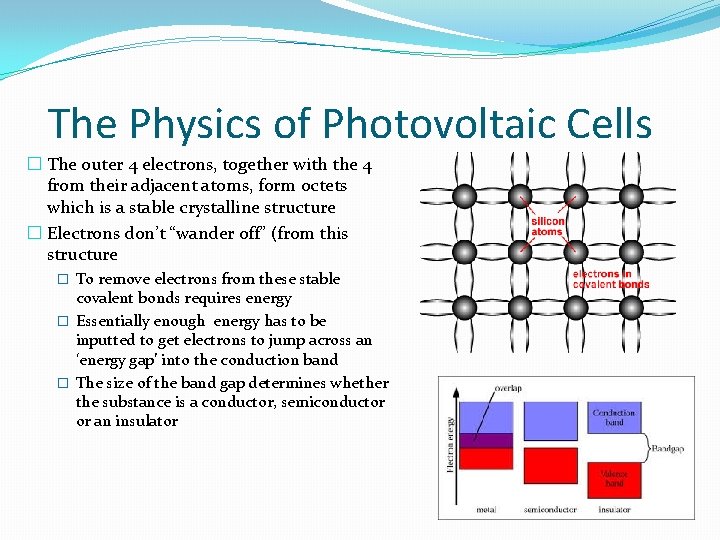
The Physics of Photovoltaic Cells � The outer 4 electrons, together with the 4 from their adjacent atoms, form octets which is a stable crystalline structure � Electrons don’t “wander off” (from this structure � To remove electrons from these stable covalent bonds requires energy � Essentially enough energy has to be inputted to get electrons to jump across an ‘energy gap’ into the conduction band � The size of the band gap determines whether the substance is a conductor, semiconductor or an insulator
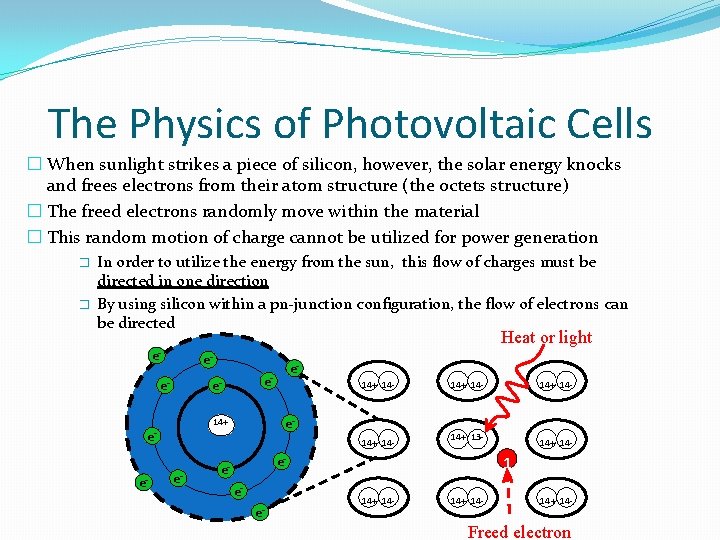
The Physics of Photovoltaic Cells � When sunlight strikes a piece of silicon, however, the solar energy knocks and frees electrons from their atom structure (the octets structure) � The freed electrons randomly move within the material � This random motion of charge cannot be utilized for power generation � � In order to utilize the energy from the sun, this flow of charges must be directed in one direction By using silicon within a pn-junction configuration, the flow of electrons can be directed Heat or light ee- e-ee- N 14+ ee- - - e- ee-e- e- -e eee- e- e- 14+ 14 - e 14+ 14 - 14+ 13 - 14+ 14 - ee- 14+ 14 - - 1 14+ 14 - Freed electron
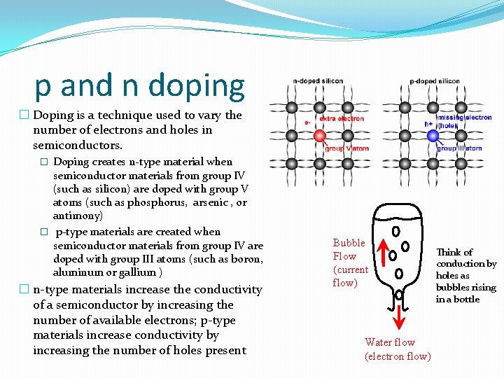
p and n doping � Doping is a technique used to vary the number of electrons and holes in semiconductors. � Doping creates n-type material when semiconductor materials from group IV (such as silicon) are doped with group V atoms (such as phosphorus, arsenic , or antimony) � p-type materials are created when semiconductor materials from group IV are doped with group III atoms (such as boron, aluminum or gallium ) � n-type materials increase the conductivity of a semiconductor by increasing the number of available electrons; p-type materials increase conductivity by increasing the number of holes present Bubble Flow (current flow) Water flow (electron flow) Think of conduction by holes as bubbles rising in a bottle
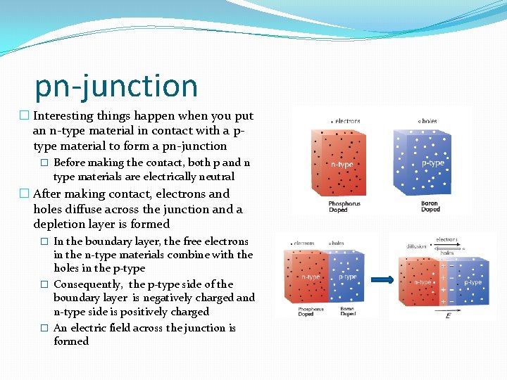
pn-junction � Interesting things happen when you put an n-type material in contact with a ptype material to form a pn-junction � Before making the contact, both p and n type materials are electrically neutral � After making contact, electrons and holes diffuse across the junction and a depletion layer is formed � In the boundary layer, the free electrons in the n-type materials combine with the holes in the p-type � Consequently, the p-type side of the boundary layer is negatively charged and n-type side is positively charged � An electric field across the junction is formed
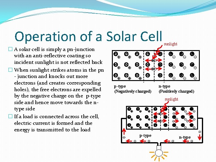
Operation of a Solar Cell � A solar cell is simply a pn-junction with an anti-reflective coating so incident sunlight is not reflected back � When sunlight strikes atoms in the pn - junction and knocks out more electrons (and creates corresponding holes), the free electrons are expelled by the negative charge on the p-type side and hence move towards the ntype side � If a load is connected across the cell, electric current is formed and the energy is transmitted to the load p-type (Negatively charged) sunlight n-type (Positively charged) sunlight p-type n-type
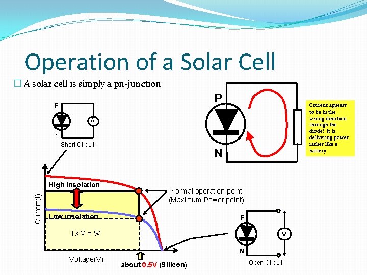
Operation of a Solar Cell � A solar cell is simply a pn-junction P P Current appears to be in the wrong direction through the diode! It is delivering power rather like a battery A N Short Circuit Current(I) High insolation N Normal operation point (Maximum Power point) Low insolation P Ix. V=W V N Voltage(V) about 0. 5 V (Silicon) Open Circuit
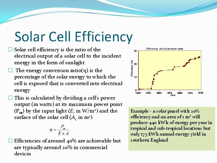
Solar Cell Efficiency � Solar cell efficiency is the ratio of the electrical output of a solar cell to the incident energy in the form of sunlight � The energy conversion ratio(η) is the percentage of the solar energy to which the cell is exposed that is converted into electrical energy � This is calculated by dividing a cell's power output (in watts) at its maximum power point (Pm) by the input light (E, in W/m 2) and the surface of the solar cell (Ac in m 2) � Efficiencies of around 40% are achievable but are typically around 20% in commercial devices Example - a solar panel with 20% efficiency and an area of 1 m² will produce 440 k. Wh of energy per year in tropical and sub-tropical locations but only 175 k. Wh annual energy yield in southern England
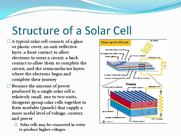
Structure of a Solar Cell � A typical solar cell consists of a glass or plastic cover, an anti-reflective layer, a front contact to allow electrons to enter a circuit, a back contact to allow them to complete the circuit, and the semiconductor layers where the electrons begin and complete their journey � Because the amount of power produced by a single solar cell is relatively small, one to two watts, designers group solar cells together to form modules (panels) that supply a more useful level of voltage, current, and power � Solar cells may be connected in series to produce higher voltages
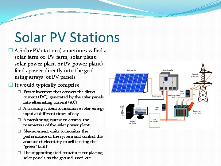
Solar PV Stations � A Solar PV station (sometimes called a solar farm or PV farm, solar plant, solar power plant or PV power plant) feeds power directly into the grid using arrays of PV panels � It would typically comprise � Power inverters that convert the direct � � current (DC), generated by the solar panels into alternating current (AC) A tracking system to maximize solar energy input at different times of day A monitoring system to control the parameters of the solar power plant Measurement units to monitor the performance of the system and control the amount of electricity to sell it using the "green" tariff The supporting steel structures for placing solar panels on the ground, roof, etc
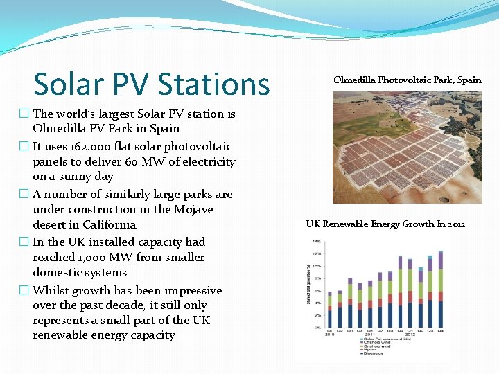
Solar PV Stations � The world’s largest Solar PV station is Olmedilla PV Park in Spain � It uses 162, 000 flat solar photovoltaic panels to deliver 60 MW of electricity on a sunny day � A number of similarly large parks are under construction in the Mojave desert in California � In the UK installed capacity had reached 1, 000 MW from smaller domestic systems � Whilst growth has been impressive over the past decade, it still only represents a small part of the UK renewable energy capacity Olmedilla Photovoltaic Park, Spain UK Renewable Energy Growth In 2012
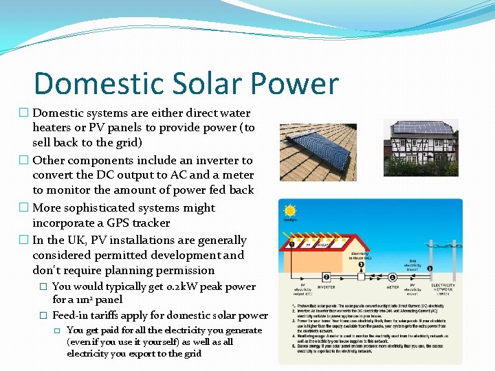
Domestic Solar Power � Domestic systems are either direct water heaters or PV panels to provide power (to sell back to the grid) � Other components include an inverter to convert the DC output to AC and a meter to monitor the amount of power fed back � More sophisticated systems might incorporate a GPS tracker � In the UK, PV installations are generally considered permitted development and don't require planning permission � You would typically get 0. 2 k. W peak power for a 1 m 2 panel � Feed-in tariffs apply for domestic solar power � You get paid for all the electricity you generate (even if you use it yourself) as well as all electricity you export to the grid
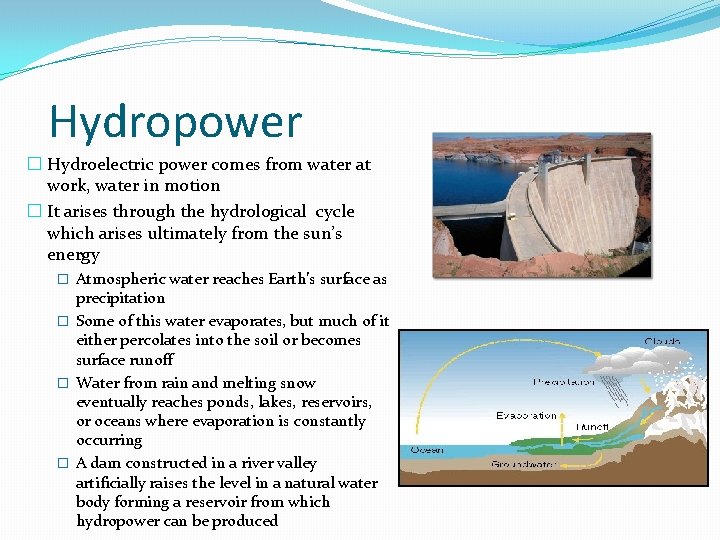
Hydropower � Hydroelectric power comes from water at work, water in motion � It arises through the hydrological cycle which arises ultimately from the sun’s energy � Atmospheric water reaches Earth’s surface as precipitation � Some of this water evaporates, but much of it either percolates into the soil or becomes surface runoff � Water from rain and melting snow eventually reaches ponds, lakes, reservoirs, or oceans where evaporation is constantly occurring � A dam constructed in a river valley artificially raises the level in a natural water body forming a reservoir from which hydropower can be produced
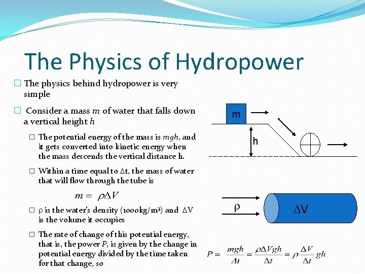
The Physics of Hydropower � The physics behind hydropower is very simple � Consider a mass m of water that falls down a vertical height h m � The potential energy of the mass is mgh, and h it gets converted into kinetic energy when the mass descends the vertical distance h. � Within a time equal to t, the mass of water that will flow through the tube is � is the water’s density (1000 kg/m 3) and V is the volume it occupies � The rate of change of this potential energy, that is, the power P, is given by the change in potential energy divided by the time taken for that change, so V
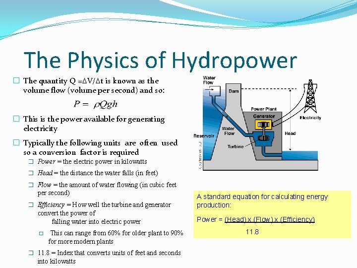
The Physics of Hydropower � The quantity Q = V/ t is known as the volume flow (volume per second) and so: � This is the power available for generating electricity � Typically the following units are often used so a conversion factor is required � Power = the electric power in kilowatts � Head = the distance the water falls (in feet) � Flow = the amount of water flowing (in cubic feet per second) � Efficiency = How well the turbine and generator convert the power of falling water into electric power � This can range from 60% for older plant to 90% for more modern plants � 11. 8 = Index that converts units of feet and seconds into kilowatts A standard equation for calculating energy production: Power = (Head) x (Flow) x (Efficiency) 11. 8
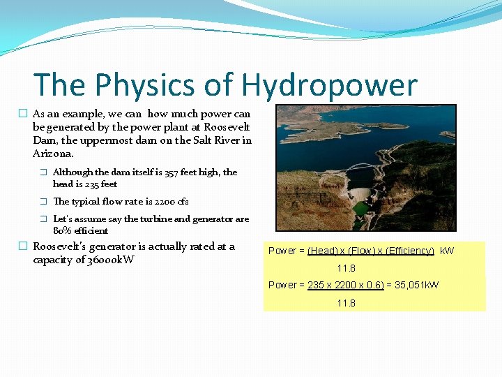
The Physics of Hydropower � As an example, we can how much power can be generated by the power plant at Roosevelt Dam, the uppermost dam on the Salt River in Arizona. � Although the dam itself is 357 feet high, the head is 235 feet � The typical flow rate is 2200 cfs � Let’s assume say the turbine and generator are 80% efficient � Roosevelt’s generator is actually rated at a capacity of 36000 k. W Power = (Head) x (Flow) x (Efficiency) k. W 11. 8 Power = 235 x 2200 x 0. 6) = 35, 051 k. W 11. 8
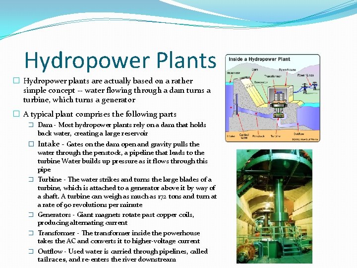
Hydropower Plants � Hydropower plants are actually based on a rather simple concept -- water flowing through a dam turns a turbine, which turns a generator � A typical plant comprises the following parts � Dam - Most hydropower plants rely on a dam that holds back water, creating a large reservoir � Intake - Gates on the dam open and gravity pulls the water through the penstock, a pipeline that leads to the turbine Water builds up pressure as it flows through this pipe � Turbine - The water strikes and turns the large blades of a turbine, which is attached to a generator above it by way of a shaft. A turbine can weigh as much as 172 tons and turn at a rate of 90 revolutions per minute � Generators - Giant magnets rotate past copper coils, producing alternating current � Transformer - The transformer inside the powerhouse takes the AC and converts it to higher-voltage current � Outflow - Used water is carried through pipelines, called tailraces, and re-enters the river downstream
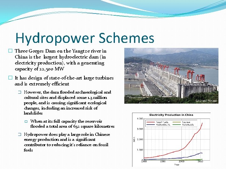
Hydropower Schemes � Three Gorges Dam on the Yangtze river in China is the largest hydroelectric dam (in electricity production), with a generating capacity of 22, 500 MW � It has design of state-of-the-art large turbines and is extremely efficient � However, the dam flooded archaeological and cultural sites and displaced some 1. 3 million people, and is causing significant ecological changes, including an increased risk of landslides � When at its full capacity the reservoir flooded a total area of 632 square kilometres � Hydropower does play a large role in Chinese energy production and is a significant contributor to reducing it’s reliance on fossil fuels
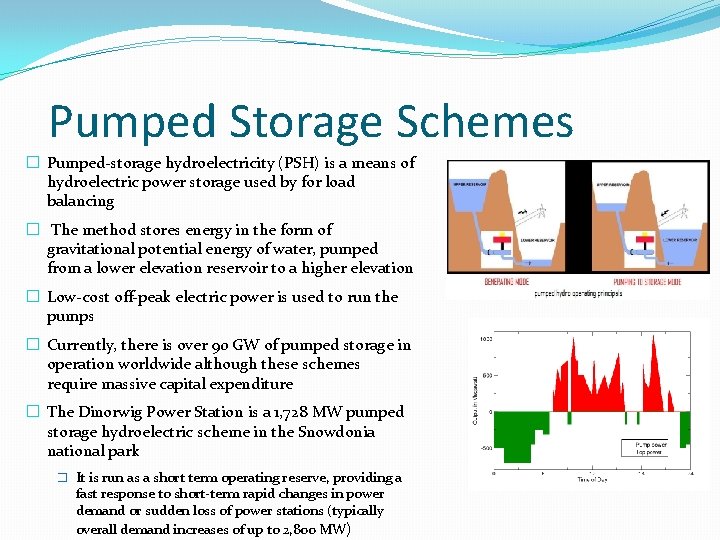
Pumped Storage Schemes � Pumped-storage hydroelectricity (PSH) is a means of hydroelectric power storage used by for load balancing � The method stores energy in the form of gravitational potential energy of water, pumped from a lower elevation reservoir to a higher elevation � Low-cost off-peak electric power is used to run the pumps � Currently, there is over 90 GW of pumped storage in operation worldwide although these schemes require massive capital expenditure � The Dinorwig Power Station is a 1, 728 MW pumped storage hydroelectric scheme in the Snowdonia national park � It is run as a short term operating reserve, providing a fast response to short-term rapid changes in power demand or sudden loss of power stations (typically overall demand increases of up to 2, 800 MW)