EECE 1101 Electrical Engineering Lab I Nor Farahidah

EECE 1101 Electrical Engineering Lab I

• Nor Farahidah Za’bah Taaruf • Room number : E 2 -2 -13. 12 • Phone number : 03 -61964562 • Email address : adah 510@iium. edu. my • The lab technician is • Br. Shahbudin bin Basri • The lab demonstrator is Br. Sazib • Course website: • http: //staff. iium. edu. my/adah 510

Weeks 2 3 4 Topics Introduction to Lab Experiment #1: Ohm’s Law & Series and parallel circuits Experiment #2: Kirchoff’s voltage and current laws Task/Reading Experiment #1 Experiment #2 5 Experiment #3: Thevenin’s and Norton’s Experiment #3 theorem and Maximum power transfer theorem 6 7 8 Experiment #4: Superposition Theorem Introduction to Simulation Software PSPICE Experiment #5: Diode Characteristic and Application Experiment #6: Inverting and Non-Inverting Op -Amp (Theoretical and Demonstration) Design an Amplifier using Op-Amp (Open. Ended Lab) Experiment #7: BJT Characteristic and Biasing Circuits 9 10 12 & 13 14 Experiment #4 Experiment #5 Experiment #6 Experiment #7 Preparation Week Final Test

Assessment Item Quizzes Reports Open Ended Lab PSPICE Final Examination TOTAL % 10 25 10 5 50 100

Safety • Please wear covered shoes – NO SLIPPERS. Otherwise, you will be asked to leave the lab. • Power must be switched off whenever an experiment or project is being assembled, disassembled, or modified.

Tidiness • When the experiment has been satisfactory completed and the results approved by the instructor, the students may disconnect the circuit and return the components and instruments to the locker tidily. • Chairs are to be slid in properly. • DO NOT WRITE anything on the table

Preparation • Read the entire experiment and research any required theory beforehand. Many times an experiment takes longer that one class period simply because a student is not well prepared. • The experiment is performed in pairs (max=3 students per group) but the final test is performed individually • One group = one lab report

Preparation for PSPICE Tutorial • Download 16. 6_Or. CAD_Lite_Capture&PSpice_Products. zip from the any computer in the lab • It is a zipped file, you have to extract the files into a designated folder • Once you have extracted, go to Disk 1 and look for SETUP (it is an application file) to install the software. • One group will require ONE laptop for the tutorial sessions

M 3 10 17 24 M 1 8 15 22 29 T 4 11 18 25 T 2 9 16 23 30 W 5 Intro 12 Lab 1 19 No Lab 26 Lab 2 W 3 SEPTEMBER T 6 13 20 OCTOBER T 4 F 7 14 21 S 8 15 22 S 9 16 23 F 5 12 19 S 6 13 20 S 7 14 21 27 28 Lab 3 10 11 Lab 4 17 18 PSPICE 24 25 26 Lab 5 31 MID SEMESTER BREAK

M 5 T 6 Deepavali 12 13 19 20 26 27 M 3 T 4 10 17 11 18 NOVEMBER W T 7 8 Lab 6 – Theoretical/ Demonstration 14 Lab 6 – Open Ended Lab 21 Lab 7 28 F 9 S 10 S 11 15 16 17 18 23 24 25 22 29 DECEMBER W T 5 6 Final Test 12 13 19 20 30 F 7 S 8 15 S 9 16 14 21 22 Final Exam Starts 23

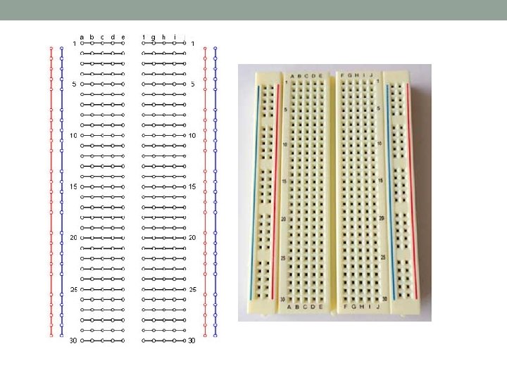
Introduction to Lab Equipment • Bread board and its connections Holes that are labelled with letters means SAME node

• Function Generator • To create AC signals such as Sine-Wave, Triangular Waves and Square Wave • The user can alter its frequency and amplitude Example of a function generator

• Oscilloscope – An equipment to show the obtained result. – Has 2 channels • One for input signal • One for output signal

• DC power supply • To provide DC supply to your circuit which you can measure using digital multi-meter • Only use channel 1 and channel 3 • Make sure the overload light is off • Increase the current knob
 • To measure voltage, turn the knob to DC")
• Digital Multimeter (DMM) • To measure voltage, turn the knob to DC Volts • The DMM is place ACROSS/IN PARALLEL with the device that you are measuring • To measure current, turn the knob to AC (m. A) • The lead is place IN SERIES with the path where the current flows Main reason why DMM failed to work as Ammeter is because students tend to short circuit the two leads.

x +Vs GND +VS x 1 k y GND y

SERIES x A x PARALLEL y y
- Slides: 19