Industrial Electrical Engineering and Automation SmallSignal Modelling and

- Slides: 11
Industrial Electrical Engineering and Automation Small-Signal Modelling and Analysis of DC Distributed Power Systems Per Karlsson © Per Karlsson Small Signal Modelling and Analysis of DC Distributed Power Systems http: //www. iea. lth. se/
Industrial Electrical Engineering and Automation Presentation Outline © Per Karlsson • Introduction • DC power distribution • DC bus voltage control • Small-signal modelling • Small-signal models compared to previous work Small Signal Modelling and Analysis of DC Distributed Power Systems
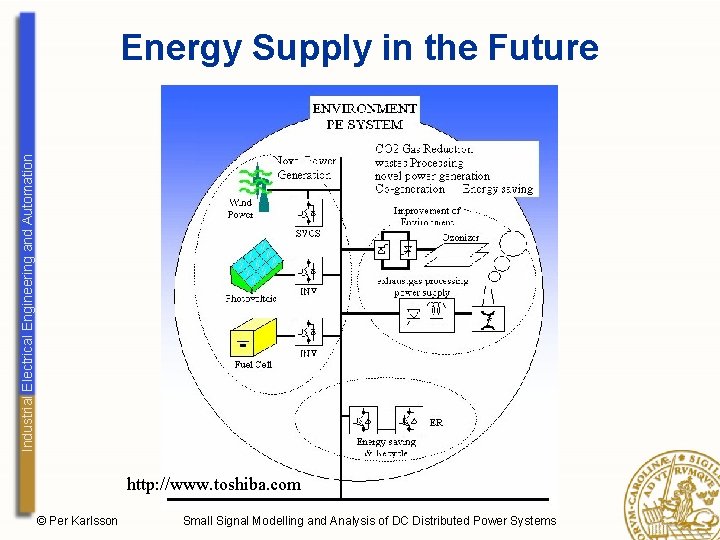
Industrial Electrical Engineering and Automation Energy Supply in the Future http: //www. toshiba. com © Per Karlsson Small Signal Modelling and Analysis of DC Distributed Power Systems
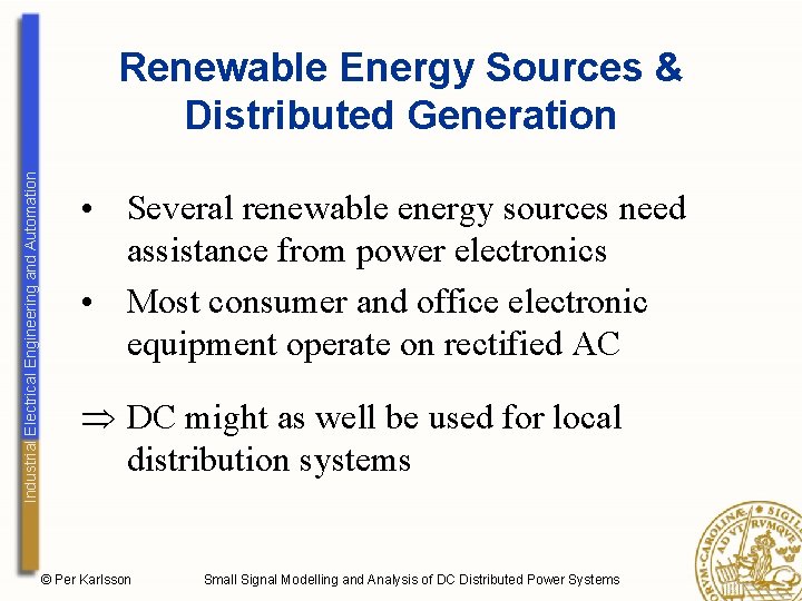
Industrial Electrical Engineering and Automation Renewable Energy Sources & Distributed Generation • Several renewable energy sources need assistance from power electronics • Most consumer and office electronic equipment operate on rectified AC DC might as well be used for local distribution systems © Per Karlsson Small Signal Modelling and Analysis of DC Distributed Power Systems
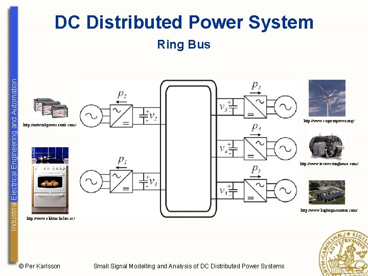
DC Distributed Power System Industrial Electrical Engineering and Automation Ring Bus http: //www. cogreenpower. org/ http: //networkpower. exide. com/ http: //www. tecowestinghouse. com/ http: //www. bigfrogmountain. com/ http: //www. elektro-helios. se/ © Per Karlsson Small Signal Modelling and Analysis of DC Distributed Power Systems
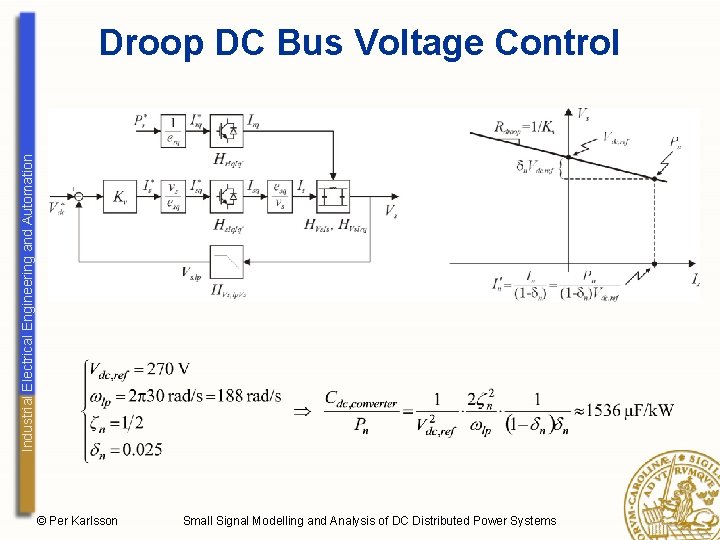
Industrial Electrical Engineering and Automation Droop DC Bus Voltage Control © Per Karlsson Small Signal Modelling and Analysis of DC Distributed Power Systems
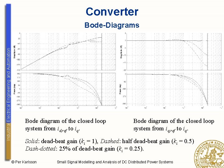
Converter Industrial Electrical Engineering and Automation Bode-Diagrams Bode diagram of the closed loop system from id, ref to iq. Bode diagram of the closed loop system from iq, ref to iq. Solid: dead-beat gain (ki = 1), Dashed: half dead-beat gain (ki = 0. 5) Dash-dotted: 25% of dead-beat gain (ki = 0. 25). © Per Karlsson Small Signal Modelling and Analysis of DC Distributed Power Systems
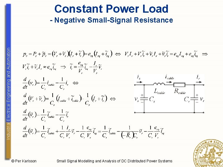
Constant Power Load Industrial Electrical Engineering and Automation - Negative Small-Signal Resistance © Per Karlsson Small Signal Modelling and Analysis of DC Distributed Power Systems
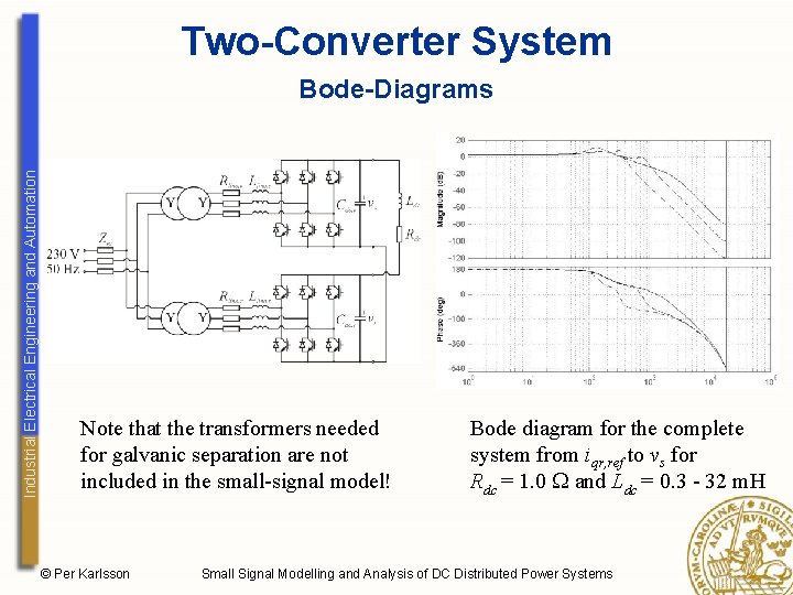
Two-Converter System Industrial Electrical Engineering and Automation Bode-Diagrams Note that the transformers needed for galvanic separation are not included in the small-signal model! © Per Karlsson Bode diagram for the complete system from iqr, ref to vs for Rdc = 1. 0 and Ldc = 0. 3 - 32 m. H Small Signal Modelling and Analysis of DC Distributed Power Systems
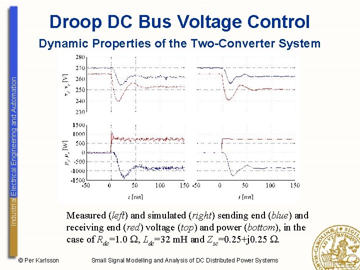
Droop DC Bus Voltage Control Industrial Electrical Engineering and Automation Dynamic Properties of the Two-Converter System Measured (left) and simulated (right) sending end (blue) and receiving end (red) voltage (top) and power (bottom), in the case of Rdc=1. 0 , Ldc=32 m. H and Zsc=0. 25+j 0. 25 . © Per Karlsson Small Signal Modelling and Analysis of DC Distributed Power Systems
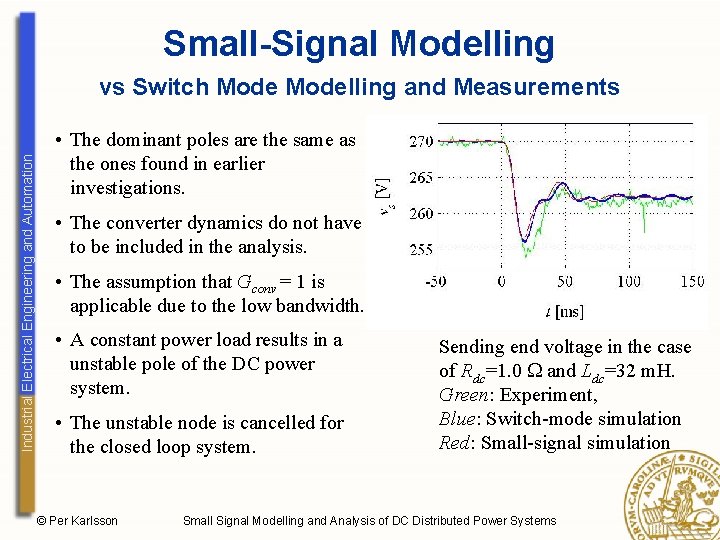
Small-Signal Modelling Industrial Electrical Engineering and Automation vs Switch Modelling and Measurements • The dominant poles are the same as the ones found in earlier investigations. • The converter dynamics do not have to be included in the analysis. • The assumption that Gconv = 1 is applicable due to the low bandwidth. • A constant power load results in a unstable pole of the DC power system. • The unstable node is cancelled for the closed loop system. © Per Karlsson Sending end voltage in the case of Rdc=1. 0 and Ldc=32 m. H. Green: Experiment, Blue: Switch-mode simulation Red: Small-signal simulation Small Signal Modelling and Analysis of DC Distributed Power Systems