Inlet and Outlet Manifolds and Plant Hydraulics In


- Slides: 45
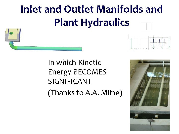
Inlet and Outlet Manifolds and Plant Hydraulics In which Kinetic Energy BECOMES SIGNIFICANT (Thanks to A. A. Milne)
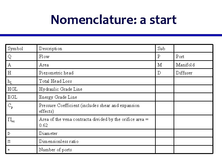
Nomenclature: a start Symbol Description Sub Q Flow P Port A Area M Manifold H Piezometric head D Diffuser h. L Total Head Loss HGL Hydraulic Grade Line EGL Energy Grade Line Cp Pressure Coefficient (includes shear and expansion effects) Pvc Area of the vena contracta divided by the orifice area = 0. 62 D Diameter P Dimensionless ratio n Number of ports
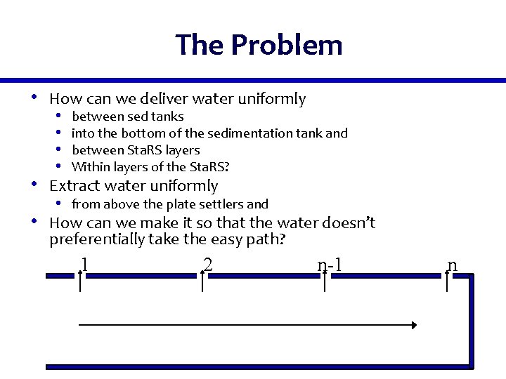
The Problem • How can we deliver water uniformly • between sed tanks • into the bottom of the sedimentation tank and • between Sta. RS layers • Within layers of the Sta. RS? • Extract water uniformly • from above the plate settlers and • How can we make it so that the water doesn’t preferentially take the easy path? 1 2 n-1 n
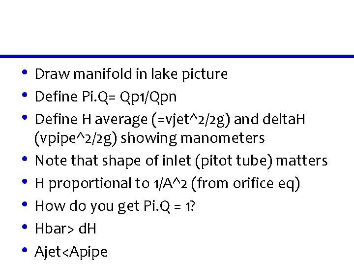
• Draw manifold in lake picture • Define Pi. Q= Qp 1/Qpn • Define H average (=vjet^2/2 g) and delta. H • • • (vpipe^2/2 g) showing manometers Note that shape of inlet (pitot tube) matters H proportional to 1/A^2 (from orifice eq) How do you get Pi. Q = 1? Hbar> d. H Ajet<Apipe
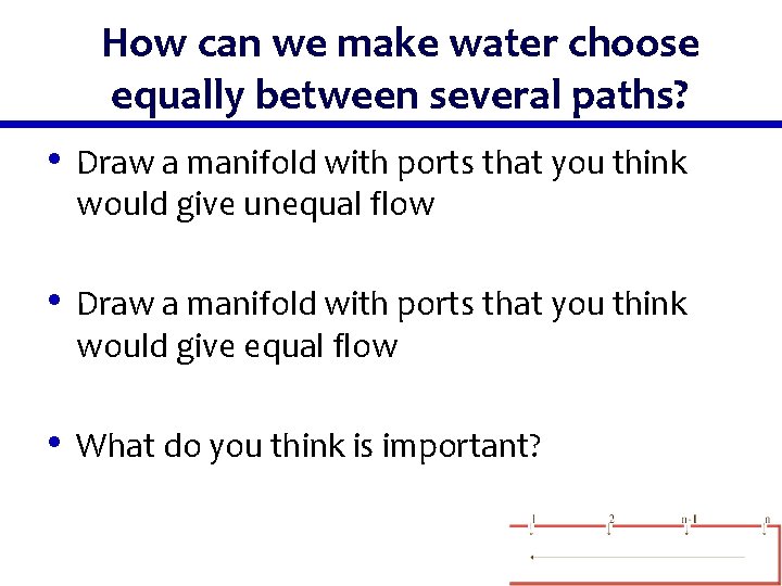
How can we make water choose equally between several paths? • Draw a manifold with ports that you think would give unequal flow • Draw a manifold with ports that you think would give equal flow • What do you think is important?
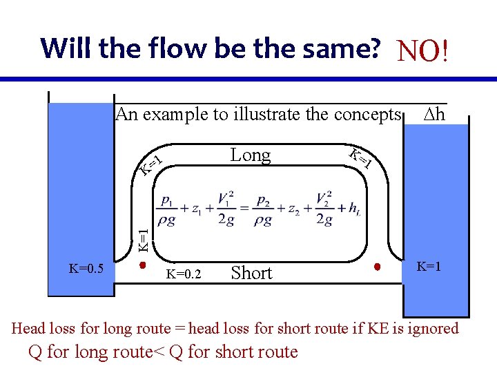
Will the flow be the same? NO! An example to illustrate the concepts Long =1 K=1 K h K=0. 5 K=0. 2 Short K=1 Head loss for long route = head loss for short route if KE is ignored Q for long route< Q for short route
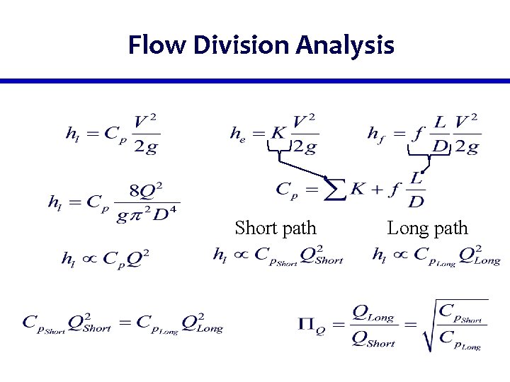
Flow Division Analysis Short path Long path
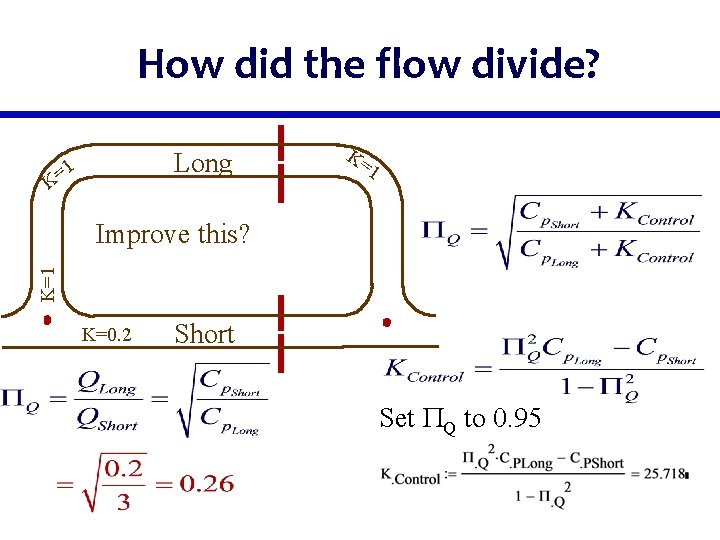
How did the flow divide? Long 1 = K K= 1 K=1 Improve this? K=0. 2 Short Set PQ to 0. 95
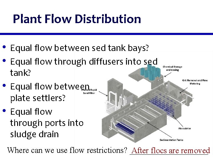
Plant Flow Distribution • Equal flow between sed tank bays? • Equal flow through diffusers into sed • • tank? Equal flow between plate settlers? Equal flow through ports into sludge drain Where can we use flow restrictions? __________ After flocs are removed
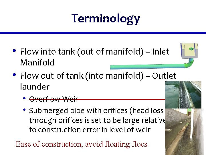
Terminology • Flow into tank (out of manifold) – Inlet • Manifold Flow out of tank (into manifold) – Outlet launder • Overflow Weir • Submerged pipe with orifices (head loss through orifices is set to be large relative to construction error in level of weir Ease of construction, avoid floating flocs
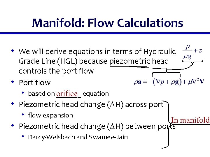
Manifold: Flow Calculations • We will derive equations in terms of Hydraulic • • • Grade Line (HGL) because piezometric head controls the port flow Port flow • based on _______ orifice equation Piezometric head change ( H) across port • flow expansion In manifold Piezometric head change ( H) between ports • Darcy-Weisbach and Swamee-Jain
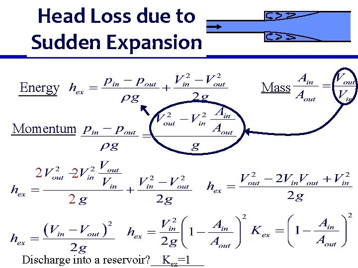
Head Loss due to Sudden Expansion Energy Mass Momentum 2 2 2 Discharge into a reservoir? _____ Kex=1
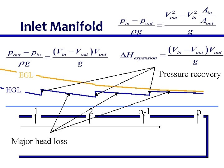
Inlet Manifold Pressure recovery EGL HGL 1 Major head loss 2 n-1 n
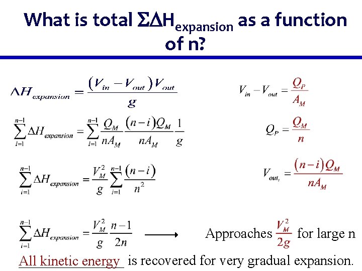
What is total SDHexpansion as a function of n? Approaches for large n ________ All kinetic energy is recovered for very gradual expansion.
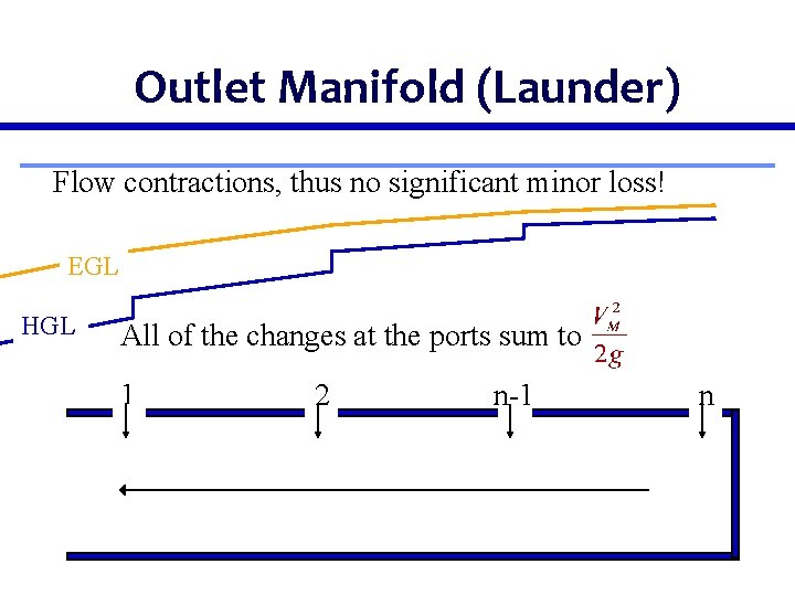
Outlet Manifold (Launder) Flow contractions, thus no significant minor loss! EGL HGL All of the changes at the ports sum to 1 2 n-1 n
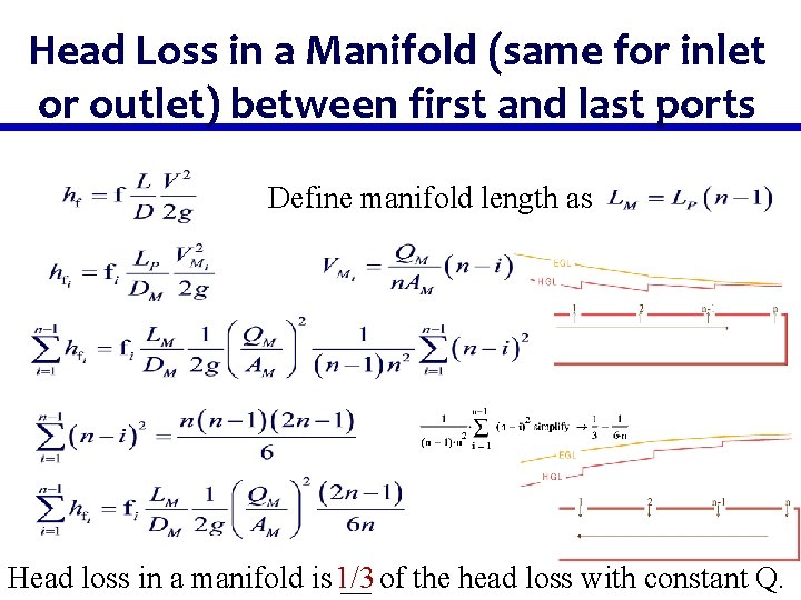
Head Loss in a Manifold (same for inlet or outlet) between first and last ports Define manifold length as Head loss in a manifold is 1/3 __ of the head loss with constant Q.
Change in Piezometric Head in an Outlet Manifold Total change in piezometric head Note: We have factored out the friction factor knowing that and thus f is not constant
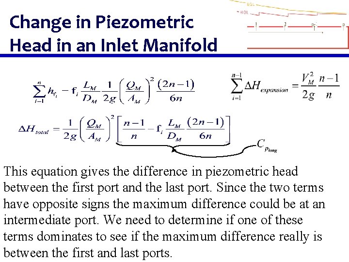
Change in Piezometric Head in an Inlet Manifold This equation gives the difference in piezometric head between the first port and the last port. Since the two terms have opposite signs the maximum difference could be at an intermediate port. We need to determine if one of these terms dominates to see if the maximum difference really is between the first and last ports.
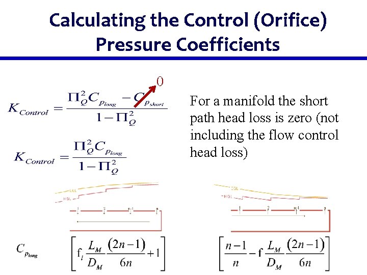
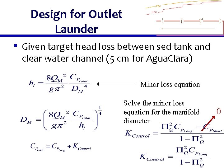
Calculating the Control (Orifice) Pressure Coefficients 0 For a manifold the short path head loss is zero (not including the flow control head loss)
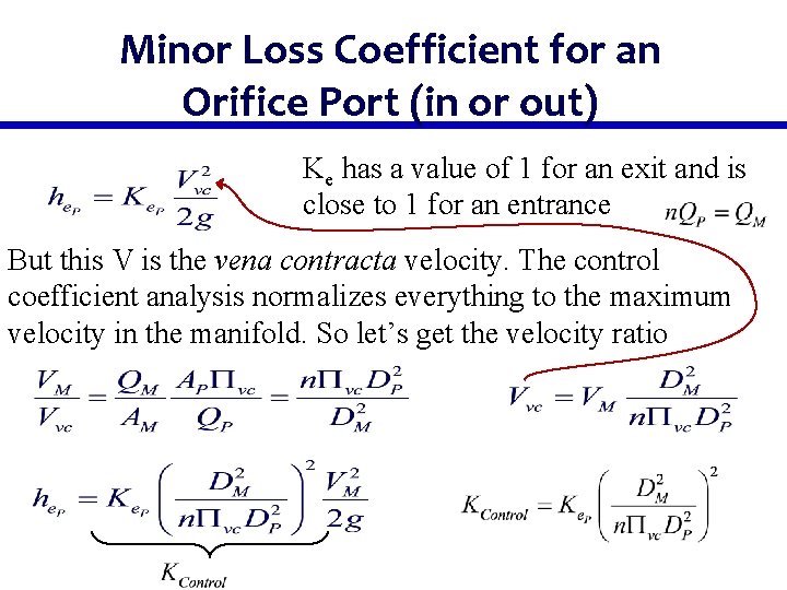
Minor Loss Coefficient for an Orifice Port (in or out) Ke has a value of 1 for an exit and is close to 1 for an entrance But this V is the vena contracta velocity. The control coefficient analysis normalizes everything to the maximum velocity in the manifold. So let’s get the velocity ratio
Solution Path • The length of the manifold will be • • determined by the plant geometry The spacing of the ports will be set by other constraints We need to determine the diameter of the manifold and the diameter of the ports
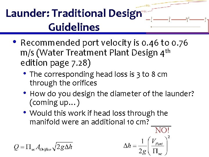
Launder: Traditional Design Guidelines • Recommended port velocity is 0. 46 to 0. 76 m/s (Water Treatment Plant Design 4 th edition page 7. 28) • The corresponding head loss is 3 to 8 cm • • through the orifices How do you design the diameter of the launder? (coming up…) Would this work if head loss through the manifold were an additional 10 cm? _____ NO!
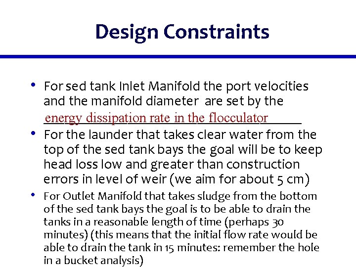
Design Constraints • For sed tank Inlet Manifold the port velocities • and the manifold diameter are set by the ___________________ energy dissipation rate in the flocculator For the launder that takes clear water from the top of the sed tank bays the goal will be to keep head loss low and greater than construction errors in level of weir (we aim for about 5 cm) • For Outlet Manifold that takes sludge from the bottom of the sed tank bays the goal is to be able to drain the tanks in a reasonable length of time (perhaps 30 minutes) (this means that the initial flow rate would be able to drain the tank in 15 minutes: remember the hole in a bucket analysis)
Design for Outlet Launder • Given target head loss between sed tank and clear water channel (5 cm for Agua. Clara) Minor loss equation Solve the minor loss equation for the manifold diameter 0
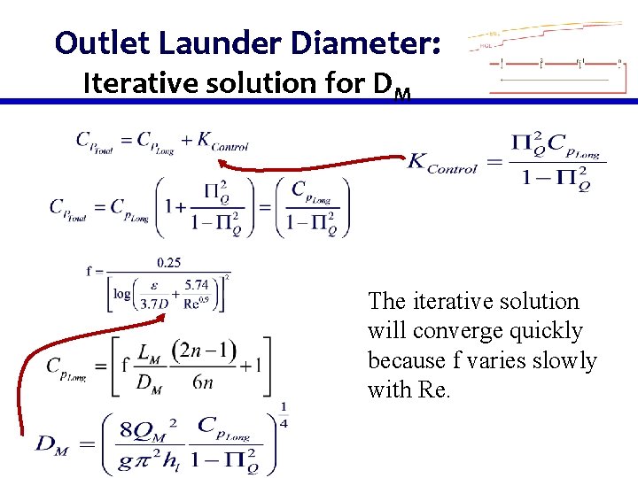
Outlet Launder Diameter: Iterative solution for DM The iterative solution will converge quickly because f varies slowly with Re.
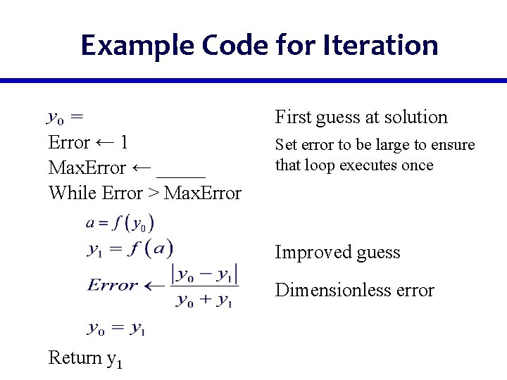
Example Code for Iteration First guess at solution Error ← 1 Max. Error ← _____ While Error > Max. Error Set error to be large to ensure that loop executes once Improved guess Dimensionless error Return y 1
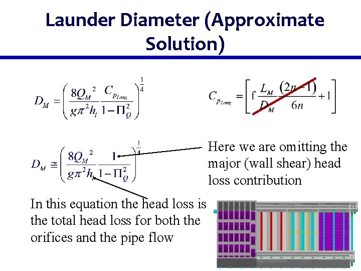
Launder Diameter (Approximate Solution) Here we are omitting the major (wall shear) head loss contribution In this equation the head loss is the total head loss for both the orifices and the pipe flow
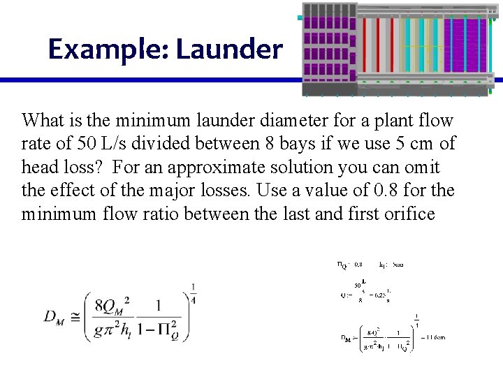
Example: Launder What is the minimum launder diameter for a plant flow rate of 50 L/s divided between 8 bays if we use 5 cm of head loss? For an approximate solution you can omit the effect of the major losses. Use a value of 0. 8 for the minimum flow ratio between the last and first orifice
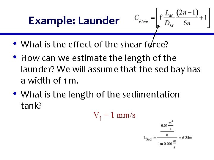
Example: Launder • What is the effect of the shear force? • How can we estimate the length of the • launder? We will assume that the sed bay has a width of 1 m. What is the length of the sedimentation tank? V↑ = 1 mm/s
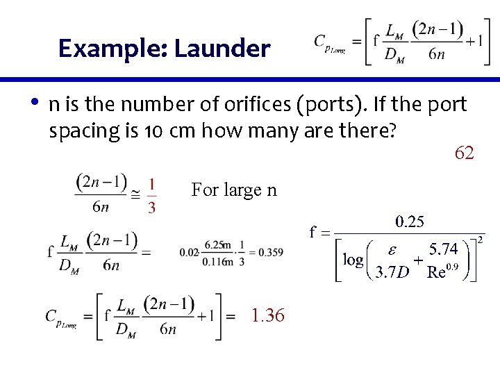
Example: Launder • n is the number of orifices (ports). If the port spacing is 10 cm how many are there? For large n 1. 36 62
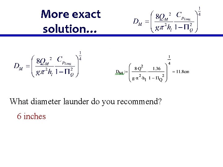
More exact solution… What diameter launder do you recommend? 6 inches
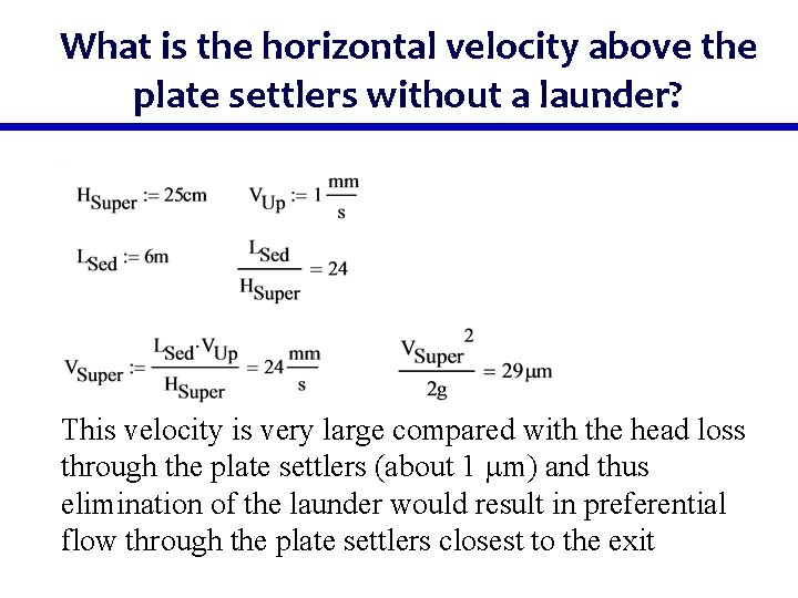
Why is the launder diameter so large? • (50 L/s /9) launder of 6 inches • The head loss in the launder is small and it would be • • • tempting to use a smaller pipe Why is such a large pipe necessary? _______ Equal orifice flow Why do we even need a launder pipe? For uniform flow distribution between (and within) ______________________ plate settlers ______ What is the max velocity above the plate settlers given a 1 m wide tank, 25 cm of water above the plates, a single launder? _____ 2 mm/s
What is the horizontal velocity above the plate settlers without a launder? This velocity is very large compared with the head loss through the plate settlers (about 1 mm) and thus elimination of the launder would result in preferential flow through the plate settlers closest to the exit
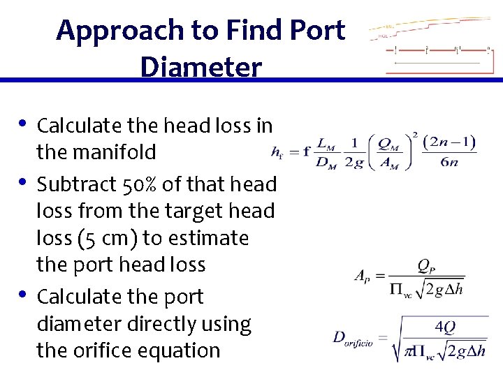
Approach to Find Port Diameter • Calculate the head loss in • • the manifold Subtract 50% of that head loss from the target head loss (5 cm) to estimate the port head loss Calculate the port diameter directly using the orifice equation
What about Inlet Manifold Design? • Total head loss is not a constraint (it will be • • • VERY small) Energy dissipation rate at the inlet of the manifold determines the manifold diameter Energy dissipation rate at the inlet to the diffuser pipes will set the diffuser diameter Available pipe sizes for inlet manifold and for the diffusers is a constraint
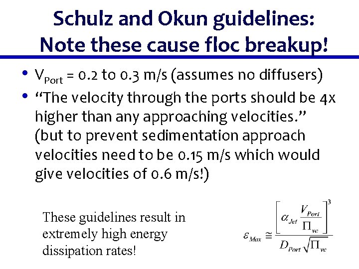
Schulz and Okun guidelines: Note these cause floc breakup! • VPort = 0. 2 to 0. 3 m/s (assumes no diffusers) • “The velocity through the ports should be 4 x higher than any approaching velocities. ” (but to prevent sedimentation approach velocities need to be 0. 15 m/s which would give velocities of 0. 6 m/s!) These guidelines result in extremely high energy dissipation rates!
Schulz and Okun famous quote… “In practice, one can rarely meet all four basic requirements because they conflict with one another; thus a reasonable compromise must be attained. ” Conclusion of inlet design for sedimentation tanks. Page 135 in Surface Water Treatment for Communities in Developing Countries
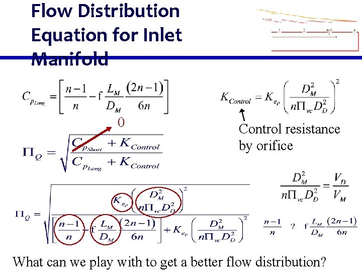
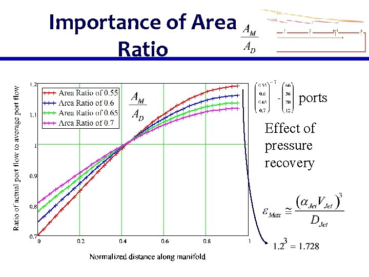
Flow Distribution Equation for Inlet Manifold 0 Control resistance by orifice What can we play with to get a better flow distribution?
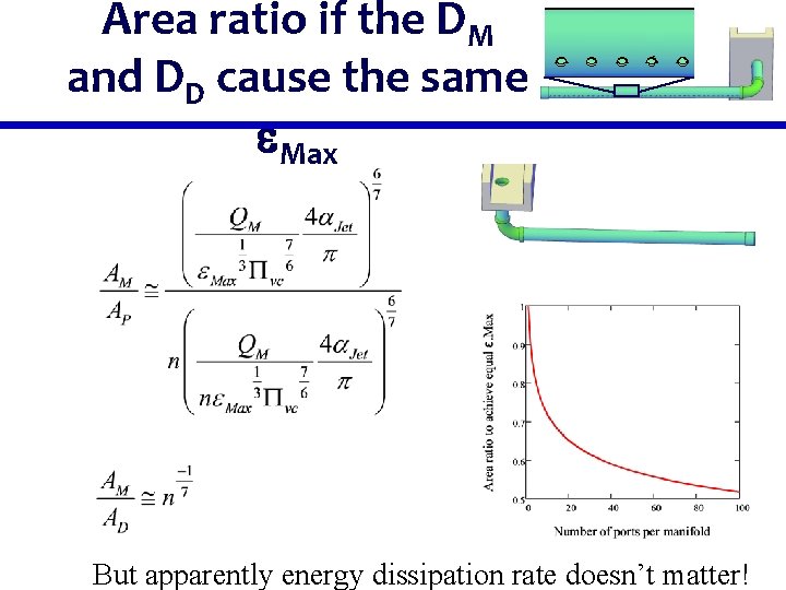
Area ratio if the DM and DD cause the same e. Max But apparently energy dissipation rate doesn’t matter!
Importance of Area Ratio ports Effect of pressure recovery
One more Issue: Vena Contracta with High Velocity Manifold • The vena contracta at each port must be • • much more pronounced (small Pvc) when the velocity inside the manifold is high. If the vena contracta, Pvc, is smaller, then the velocities are higher and the energy dissipation rate is higher. This requires further investigation
Manifold Conclusions • Outlet manifolds (launder) require an iterative • design to get the manifold diameter Inlet manifold design has complex constraints… • Avoid breaking flocs • Don’t let flocs settle (ignore if ports are on bottom) • Distribute flow uniformly • Eliminate horizontal velocity in the sed tank • Produce jets to resuspend flocs to form floc blanket
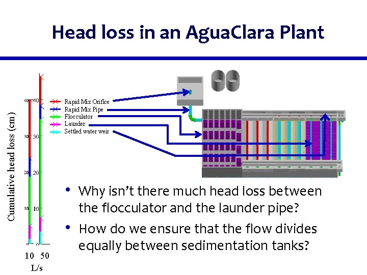
Head loss in an Agua. Clara Plant Cumulative head loss (cm) Rapid Mix Orifice Rapid Mix Pipe Flocculator Launder Settled water weir • Why isn’t there much head loss between • 10 50 L/s the flocculator and the launder pipe? How do we ensure that the flow divides equally between sedimentation tanks?
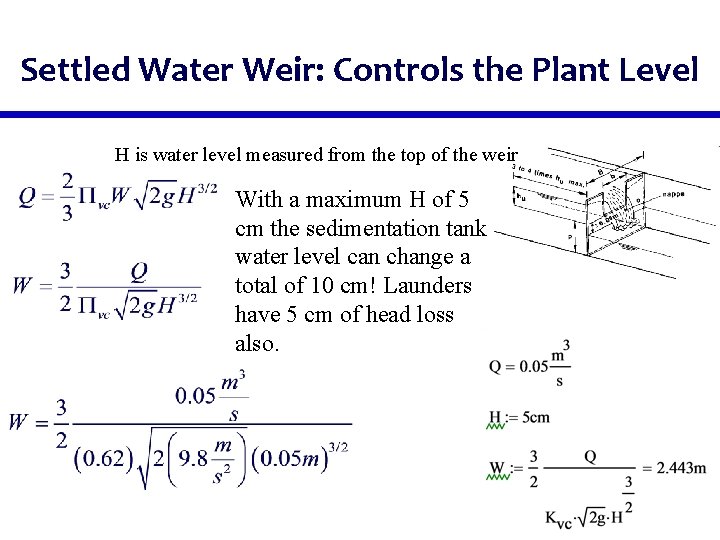
Settled Water Weir: Controls the Plant Level H is water level measured from the top of the weir With a maximum H of 5 cm the sedimentation tank water level can change a total of 10 cm! Launders have 5 cm of head loss also.
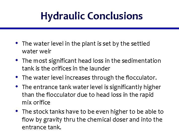
Hydraulic Conclusions • The water level in the plant is set by the settled • • water weir The most significant head loss in the sedimentation tank is the orifices in the launder The water level increases through the flocculator. The entrance tank water level is significantly higher than the flocculator due to head loss in the rapid mix orifice The stock tanks have to be even higher to be able to flow by gravity thru the chemical doser and into the entrance tank.