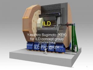
ILD Status and future Yasuhiro Sugimoto KEK 20121220


- Slides: 35

ILD Status and future Yasuhiro Sugimoto (KEK) 2012/12/20 1

Events on ILD in 2012 • Apr. 23 -27: KILC 2012 @Daegu – IDAG interview – ILD meeting • May 15 -16: ILC PAC @Fermilab – ILD status report by Graham Wilson • May 23 -25: ILD Workshop @Kyushu Univ. • Sep. 28: ILD DBD 0 th draft sent to IDAG – Many holes, particularly in physics analysis section • Oct. 22 -26: LCWS 2012 @UTA – IDAG review – ILD meeting (discussed mainly physics analysis) • Nov. 30: Submission of ILD DBD draft – Draft is quite complete – Results of benchmark analysis is still preliminary – Delay in finalization of the numbers of costing • Dec. 13 -14: ILC PAC @KEK – ILD DBD report by Y. S. 2

ILD DBD 3

4

Draft as of Nov. 30 • ILD benchmark analysis is still on-going • All the numbers may change by the end of January 2013 • Costing section is not complete 5

PAC meeting at KEK 6

PAC meeting • PAC meeting was held at KEK 13 -14 December • Web page – http: //ilcagenda. linearcollider. org/conference. Display. p y? conf. Id=5843 • ILD made the presentation which summarizes the ILD DBD • Some new numbers which were not included in the Nov. 30 draft were shown – Post-LOI analyses – Some of 1 Te. V benchmark results • It became clear that coordination with Si. D is necessary 7

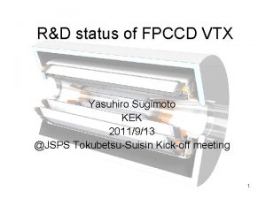
ILD Muon system/yoke Solenoid coil HCAL ECAL TPC Lumi. CAL Beam. CAL FCAL LHCAL FTD SIT VTX 8

ILD baseline Sensor options for baseline design FPCCD Alternative VTX CMOS DEPFET SIT False doublesided strip FTD 1 -2 CMOS FTD 3 -7 False doublesided strip TPC GEM Micro. MEGAS Pixel readout ECAL W-Si pad W-Scintillator strip W-Pixel HCAL Analog (Scintillator) Semi digital (RPC) FCAL W-Si / Ga. As W-Si / Diamond Muon Scintillator strip Double-sided strip FPCCD DEPFET Mechanical structure is also different RPC 9

LOI benchmark ECM (Ge. V) 250 500 Observable Precision Comments Post LOI analysis s(e+e- Zh) 2. 5% Model independent mh 32 Me. V Model independent mh 27 Me. V Model dependent Br(h bb) 2. 7%* Br(h cc) 12% 7. 3%* Br(h gg) 29% Includes 2. 5% of s(Zh) 8. 9%* Br(h tt) 4. 9% Br(h WW*) 8. 6% s(e+e- c 1+c 1 -) 0. 6% s(e+e- c 20) 2. 1% m(c 1+) 2. 4 Ge. V m(c 20) 0. 9 Ge. V m(c 10) 0. 8 Ge. V From kinematical edges Two masses (LSP and c 1+/c 20) are fitted simultaneously * http: //arxiv. org/abs/ar. Xiv: 1207. 0300 H. Ono, Akiya Miaymoto 10

LOI benchmark ECM (Ge. V) 500 500 1000 Observable Precision Comments s(e+e- tt) 0. 29% qtt>178 degree At. FB 0. 0025 qtt>178 degree Pt 0. 007 Excluding a 1 n s(e+e- tt) 0. 4% (bqq) only mt 40 Me. V Fully hadronic only mt 30 Me. V + semi-hadronic Gt 27 Me. V Fully hadronic only Gt 22 Me. V + semi-hadronic AFB 0. 0079 Fully hadronic only s(e+e- m. L+m. L-) 2. 5% m(m. L) 0. 5 Ge. V m(t 1) 0. 1 Ge. V⊕ 1. 3 s. LSP a 4 -1. 4< a 4 <1. 1 a 5 -0. 9< a 5 < 0. 8 SPS 1 a’ (smuon) SPS 1 a’ (stau) Strong EWSB in WW scattering 11

1 Te. V benchmark • e+e- nnh – Higgs production cross section is larger than 250 Ge. V – Luminosity is larger than 250 Ge. V – Higgs mm channel can be measured Decay s. Br accuracy mode (500 fb-1, -0. 8, +0. 2) Comments y r a n i m i l e r P bb 0. 4% cc 5% gg 4% WW* 3% mm ? ? Fully hadronic mode only 12

1 Te. V benchmark • e+ e - t t h – Fully hadronic mode (8 jets, no isolated lepton) and semileptonic mode (6 jets + 1 isolated lepton) were used – Main background: ttbb, tt. Z, and tt – Multivariable analysis technique is effective to reduce the background – Preliminary result on accuracy of top Yukawa coupling with 500 fb-1 (+0. 8, -0. 2) and 500 fb-1 (-0. 8, +0. 2) • 7. 0% for semi-leptonic mode • 6. 5% for hadronic mode • 4. 8% for combined data 13

Other physics processes • Higgs self coupling – Zhh final state at 500 Ge. V • 27% accuracy in Zhh cross section = 44% accuracy in l with 2 ab-1 – nnhh final state at 1 Te. V • 17% accuracy in l with 2 ab-1 (Fast simulation) • Full simulation study on going • Further t t study – At. FB by semi-leptonic decay mode • 1% measurement can be done – Athel (helicity asymmetry) measurement – t t at threshold: measurement of mt and as 14

Discussion at PAC 15

SUSY mass • There is large difference of the accuracy of SUSY masses between Si. D and ILD in LOIs • We discussed this issue and we understand the reason • We still have to discuss how to present it in DBD Tim will contact Jenny to discuss it 16

Higgs branching ratio at 1 Te. V • Si. D knows the unbelievable accuracy in Higgs branching ratio at 1 Te. V is wrong • They will re-evaluate the accuracy 17

Beam polarization • Si. D and ILD should use same luminosity for each polarization combination tth WW nnh L (-80%, +20%) L (+80%, -20%) Si. D ILD 1000 fb-1 0 4. 1% NA 500 fb-1 4. 6% 4. 8% 500 fb-1 0. 17% (e-) In progress ? 1000 fb-1 500 fb-1 (500 fb-1) Results shown • If possible, we should give the results of both cases (1 ab-1 with preferable polarization and 500 fb-1 each) Gives a guideline for running plan at 1 Te. V 18

BR summary table • IDAG suggested to make one table which summarizes precision of branching ratios of all accessible decay channels by ILC • The table would be placed either in the Physics volume or in the introduction chapter of DBD • Michael Peskin and Keisuke Fujii will discuss how to make it 19

All summary table • In PEB meeting yesterday, Sakue-san mentioned that the directorate is considering to make a table summarizing all of the physics analysis results, and put it in the summary chapter 20

Review report by IDAG at PAC 21

Summary of IDAG 22

23

24

25

26

What’s next for DBD • We still have a lot of things to do for benchmark analyses – Finalize 1 Te. V benchmark study and fix the results through internal review by middle of January (before Si. D WS 16 -18 Jan. 2013? ) – Revise the description on LOI benchmark analysis to include post-LOI analyses – Discuss and coordinate with Si. D to make the whole DBD self-consistent – Collaborate with RD and physics common task group to make summary tables 27

What’s next for DBD • Critical reading of the draft is necessary – by “readers” group – by JSB(? ) • Costing has to be finalized 28

ILD activity after DBD • We have to define the goal of next few years (Proposal? , TDR? , …) – The goal will be set officially by the LCB – But the physics/detector community should give the input to the LCB • Discussion has just started – Serious discussion at ECFA 2013 meeting in May – There may be some discussion at AIDA meeting in April @Frascati (Italian participation to ILD? ) • Anyway, detector R&D (particularly in engineering aspects) has to be continued towards “construction ready” design of ILD • Physics study which have not been covered in DBD should be done 29

ILD activity after DBD • One possible roadmap 12 Due process DBD Off-site R&D 13 14 15 Proposals 16 17 18 20 21 22 23 24 25 Detector assembly Comm issioni ng Ready 200 800 TDRs Sub-detector construction On surface Assembly hall Underground Access tunnel / Cavern Physicists on site* 19 Detector pre-assembly 100 200 400 * {100 (Laboratory personnel) + 300 (Visitors)}x 2 detectors = 800 – If we wish to start physics run in 2025, we have to start writing our proposal in 2014 30

Backup slides 31

1 Te. V benchmark • e+ e - W + W – Precise measurement of beam polarization – Two methods • Modified Blondel scheme: (+, +), (+, -), (-, +), (-. -) data required • Angular distribution of W Analysis not finished yet Blondel method 32

LOI-DBD common benchmark • We used e+e- t t channel for the comparison between LOI and DBD analysis @500 Ge. V • Forward-backward asymmetry is determined by hadronic decay mode • Vertex charge determination is needed good benchmark for vertex detector/finding • Results with 500 fb-1, P(e-, e+)=(-0. 8, +0. 3) : – At. FB = Coming soon (DBD) – At. FB = 0. 334± 0. 0079 (LOI) 33

Cost • Progress since LOI – Development of technological prototypes close to final design Information on costs – Integration of whole detector has been studied – New agreement on methodology and unit costs of cost drivers • ILD current cost evaluation – Study is on-going – ~500 MILCU including manpower 34

Summary of PAC presentation • Detailed baseline design of ILD based on validated detector technologies has been presented • Compared with LOI, more realistic design including support structure, cables, other services, and dead material has been made • Although the material budget has been increased, better detector performance than LOI has been obtained thanks to the improvement of software tools and analysis methods • New benchmark processes at 1 Te. V have been studied with 2 -photon process background overlaid (We still need few weeks to finalize the results, though) • We still need detector R&D, particularly in the engineering aspect, after completion of DBD 35
 Dr csiki vanda
 Yasuhiro okada
 Ild nurse
 Allergies icd 10
 Ild
Ild Ild.deb
 Ild vs led
 Ild
Ild Future perfect and future continuous examples
 Future perfect simple continuous
 Future perfect and future continuous examples
 Tenses
 Future plans and finished future actions
 Future continuous
 Future continuous and future perfect objasnjenje
 Async-std
 Kako kek
 Kek.manet
 Kek tools
 üzümlü kek atom modeli
 Kek
Kek Kek
Kek Kako kek
 Kek manet
 Premo kek
 Bob kek
 Kek 13
 Latihan termokimia tingkatan 3
 Kek gem
 Kek
Kek Picasso a vak ember élete
 Kek kh
 Kek n
Kek n Kek kds
 Kako kek
 Futaba kek
