KEK IR status Shuji Tanaka KEK DEPFET workshop


 • Mockup")
")
 equivalent stress :Max 176 MPa Deformation :Max 6. 7 mm equivalent stress")

 test pieces 2,")

 BPM move to QC side Japan group will take")
 will be discussed")
 We start discussion about bracket of beam pipe now.")


")
 Main block Long pipe(M 8) Clamp( M 8ナット) Clamp(穴径φ8. 2) SVD could")


 http: //kds. kek. jp/conference. Display. py?")


 • The baseline of BEAST II operation is no collision of")


- Slides: 37
KEK IR status Shuji Tanaka KEK DEPFET workshop 2011/2/7 -9 1
Latest design of IP chamber Straight section Kohriki Very simple Be structure • Cooling route is change (back) to feed forward type – Worry for cooling dead region (end point of IP) • Forward manifold is placed on crotch part • Be part is only within “Physics window”. – -> other region can add materials (ex 100 um Au for SR) • Be structure is simple barrel type -> very cheap 2
Narrow Space issue between PXD and IP At present, it seems that we can avoid space problem by optimizing beam pipe shape( still should pay attention) 3
Cooling test mockup Nakayama
Connection technology choice Brazing EBW or Brazing Be: 1 M yen EBW Weak point by EBW HIP: Hot lsostatic Pressing EBW: Electron Beam Welding Be: 34 M yen Pros. : very simple structure and cheap Be part Cons. : Be-SUS region face with vacuum part 5
Tests before IP chamber production • Mechanical analysis of beam pipe (KEK) • Mockup production of crotch part by Al. – To evaluate howto make sawtooth structure • Ta-SUS HIP welding test production – Brazing test – EBW test -> to see thermal effects of pipe (deformation, vacuum sealing) • Be part test production (NGK insulators Co. Lid. ) – Check the precision of structure – -> cut into some pieces • Be-SUS Connection test next year (before next summer) 6
Mechanical analysis Koike Deformation by self weight equivalent stress :Max 22 MPa (support point) Deformation:Max 0. 0082 mm Support point : End of flange and Near IP +/- 350 mm from IP equivalent stress :Max 1. 2 MPa 拡大
Mechanical analysis (cantilever) equivalent stress :Max 176 MPa Deformation :Max 6. 7 mm equivalent stress Max
Mechanical analysis Self weight + coolant pressure 10 atm IP region equivalent stress :Max 93 MPa 変位:Max 0. 014 mm Deformation:Max ~ 0. 011 mm Be Equivalent stress:Max 42 MPa
Ta-SUS HIP welding test production 1, make Ta-SUS HIP (diffusion bonding) test pieces 2, applying thermal stress by EBW 3, check the vacuum level and mechanical deformation (This procedure will be used on joining , inner and outer pipes)
Mockup production of crotch part by Al In order to evaluate the production procedures how to cut inside(Saw tooth) of crotch part beam pipe. ->will be finish before the end of Mar.
IR design (top view: KEK) BPM move to QC side Japan group will take care and assemble SVD 3 rd layer KEK: CDC design, Endflange, Beam pipe SVD endring, SVD 3 rd
SVD Mechanics Space Requirement SVD Two types of design(Vienna and KEK) will be discussed on next B 2 GM 18 November 2010 Immanuel Gfall (HEPHY Vienna) 13
IR design (side view) We start discussion about bracket of beam pipe now.
Space allocation of inner tracker Heavy Metal support End ring CFRP 1 mm Total weight will be ~100 kg End flange (Ta? ) Some suspension IP flange position Structure for beam pipe
End-Flange prototyping This bracket has a role of shielding Material: Heavy Metal (>1. 5 cm t) 16
SVD installation
SVD installation Kohriki
SVD installation (mechanics)
QCS-SVD-joint Pin(φ10) Main block Long pipe(M 8) Clamp( M 8ナット) Clamp(穴径φ8. 2) SVD could be kept by CDC by releasing Pin. (to be Independent with QC cryostat) 20101202 Kohriki 20
SVD Mechanical Analysis equivalent stress:Max 25 MPa Deformation:Max 0. 015 mm Mechanical distortion is enough small =SVD can keep structure by sustain each end 最大主応力:Max 15 MPa
SVD+IR installation procedure Find a solution for installing this IR structure. ~ Establish a reasonable procedure to connect vacuum chamber flanges. • Belle II is fully equipped. • IP chamber is supported by SVD frame. • SVD is supported by CDC. • QCS cryostats can move out. Connection flanges for vacuum chambers. Top view Some work spaces to access flanges. It will be possible to make use of these spaces. Little work space to access flanges. It is impossible to connect flanges in this configuration.
DISCUSSION ITEMS 23
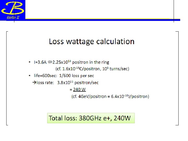
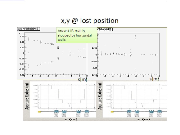
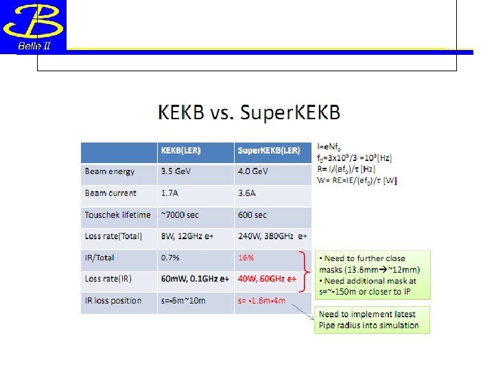
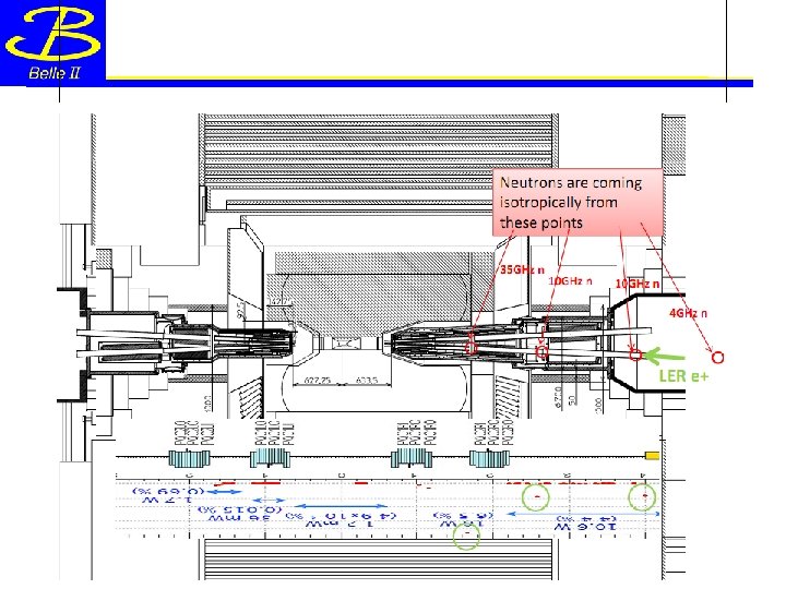
Touschek BG estimation ( High energy neutron BG) http: //kds. kek. jp/conference. Display. py? conf. Id=6541
Ohnishi
Nakayama
Photonuclear peak
BEAST Operation (idea) • The baseline of BEAST II operation is no collision of beams, because of no Belle magnetic field. • Preparing new solenoid magnet to study BG level. (just idea) – Inner diameter ~60 cm – setup some radiation monitors – Need more cost ~ 1 Oku-en. – Difficulty shaping outer magnetic field (need return yoke? ) • KEKB group prefer to use Belle detector because of easiness of operation-> schedule will delay 1~1. 5 years
CO 2 cooling We had meeting with KEK cryogenic group about CO 2 cooling last month. They said: The cooling power of CO 2 system should be less than 3 Reitoutons( Japanese unit: it means pumping power should be less than 7. 5 k. W, and parallel ). If our system satisfy this requirement, there are no limitation for system production. If our system power will be higher than requirement, we need permission for each sub-parts. KEK group agree to maintain CO 2 system on Belle II operation, then it is better to start discussing about our system outline and schedule (Next B 2 GM).
Summary • The basic design of beam optics is finished – Inner structure of beam pipe is almost fixed (on schedule). • Still need Sawtooth optimization (beam test on next year) – Space assignment with PXD and SVD should be discuss in detail (in particular near 3 rd layer SVD) – Mechanical analysis estimation and connection test (IP) (OK) • Vacuum test on Be-SUS connection (within 1 year) – Mockup production (crotch part) – BEASTII and neutron simulation discussion are started – There are still some open issues (cabling, cooling) 34
Schedule • ~2011 Mar. – Mechanical design and joint test – Mockup production of crotch part • 2011– Mechanical design fix (Ridge(Sawtooth), cooling…) – Optimizing production procedure – Service space allocation – SR beam test (May and July: X-ray 5 -50 ke. V) • 2012 – Beam pipe production • 2013 – IR Assembly 35
bkup 36
General IR design based on Nano-beam scheme Beam energy was changed to 7 x 4 Ge. V (vertical beam size: 940 nm>59 nm) To save the short lifetime for LER(Touschek effect) Crossing angle 83 mrad To make QCS magnets closer to IP Separated final quadrupole magnets Use both of superconducting and permanent magnets Boundary conditions between accelerator and detector are same as the present Angle of 41. 5 mrad between HER orbit and Belle To save vertical emittance increase by anti-solenoid fringe fields 37