CW Cryomodules KEK injector cryomodule Eiji Kako KEK
- Slides: 17
CW Cryomodules; KEK injector cryomodule Eiji Kako (KEK, Japan) TTC at Cornell, 2013 June 14 1
OUTLINE 1. c. ERL injector cryomodule 2. Cryomodule assembly in clean room 3. Cryomodule assembly in clean booth 4. Installation in beam line 5. Low power RF tests 6. High power RF tests 7. Static and dynamic heat loads 8. Beam operation 9. Summary Eiji Kako (KEK, Japan) TTC at Cornell, 2013 June 14 2
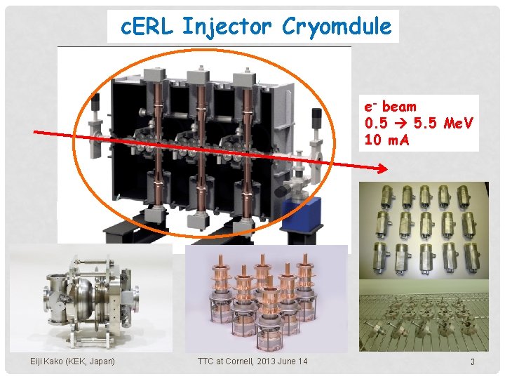
c. ERL Injector Cryomdule e- beam 0. 5 5. 5 Me. V 10 m. A Eiji Kako (KEK, Japan) TTC at Cornell, 2013 June 14 3
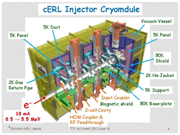
c. ERL Injector Cryomdule Vacuum Vessel 5 K Duct 5 K Panel 80 K Shield 2 K He Jacket 2 K Gas Return Pipe e- 10 m. A 0. 5 → 5. 5 Me. V 4 Eiji Kako (KEK, Japan) 5 K Support Input Coupler Magnetic shield 2 -cell Cavity 80 K Base-plate HOM Coupler & RF Feedthrough TTC at Cornell, 2013 June 14 4
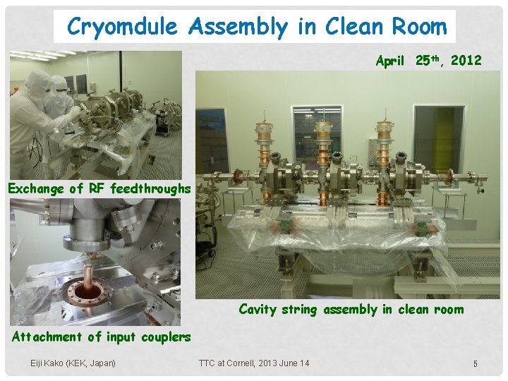
Cryomdule Assembly in Clean Room April 25 th, 2012 Exchange of RF feedthroughs Cavity string assembly in clean room Attachment of input couplers Eiji Kako (KEK, Japan) TTC at Cornell, 2013 June 14 5
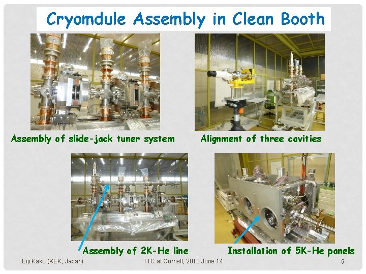
Cryomdule Assembly in Clean Booth Assembly of slide-jack tuner system Alignment of three cavities Assembly of 2 K-He line Eiji Kako (KEK, Japan) TTC at Cornell, 2013 June 14 Installation of 5 K-He panels 6
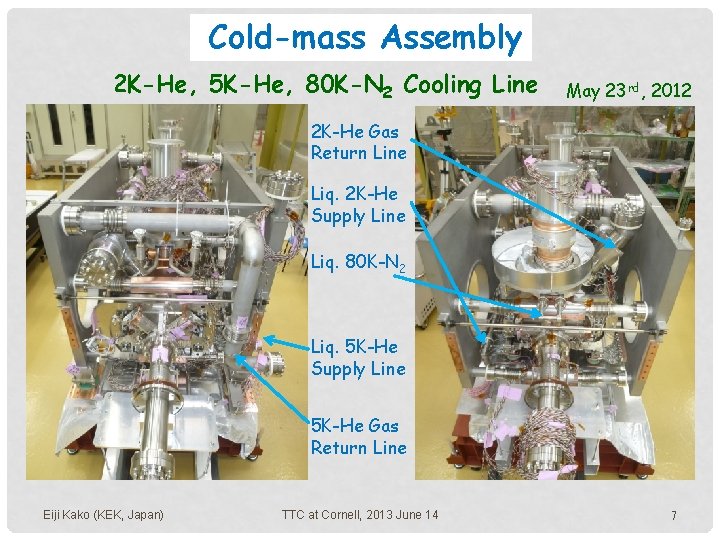
Cold-mass Assembly 2 K-He, 5 K-He, 80 K-N 2 Cooling Line May 23 rd, 2012 2 K-He Gas Return Line Liq. 2 K-He Supply Line Liq. 80 K-N 2 Liq. 5 K-He Supply Line 5 K-He Gas Return Line Eiji Kako (KEK, Japan) TTC at Cornell, 2013 June 14 7
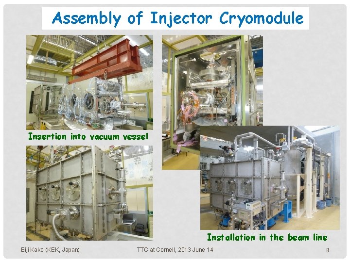
Assembly of Injector Cryomodule Insertion into vacuum vessel Installation in the beam line Eiji Kako (KEK, Japan) TTC at Cornell, 2013 June 14 8
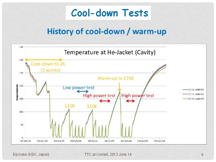
Cool-down Tests Eiji Kako (KEK, Japan) TTC at Cornell, 2013 June 14 9
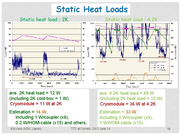
Static Heat Loads Static heat load ; 2 K Static heat load ; 4. 2 K ave. 2 K heat load = 12 W (including 2 K cold-box = 1 W) Cryomodule = 11 W at 2 K ave. 4. 2 K heat load = 48 W (including 2 K heat load = 12 W) Cryomodule = 36 W at 4. 2 K Estimation = 14 W, including 1 W/coupler (x 6), 0. 2 W/HOM-cable (x 15) and others. Estimation = 33 W, including 3 W/coupler (x 6), 1 W/HOM-cable (x 15). Eiji Kako (KEK, Japan) TTC at Cornell, 2013 June 14 10
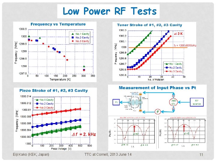
Low Power RF Tests Eiji Kako (KEK, Japan) TTC at Cornell, 2013 June 14 11
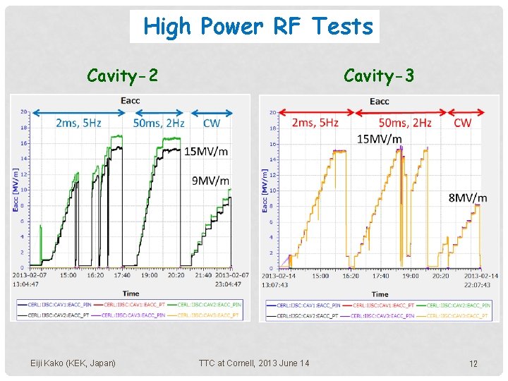
High Power RF Tests Cavity-3 Cavity-2 Eiji Kako (KEK, Japan) TTC at Cornell, 2013 June 14 12
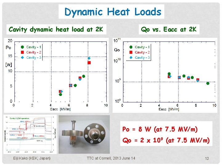
Dynamic Heat Loads Cavity dynamic heat load at 2 K Qo vs. Eacc at 2 K Po = 8 W (at 7. 5 MV/m) Qo = 2 x 10⁹ (at 7. 5 MV/m) Eiji Kako (KEK, Japan) TTC at Cornell, 2013 June 14 13
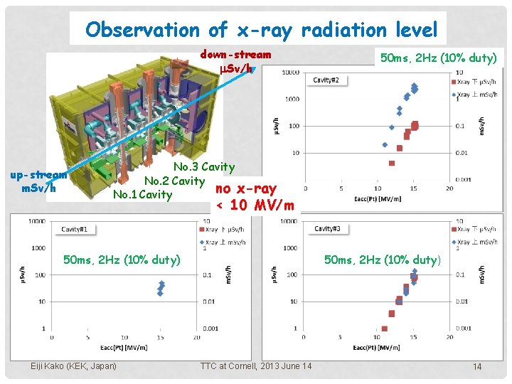
Observation of x-ray radiation level down-stream m. Sv/h up-stream m. Sv/h 50 ms, 2 Hz (10% duty) No. 3 Cavity No. 2 Cavity no x-ray No. 1 Cavity < 10 MV/m 50 ms, 2 Hz (10% duty) Eiji Kako (KEK, Japan) 50 ms, 2 Hz (10% duty) TTC at Cornell, 2013 June 14 14
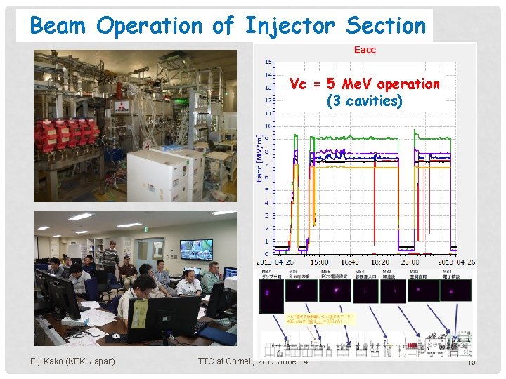
Beam Operation of Injector Section Vc = 5 Me. V operation (3 cavities) Eiji Kako (KEK, Japan) TTC at Cornell, 2013 June 14 15
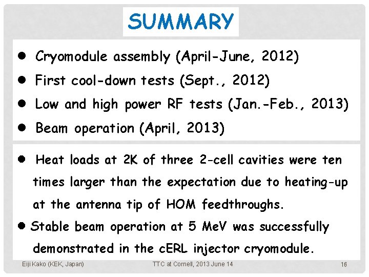
SUMMARY l Cryomodule assembly (April-June, 2012) l First cool-down tests (Sept. , 2012) l Low and high power RF tests (Jan. -Feb. , 2013) l Beam operation (April, 2013) l Heat loads at 2 K of three 2 -cell cavities were ten times larger than the expectation due to heating-up at the antenna tip of HOM feedthroughs. l Stable beam operation at 5 Me. V was successfully demonstrated in the c. ERL injector cryomodule. Eiji Kako (KEK, Japan) TTC at Cornell, 2013 June 14 16
END Thank you for your attentions. Eiji Kako (KEK, Japan) TTC at Cornell, 2013 June 14 17