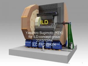
ILD Yasuhiro Sugimoto KEK for ILD concept group


- Slides: 46
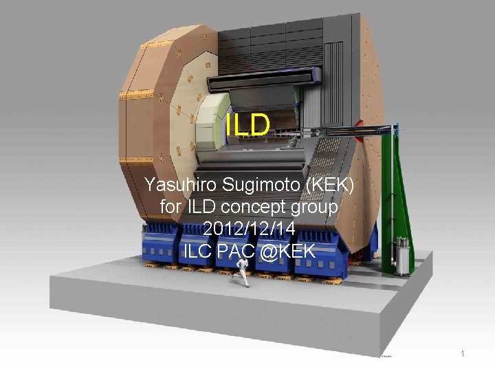
ILD Yasuhiro Sugimoto (KEK) for ILD concept group 2012/12/14 ILC PAC @KEK 1
Outline • • • Introduction Sub-systems ILD system ILD performance Cost Summary 2
Introduction 3
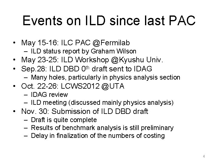
Events on ILD since last PAC • May 15 -16: ILC PAC @Fermilab – ILD status report by Graham Wilson • May 23 -25: ILD Workshop @Kyushu Univ. • Sep. 28: ILD DBD 0 th draft sent to IDAG – Many holes, particularly in physics analysis section • Oct. 22 -26: LCWS 2012 @UTA – IDAG review – ILD meeting (discussed mainly physics analysis) • Nov. 30: Submission of ILD DBD draft – Draft is quite complete – Results of benchmark analysis is still preliminary – Delay in finalization of the numbers of costing 4
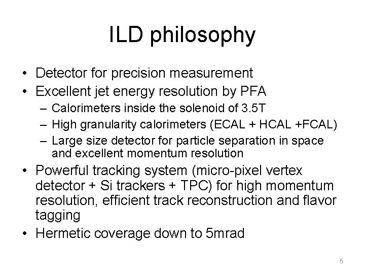
ILD philosophy • Detector for precision measurement • Excellent jet energy resolution by PFA – Calorimeters inside the solenoid of 3. 5 T – High granularity calorimeters (ECAL + HCAL +FCAL) – Large size detector for particle separation in space and excellent momentum resolution • Powerful tracking system (micro-pixel vertex detector + Si trackers + TPC) for high momentum resolution, efficient track reconstruction and flavor tagging • Hermetic coverage down to 5 mrad 5
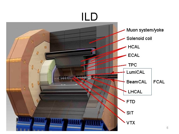
ILD Muon system/yoke Solenoid coil HCAL ECAL TPC Lumi. CAL Beam. CAL FCAL LHCAL FTD SIT VTX 6
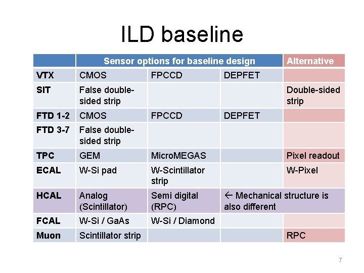
ILD baseline Sensor options for baseline design FPCCD Alternative VTX CMOS DEPFET SIT False doublesided strip FTD 1 -2 CMOS FTD 3 -7 False doublesided strip TPC GEM Micro. MEGAS Pixel readout ECAL W-Si pad W-Scintillator strip W-Pixel HCAL Analog (Scintillator) Semi digital (RPC) FCAL W-Si / Ga. As W-Si / Diamond Muon Scintillator strip Double-sided strip FPCCD DEPFET Mechanical structure is also different RPC 7
Sub-systems 8
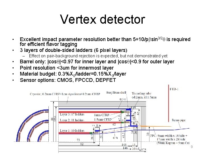
Vertex detector • • Excellent impact parameter resolution better than 5⊕ 10/pbsin 3/2 q is required for efficient flavor tagging 3 layers of double-sided ladders (6 pixel layers) – Effect on pair-background rejection is expected, but not demonstrated yet • • Barrel only: |cosq|<0. 97 for inner layer and |cosq|<0. 9 for outer layer Point resolution <3 um for innermost layer Material budget: 0. 3%X 0/ladder=0. 15%X 0/layer Sensor options: CMOS, FPCCD, DEPFET 9
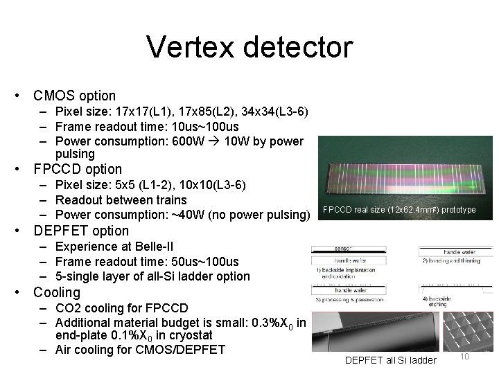
Vertex detector • CMOS option – Pixel size: 17 x 17(L 1), 17 x 85(L 2), 34 x 34(L 3 -6) – Frame readout time: 10 us~100 us – Power consumption: 600 W 10 W by power pulsing • FPCCD option – Pixel size: 5 x 5 (L 1 -2), 10 x 10(L 3 -6) – Readout between trains – Power consumption: ~40 W (no power pulsing) FPCCD real size (12 x 62. 4 mm 2) prototype • DEPFET option – Experience at Belle-II – Frame readout time: 50 us~100 us – 5 -single layer of all-Si ladder option • Cooling – CO 2 cooling for FPCCD – Additional material budget is small: 0. 3%X 0 in end-plate 0. 1%X 0 in cryostat – Air cooling for CMOS/DEPFET all Si ladder 10
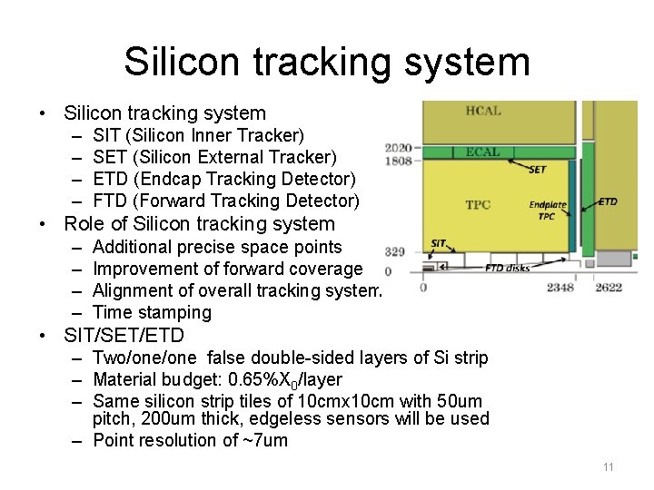
Silicon tracking system • Silicon tracking system – – SIT (Silicon Inner Tracker) SET (Silicon External Tracker) ETD (Endcap Tracking Detector) FTD (Forward Tracking Detector) • Role of Silicon tracking system – – Additional precise space points Improvement of forward coverage Alignment of overall tracking system Time stamping • SIT/SET/ETD – Two/one false double-sided layers of Si strip – Material budget: 0. 65%X 0/layer – Same silicon strip tiles of 10 cmx 10 cm with 50 um pitch, 200 um thick, edgeless sensors will be used – Point resolution of ~7 um 11
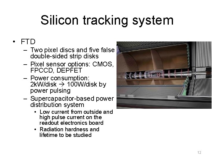
Silicon tracking system • FTD – Two pixel discs and five false double-sided strip disks – Pixel sensor options: CMOS, FPCCD, DEPFET – Power consumption: 2 k. W/disk 100 W/disk by power pulsing – Supercapacitor-based power distribution system • Low current from outside and high pulse current on the readout electronics board • Radiation hardness and lifetime to be studied 12
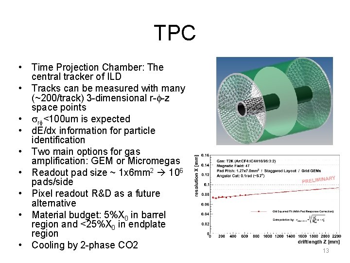
TPC • Time Projection Chamber: The central tracker of ILD • Tracks can be measured with many (~200/track) 3 -dimensional r-f-z space points • srf<100 um is expected • d. E/dx information for particle identification • Two main options for gas amplification: GEM or Micromegas • Readout pad size ~ 1 x 6 mm 2 106 pads/side • Pixel readout R&D as a future alternative • Material budget: 5%X 0 in barrel region and <25%X 0 in endplate region • Cooling by 2 -phase CO 2 13
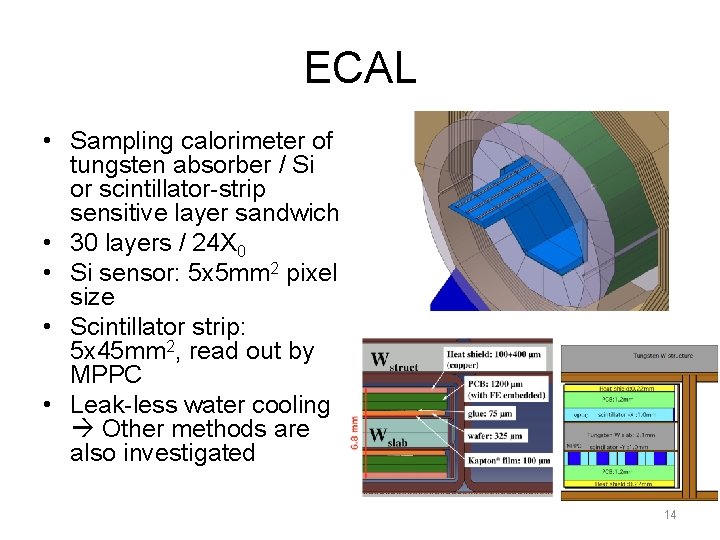
ECAL • Sampling calorimeter of tungsten absorber / Si or scintillator-strip sensitive layer sandwich • 30 layers / 24 X 0 • Si sensor: 5 x 5 mm 2 pixel size • Scintillator strip: 5 x 45 mm 2, read out by MPPC • Leak-less water cooling Other methods are also investigated 14
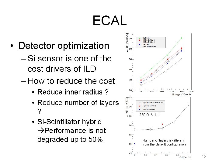
ECAL • Detector optimization – Si sensor is one of the cost drivers of ILD – How to reduce the cost • Reduce inner radius ? • Reduce number of layers ? • Si-Scintillator hybrid Performance is not degraded up to 50% 250 Ge. V jet Number of layers is different from the default configuration 15
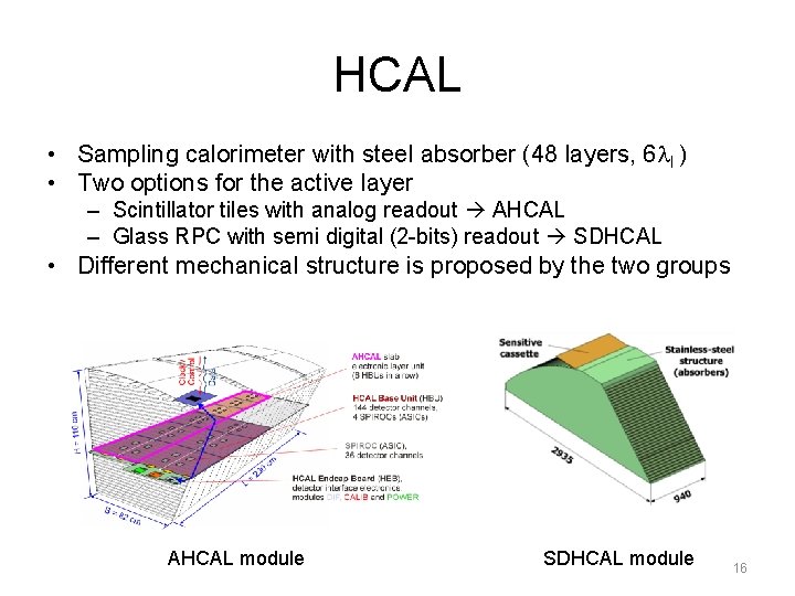
HCAL • Sampling calorimeter with steel absorber (48 layers, 6 l. I ) • Two options for the active layer – Scintillator tiles with analog readout AHCAL – Glass RPC with semi digital (2 -bits) readout SDHCAL • Different mechanical structure is proposed by the two groups AHCAL module SDHCAL module 16
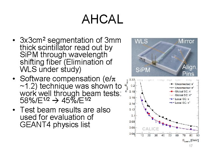
AHCAL • 3 x 3 cm 2 segmentation of 3 mm thick scintillator read out by Si. PM through wavelength shifting fiber (Elimination of WLS under study) • Software compensation (e/p ~1. 2) technique was shown to work well through beam tests: 58%/E 1/2 45%/E 1/2 • Test beam results are also used for evaluation of GEANT 4 physics list 17
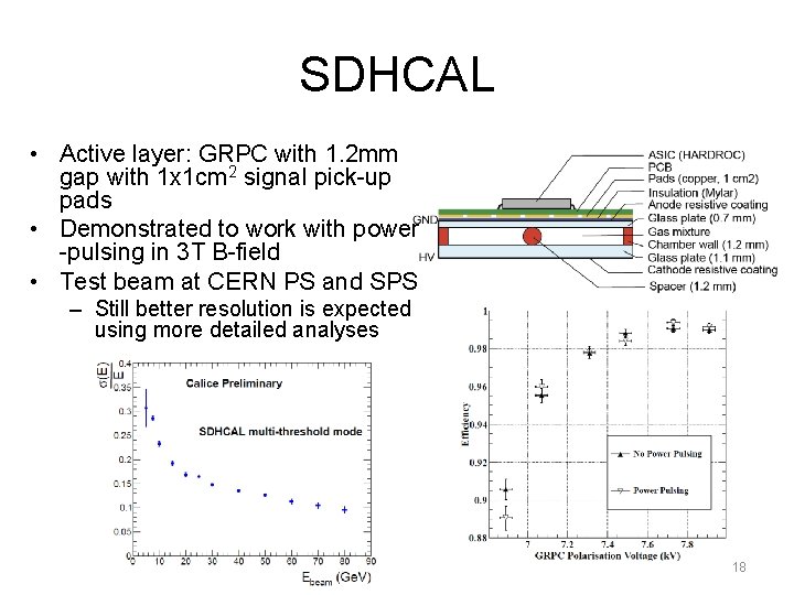
SDHCAL • Active layer: GRPC with 1. 2 mm gap with 1 x 1 cm 2 signal pick-up pads • Demonstrated to work with power -pulsing in 3 T B-field • Test beam at CERN PS and SPS – Still better resolution is expected using more detailed analyses 18
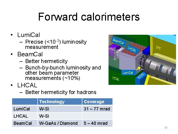
Forward calorimeters • Lumi. Cal – Precise (<10 -3) luminosity measurement • Beam. Cal – Better hermeticity – Bunch-by-bunch luminosity and other beam parameter measurements (~10%) • LHCAL – Better hermeticity for hadrons Technology Coverage Lumi. Cal W-Si 31 – 77 mrad LHCAL W-Si Beam. Cal W-Ga. As / Diamond 5 – 40 mrad 19
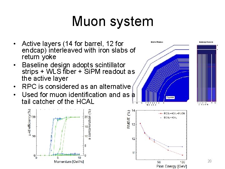
Muon system • Active layers (14 for barrel, 12 for endcap) interleaved with iron slabs of return yoke • Baseline design adopts scintillator strips + WLS fiber + Si. PM readout as the active layer • RPC is considered as an alternative • Used for muon identification and as a tail catcher of the HCAL 20
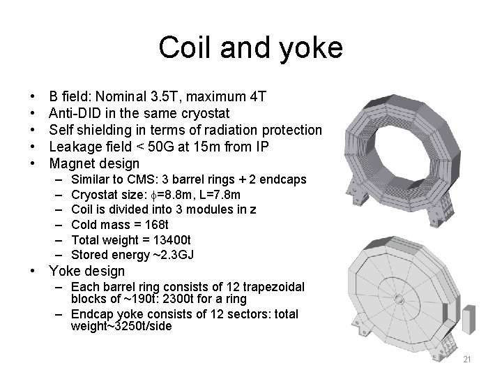
Coil and yoke • • • B field: Nominal 3. 5 T, maximum 4 T Anti-DID in the same cryostat Self shielding in terms of radiation protection Leakage field < 50 G at 15 m from IP Magnet design – – – Similar to CMS: 3 barrel rings + 2 endcaps Cryostat size: f=8. 8 m, L=7. 8 m Coil is divided into 3 modules in z Cold mass = 168 t Total weight = 13400 t Stored energy ~2. 3 GJ • Yoke design – Each barrel ring consists of 12 trapezoidal blocks of ~190 t: 2300 t for a ring – Endcap yoke consists of 12 sectors: total weight~3250 t/side 21
ILD system 22
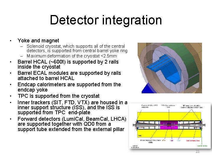
Detector integration • Yoke and magnet – Solenoid cryostat, which supports all of the central detectors, is supported from central barrel yoke ring – Maximum deformation of the cryostat <2. 5 mm • • • Barrel HCAL (~600 t) is supported by 2 rails inside the cryostat Barrel ECAL modules are supported by rails attached to barrel HCAL Endcap calorimeters are supported from the endcap yoke TPC is supported from the cryostat Inner trackers (SIT, FTD, VTX) are housed in a inner support structure (ISS), and the ISS is supported from TPC end-plate Forward detectors (Lumi. Cal, Beam. Cal, LHCA) are supported together with QD 0 from a support tube extended from the external pillar 23
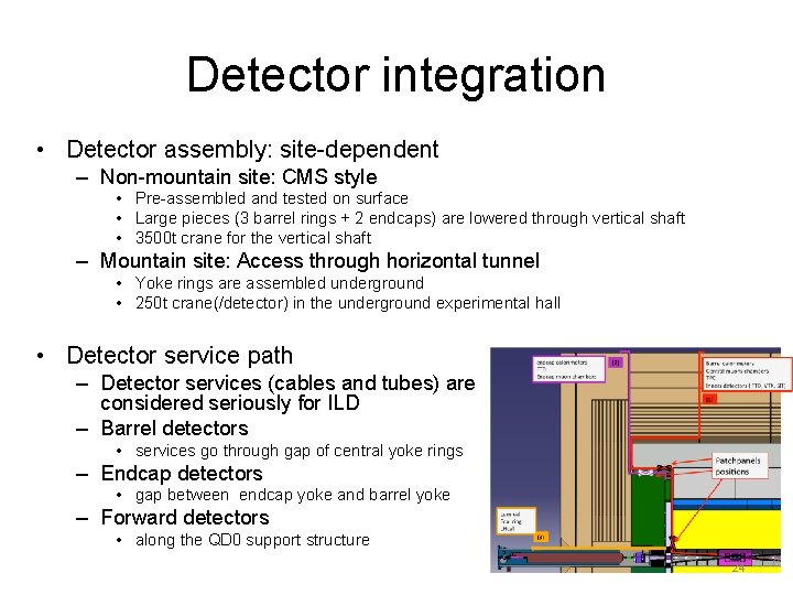
Detector integration • Detector assembly: site-dependent – Non-mountain site: CMS style • Pre-assembled and tested on surface • Large pieces (3 barrel rings + 2 endcaps) are lowered through vertical shaft • 3500 t crane for the vertical shaft – Mountain site: Access through horizontal tunnel • Yoke rings are assembled underground • 250 t crane(/detector) in the underground experimental hall • Detector service path – Detector services (cables and tubes) are considered seriously for ILD – Barrel detectors • services go through gap of central yoke rings – Endcap detectors • gap between endcap yoke and barrel yoke – Forward detectors • along the QD 0 support structure 24
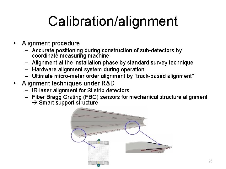
Calibration/alignment • Alignment procedure – Accurate positioning during construction of sub-detectors by coordinate measuring machine – Alignment at the installation phase by standard survey technique – Hardware alignment system during operation – Ultimate micro-meter order alignment by “track-based alignment” • Alignment techniques under R&D – IR laser alignment for Si strip detectors – Fiber Bragg Grating (FBG) sensors for mechanical structure alignment Smart support structure 25
Data acquisition • ILD DAQ: Trigger-less • Compared to LHC, ILD DAQ is less demanding in throughput, but the number of readout channels is >x 10 larger Data suppression at detector level (digitization in front-end electronics) • Most of the data volume (99%) come from beam background • Design of the DAQ system is still at the conceptual design level 26
Software tools • Core tools – LCIO • Provides a hierarchical event data • Commonly used by ILD, Si. D, CLIC – Gear: API for detector geometry – Mokka: GEANT 4 based full simulation – Marlin: Framework for further processing of the simulated data • Detector models in Mokka – Realistic model: Mechanical support structures, electronics, cables, dead materials, and cracks are also implemented – Three models created • ILD_o 1_v 05: AHCAL and Si. ECAL • ILD_o 2_v 05: SDHCAL and Si. ECAL • ILD_o 3_v 05: AHCAL and Sc. ECAL 27
Software tools • Marlin – Reconstruction and analysis system – Some new/updated packages have been developed for DBD analysis • Track reconstruction: Kaltest, IMarlin. Tr. K, Clupatra, Fwd. Tracking – replacing old Fortran code with C++ code • Particle flow: Pandora. PFA • Secondary vertex tagging: LCFIVertex, LCFIPlus – Background overlay • Pair background is not overlaid in MC study • Two-photon background events are overlaid before reconstruction 28
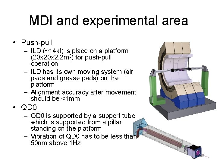
MDI and experimental area • Push-pull – ILD (~14 kt) is place on a platform (20 x 2. 2 m 3) for push-pull operation – ILD has its own moving system (air pads and grease pads) on the platform – Alignment accuracy after movement should be <1 mm • QD 0 – QD 0 is supported by a support tube which is supported from a pillar standing on the platform – Vibration of QD 0 has to be less than 50 nm above 1 Hz 29
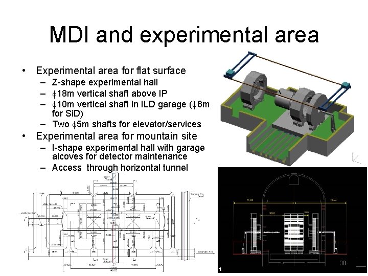
MDI and experimental area • Experimental area for flat surface – Z-shape experimental hall – f 18 m vertical shaft above IP – f 10 m vertical shaft in ILD garage (f 8 m for Si. D) – Two f 5 m shafts for elevator/services • Experimental area for mountain site – I-shape experimental hall with garage alcoves for detector maintenance – Access through horizontal tunnel 30
ILD performance 31
• ILD benchmark analysis is still on-going • All the numbers may change by the end of January 2013 32
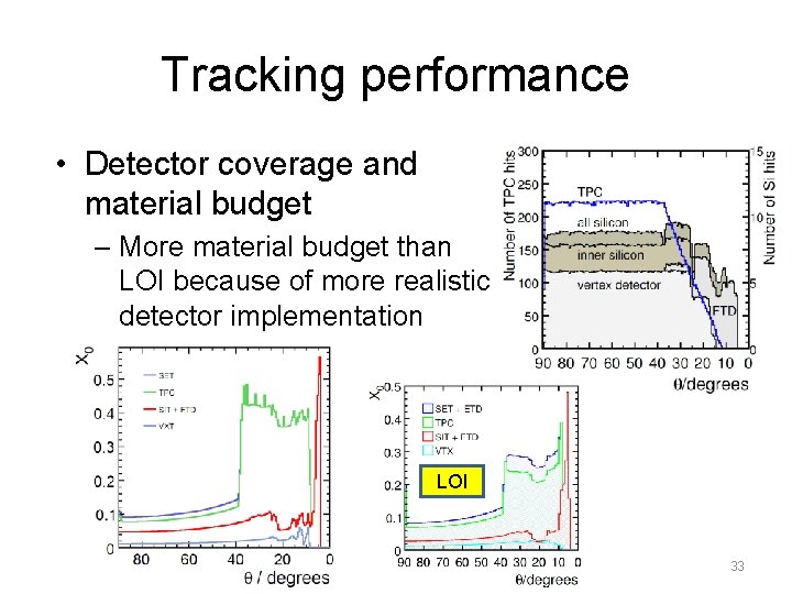
Tracking performance • Detector coverage and material budget – More material budget than LOI because of more realistic detector implementation LOI 33
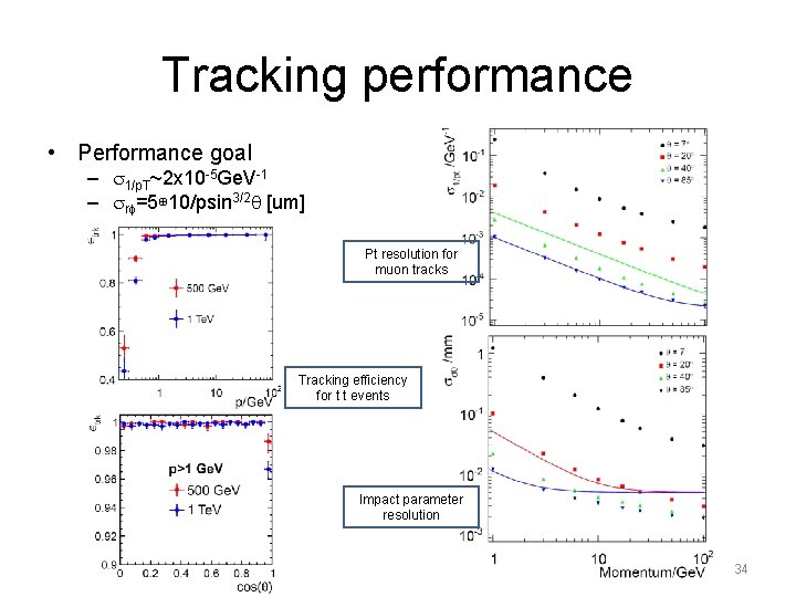
Tracking performance • Performance goal – s 1/p. T~2 x 10 -5 Ge. V-1 – srf=5⊕ 10/psin 3/2 q [um] Pt resolution for muon tracks Tracking efficiency for t t events Impact parameter resolution 34
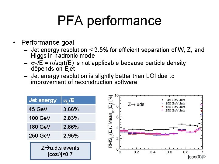
PFA performance • Performance goal – Jet energy resolution < 3. 5% for efficient separation of W, Z, and Higgs in hadronic mode – s. E/E = a/sqrt(E) is not applicable because particle density depends on Ejet – Jet energy resolution is slightly better than LOI due to improvement of reconstruction software Jet energy s. E/E 45 Ge. V 3. 66% 100 Ge. V 2. 83% 180 Ge. V 2. 86% 250 Ge. V 2. 95% Z u, d, s events |cosq|<0. 7 35
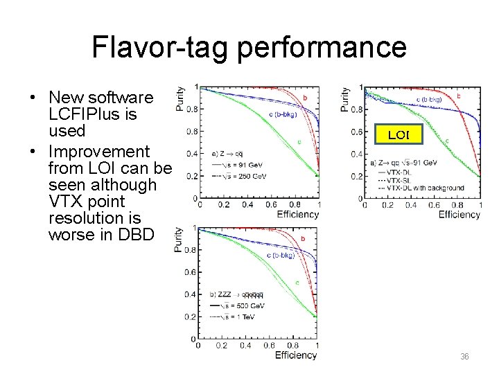
Flavor-tag performance • New software LCFIPlus is used • Improvement from LOI can be seen although VTX point resolution is worse in DBD LOI 36
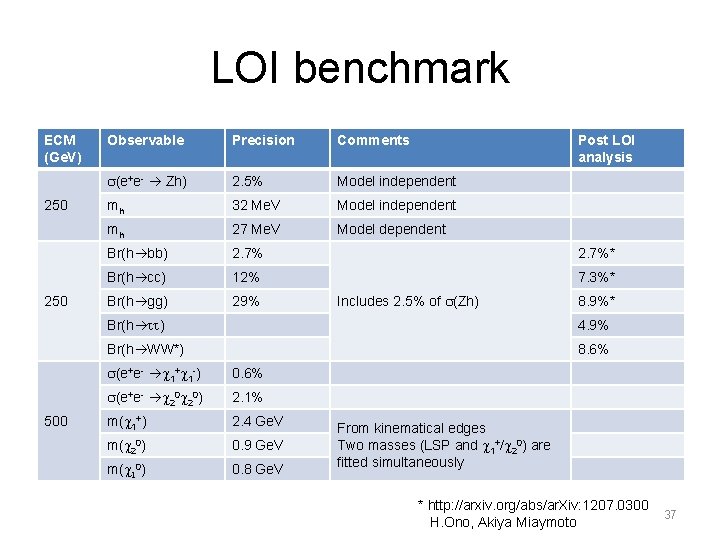
LOI benchmark ECM (Ge. V) 250 500 Observable Precision Comments Post LOI analysis s(e+e- Zh) 2. 5% Model independent mh 32 Me. V Model independent mh 27 Me. V Model dependent Br(h bb) 2. 7%* Br(h cc) 12% 7. 3%* Br(h gg) 29% Includes 2. 5% of s(Zh) 8. 9%* Br(h tt) 4. 9% Br(h WW*) 8. 6% s(e+e- c 1+c 1 -) 0. 6% s(e+e- c 20) 2. 1% m(c 1+) 2. 4 Ge. V m(c 20) 0. 9 Ge. V m(c 10) 0. 8 Ge. V From kinematical edges Two masses (LSP and c 1+/c 20) are fitted simultaneously * http: //arxiv. org/abs/ar. Xiv: 1207. 0300 H. Ono, Akiya Miaymoto 37
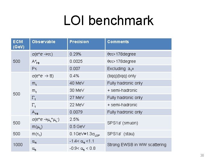
LOI benchmark ECM (Ge. V) 500 500 1000 Observable Precision Comments s(e+e- tt) 0. 29% qtt>178 degree At. FB 0. 0025 qtt>178 degree Pt 0. 007 Excluding a 1 n s(e+e- tt) 0. 4% (bqq) only mt 40 Me. V Fully hadronic only mt 30 Me. V + semi-hadronic Gt 27 Me. V Fully hadronic only Gt 22 Me. V + semi-hadronic AFB 0. 0079 Fully hadronic only s(e+e- m. L+m. L-) 2. 5% m(m. L) 0. 5 Ge. V m(t 1) 0. 1 Ge. V⊕ 1. 3 s. LSP a 4 -1. 4< a 4 <1. 1 a 5 -0. 9< a 5 < 0. 8 SPS 1 a’ (smuon) SPS 1 a’ (stau) Strong EWSB in WW scattering 38
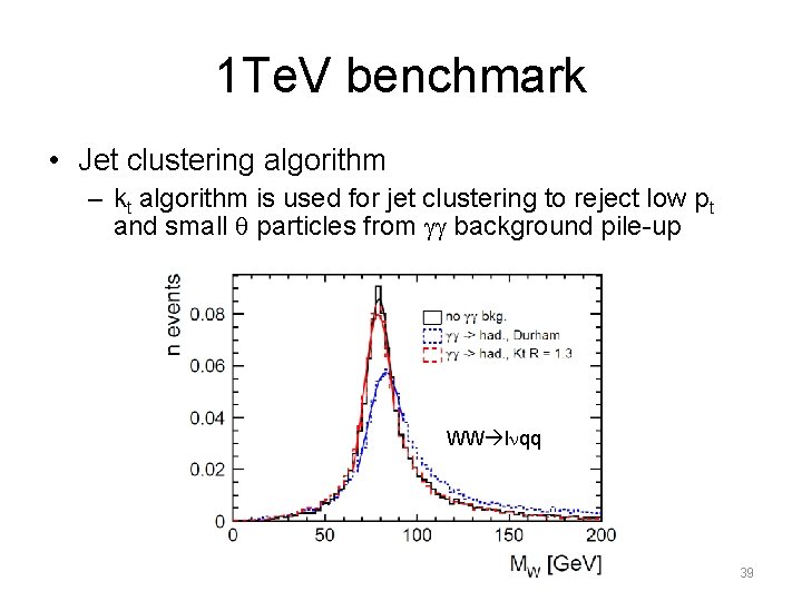
1 Te. V benchmark • Jet clustering algorithm – kt algorithm is used for jet clustering to reject low pt and small q particles from gg background pile-up WW lnqq 39
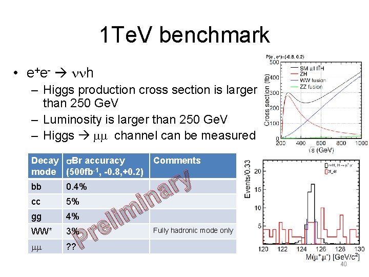
1 Te. V benchmark • e+e- nnh – Higgs production cross section is larger than 250 Ge. V – Luminosity is larger than 250 Ge. V – Higgs mm channel can be measured Decay s. Br accuracy mode (500 fb-1, -0. 8, +0. 2) Comments y r a n i m i l e r P bb 0. 4% cc 5% gg 4% WW* 3% mm ? ? Fully hadronic mode only 40
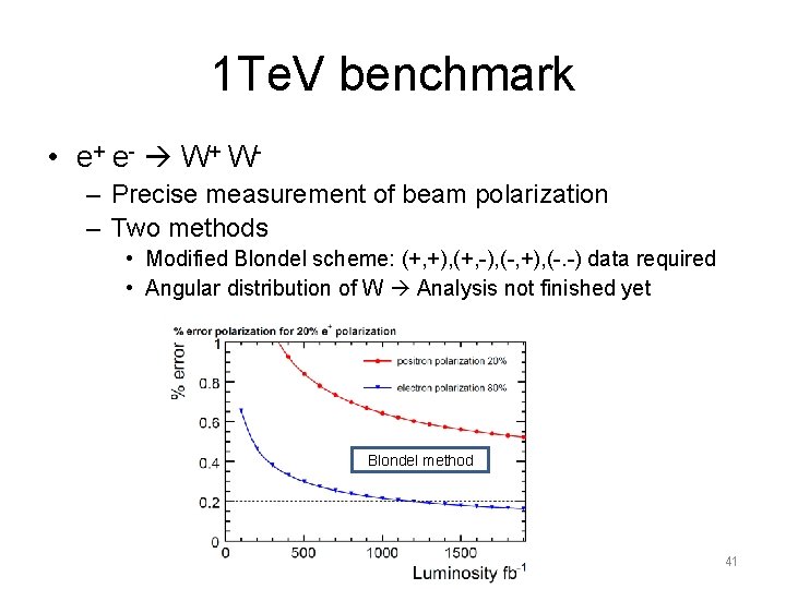
1 Te. V benchmark • e+ e - W + W – Precise measurement of beam polarization – Two methods • Modified Blondel scheme: (+, +), (+, -), (-, +), (-. -) data required • Angular distribution of W Analysis not finished yet Blondel method 41
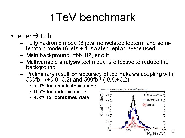
1 Te. V benchmark • e+ e - t t h – Fully hadronic mode (8 jets, no isolated lepton) and semileptonic mode (6 jets + 1 isolated lepton) were used – Main background: ttbb, tt. Z, and tt – Multivariable analysis technique is effective to reduce the background – Preliminary result on accuracy of top Yukawa coupling with 500 fb-1 (+0. 8, -0. 2) and 500 fb-1 (-0. 8, +0. 2) • 7. 0% for semi-leptonic mode • 6. 5% for hadronic mode • 4. 8% for combined data 42
LOI-DBD common benchmark • We used e+e- t t channel for the comparison between LOI and DBD analysis @500 Ge. V • Forward-backward asymmetry is determined by hadronic decay mode • Vertex charge determination is needed good benchmark for vertex detector/finding • Results with 500 fb-1, P(e-, e+)=(-0. 8, +0. 3) : – At. FB = Coming soon (DBD) – At. FB = 0. 334± 0. 0079 (LOI) 43
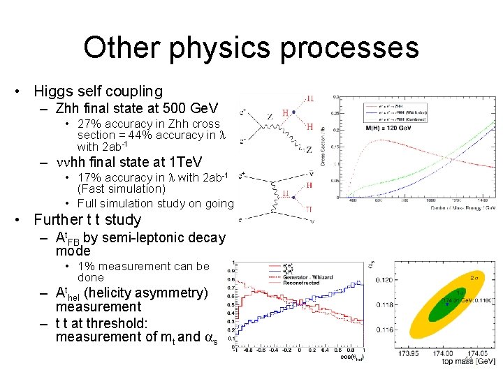
Other physics processes • Higgs self coupling – Zhh final state at 500 Ge. V • 27% accuracy in Zhh cross section = 44% accuracy in l with 2 ab-1 – nnhh final state at 1 Te. V • 17% accuracy in l with 2 ab-1 (Fast simulation) • Full simulation study on going • Further t t study – At. FB by semi-leptonic decay mode • 1% measurement can be done – Athel (helicity asymmetry) measurement – t t at threshold: measurement of mt and as 44
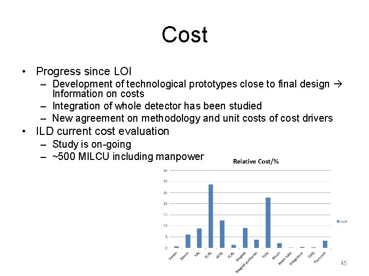
Cost • Progress since LOI – Development of technological prototypes close to final design Information on costs – Integration of whole detector has been studied – New agreement on methodology and unit costs of cost drivers • ILD current cost evaluation – Study is on-going – ~500 MILCU including manpower 45
Summary • Detailed baseline design of ILD based on validated detector technologies has been presented • Compared with LOI, more realistic design including support structure, cables, other services, and dead material has been made • Although the material budget has been increased, better detector performance than LOI has been obtained thanks to the improvement of software tools and analysis methods • New benchmark processes at 1 Te. V have been studied with 2 -photon process background overlaid (We still need few weeks to finalize the results, though) • We still need detector R&D, particularly in the engineering aspect, after completion of DBD 46