KEK status report S TanakaKEK 13 th DEPFET
 13 th DEPFET workshop 2013/06")
 • Sub-parts @KEK Be pipes (2 sets) IP")
")

 After Be pipe production, gas leak has tested, but. . .")
 (Done) 2012.")
 • Beam pipe should be produced before 2015 July.")


 in this year")

 • 1, VXD design : remaining PXD PP area (also")
 PP placement Table(height,")

")


 Or can")


 Possible space for sensor, but also important to shield BG.")
, ->")

 Reminder to me as liaison 2013. 6")

: when cabling work will start other than VXD")
 Transfer")


")


- Slides: 44
KEK status report S. Tanaka(KEK) 13 th DEPFET workshop 2013/06
Beam pipe Status Current status(2013 June) • Sub-parts @KEK Be pipes (2 sets) IP chamber Outer pipe for BEASTII Tantalum block for second production 1, IP chamber connection study on Ti-Ti EBW: OK 2, Thermal effect study of gold plated Tantalum by EBW: OK 3, Drilling test for Ti-Ta material with HIP process (inner tube): OK 4、Tools for IP chamber and crotch part connection by EBW : OK Ongoing(or in preparation) 5, IP chamber inner tube production (Be-Ti connection) (Problem!!) 6, Silver or copper plating (1 um) inside of crotch part for reducing thermal effect. 7, Gold plating(10 um) for inner IP chamber. 8, drilling of crotch part inner shape (Ta) 9, EBW test for IP chamber connection(Ti-Ti) and IP with crotch part(Ta-Ti)
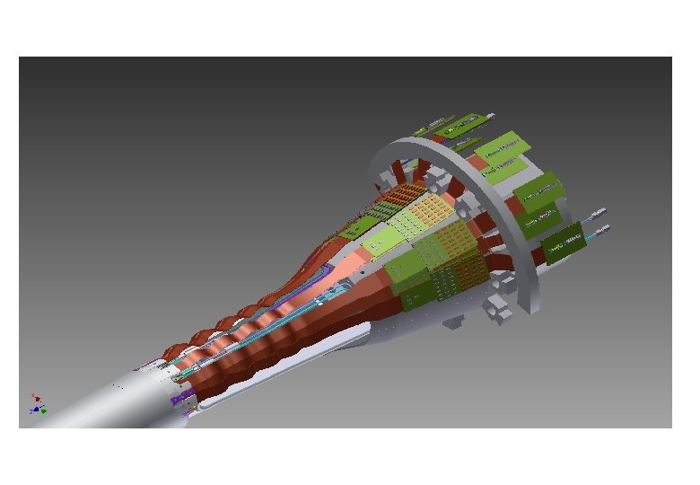
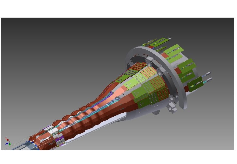
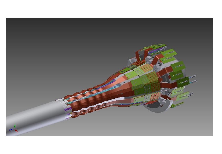
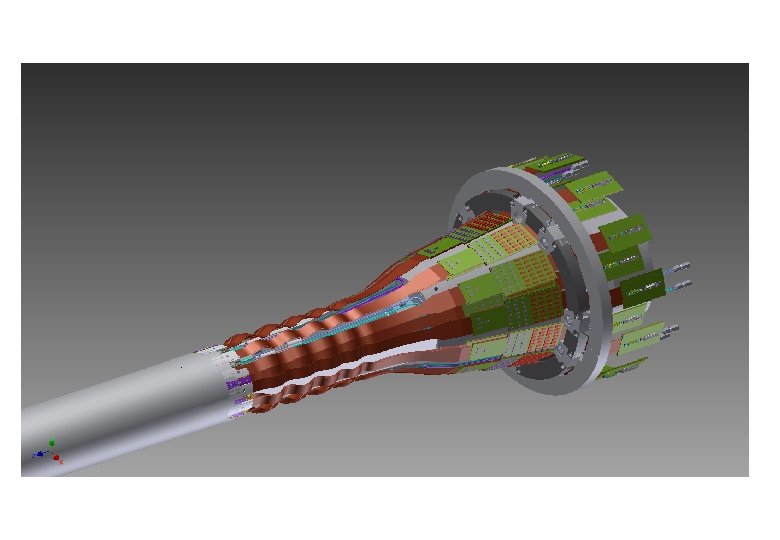
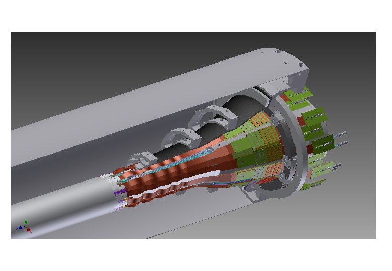
Beam pipe design PXD structure is fit to this design (confirmed by mockup test)
Au plating test for Ti tube The thickness is controlled by time.
Inner tube production(Problem) After Be pipe production, gas leak has tested, but. . . • After brazing process (Be-Ti), leak has found • (less than 5*10 -8 Pa・m 3/sec) • Now we are investigating the situation. I personally expect that this problem gives around 2~4 month delay. Today's news: Company applied leak test again. The leak was found only the area between Be-Ti!? . . . we should be careful for the situation
Beam Pipe production Start End Cupper plating test (for IP inner tube) (Done) 2012. 9 2012. 12 Tantalum and titanium part connection and cutting test (Done) 2012. 12 Crotch part machining (forward) 2013. 4 2013. 7 Crotch part machining (backward) 2013. 4 2013. 7 2012. 12 2013. 3 IP inner chamber production 2013. 1 2013. 3 Gold plating of inner tube 2013. 4 connection of IP chamber inner and outer tube (EBW for Ti-Ti) 2013. 5 2013. 8 Thermal stress test with EBW and brazing 2012. 11 2013. 3 Crotch part connection (EBW or brazing) 2013. 8 2013. 10 2013. 12 Tooling production for connection of IP chamber and crotch part 2012. 11 12 2013. 1 2 3 4 5 6 Yellow: test, Blue: IPchamber, Green : Crotch part 7 8 9 10 11 12
2 nd beam pipe(for physics) • Beam pipe should be produced before 2015 July. • In 2014 fiscal year, 2 nd beam pipe will be produced. • BEAST pipe, production has took more than one year, but – IP chamber (outer and inner pipe will produced in parallel – Crotch part will produced in parallel with IP chamber – All of production jigs are prepared in this production
Crotch part Done • • Prodution is ongoing Starting from this June(scheduled from April, but delay by tendering work) Done
Tool for Ti-Ti and Ta-Ta EBW The precision of this procedure may affect on PXD mount EBW test is ongoing with Ti dummy pipes for Ti-Ti test
Job list on KEK in this year KEK work list(design work+production) in this year 1, End-flange (3 D->2 D production design->production) 2, Heavy metal(3 D->2 D production design->production) (After finalizing VXD design by Tscharlie, Koike-san will start) 3, SVD assembly table and related jigs design 4, SVD alignment tool 5, connection bar to join FW and BW on assembling work. 6, Endring gluing jigs? 7, BP+PXD assembly table and related jigs design (Those subjects are main topics in KEK) 8, End-ring (final production) 9, VXD system transport jig design(also we should have something before SVD system assembly because of heavy structure) 10, VXD installation jig design. 11, BEAST VXD design
VXD assembly
VXD mechanics meeting (May) • 1, VXD design : remaining PXD PP area (also confirmation by SVD) BP+PXD assembly table design -> we can start now! Koike-san will start design-> introducing VXD community • 2, SVD ladder mount requirements Table(height, free space for service) Rotation of SVD system Coordinate measurement tool (precision) (Origin is top of layer 6 th endring) ladder hanging tool (box->endring): (KEK) Toru summarize requirements from SVD community
3, PXD system mount requirement PXD system grubbing tool (by MPI) PP placement Table(height, free space for service) Tanaka+Koike and Tscharlie will take care. 4, RVC system transport to KEK (Kanazawa-san) Installation discussion will be finalized in this Nov. 5, SVD sub-parts production (Tsuboyama-san) Endring , Origami, SVD ladder mount table 6, Tanaka have to take care(management, not design) PXD kapton flex, Beam pipe, Heavy metal, BP+PXD table, CFRP production, End flange, Alignment tool, 7, We will have VXD monthly meeting(Tanaka) 8, Keep discussion about possibility of VXD sensors on BEAST phase. -Ro. I test -Injection and noise test 9, PXD hut in B 1 area? (Requested by Christian)
BP+PXD assembly table • We have been discussing about space allocation for detector and services. • We start discussing system assembly procedure and sharing preparation work. – BP+shield: heavy structure – PXD: need fine positioning onto beam pipe Gemba discussion in VXD meeting Karsten's comments help to imagine a assembly scenario
2003/3/14(SVD 2 case as reference)
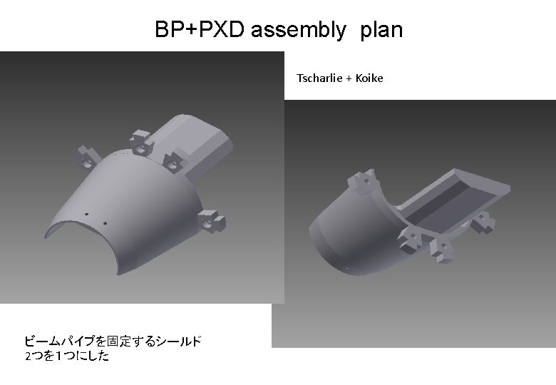
Connection area with support structure Heavy metal pieces should make in one structure for each halves
BP support jig VXD組立順
Connecting lower heavy metal shield
Put beam pipe onto heavy metal
Adopt upper heavy metal shield
Does bending shape fit to space between SVD and PXD? (Ushiroda-san's question) Or can it reduce the hight ? This area is also critical for BG shielding by heavy metal ( for Touschek)
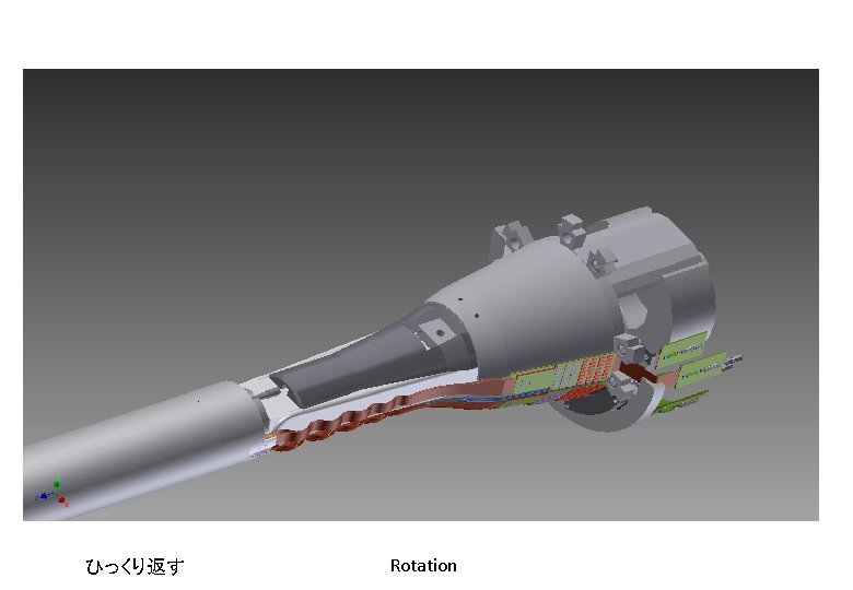
Bellows pipe should be connected after VXD assembly KEK group discussing about how to connect this pipe.
Clearance between SVD and PXD by mockup test No screw in SVD ladder design (Be careful)
CFRP cover CFRP Sandwich • KEK group want to make VXD CFRP cover with more simple structure. – 1 mmt CFRP + Airex + heater • Reason: – more clear estimation of mechanical strength – (On above case, it is not easy to estimate gluing effect) – Cost (almost half: dominated by molding process)
BG monitor position (option) Possible space for sensor, but also important to shield BG. (As small as possible: PIN diode? ) • Monitoring BG is quite important to decide ramp-up detector and send beam abort signal to machine
Middle term schedule on KEK IR mechanics • 2013 May: VXD design (finial), -> – Assembly table and tools design should start, – Production design (final) of VXD subparts and assembly tools should be started • "2013 June Final BACKWARD SVD design(+Outer cover? )" • 2013 Sep. : Almost of all production design of subparts should be finalized (start ordering work). – Starting design of VXD installation sub-parts. – Starting jig design for BEAST sensors • 2014 Jan. : Almost of all VXD mechanics parts are prepared – (2014 Feb~: SVD structure assembly + alignment study) – BEAST beam pipe production will be finished • 2014 Summer: Almost of all VXD subparts are prepared – BP+PXD assembly table and tools (done), – SVD ladder mount table and tools (done), – SVD structure should be prepared (final), – SVD structure should sit on SVD ladder mount table – Installation tool production should be started • 2015 July VXD system integration
backup
Subjects between PXD-KEK (for PXD commissioning) Reminder to me as liaison 2013. 6
• VXD service space and dry volume – Need bracket requests and how to achieve "warm dry volume" • Kapton flex: assisting flex production (Tanaka) Passive components (Capacitors): mount work on Kapton flex by Taiyo + electronic test(Tanaka should help on production) Mounting Rings on beam pipe: After BP production, KEK will be produced(Tscharlie+Tanaka) alignment/environmental sensors (fibers) : need path and dimension information Assembly tools: BP+PXD assembly table: PXD mount arm and support system will be produced by MPI, KEK will be make screw connection with this system on the table. (Tanaka+Tscharlie)
• Power Cables (all types): when cabling work will start other than VXD area? Data Cables : when cabling work will start? Connectors: need to send Taiyo before Kapton flex production Cable confectioning and testing: need mockup test @KEK? Patch panels: (service work procedure defined by Tscharlie+Tanaka) Docks: need Screw holes request to Kohriki-san. Connection between Docks and screws on CDC is taken by Tscharlie. Power Supplies: rack space allocation is taken care by Ushiroda-san DHH & controller : rack space allocation is taken care by Ushiroda-san ATCA & ONSEN: rack space allocation is taken care by Itoh-san (Power line is by Uehara-san) • Software – Tracking: T. Hara-san(KEK side) – BG estimation: Nakayama-san
• Cooling IBBelle: Power line+ CO 2 inlet/exhaust piping (Tanaka will help) Transfer lines & components: need schedule and space request Dry air plant: KEK group will help. Operation (KEK cryogenics group) Installation Procedure: VXD group + KEK group Design(MPI, DESY->KEK) Mock up: (MPI-KEK) BEAST sensors: need bracket design for sensors. Beam abort signal: who will take care? Requests from PXD(mainly Christian and Hans-Gunther): Clean booth for PXD system test in Tsukuba B 1 Humidity control in Tsukuba B 1 CO 2 cooling system (by open system) in Tsukuba B 1 (who is PXD commissioning leader at KEK? ) Other issue: How to buy a car for PXD group?
Discussion about VXD installation • Summary of the discussion on the installation scenario • 1. Alternative scenario • The RVC is basically established. The major concern is a disassemble procedure when the lock nut is stuck after held long time (in the forward). In case such a condition happens, the VXD will be pulled out using similar mechanism as the baseline scenario. • The RVC should be applied for both ends. • How about the cabling in the forward space? • The basic philosophy should be kept in Super. KEKB that for a trouble of the accelerator, the detector should not be touched. When a trouble happens on a forward bellows pipe, it should be replaced in situ • The detailed design and mock-up test including service work will be finished by November 2013. Also mechanical analysis on each step of installation will be provided. • DESY and MIP can provide people for the installation and un-installation of the VXD according to this scenario. .
Discussion about VXD installation • 2. Baseline scenario • To detect that the VXD is stuck during sliding, a protection mechanism using a load-lock will be provided between the VXD and the QCS cryostat. • The RVC seems useful for the backward connection. The compatibility with the on-going design of the QCS will be checked by KEK. • Since the IP chamber is fragile, the replacement of the forward bellows pipe should be done in a good working condition by pulling out the VXD. Judging from the experience of KEKB, to replace the bellows by sliding into the forward hollow of the CDC is quite risky. • 3. For both • It is necessary to take into account that a shield enclosing the bellows is requested. The spec of the shield will be provided by KEK (minimum thickness, etc. ) • At the start of Phase 2, the installation scenario must be tested.
Another topics (QCS)
QCS cryostat shape has modified Before
After In order to stabilize beam pipe and magnets inside of QCS
Jigs Design work Preparing 2 D production drawings of each sub-parts for VXD system and assembly jigs