
CCD based Vertex Detector for GLC Yasuhiro Sugimoto
CCD based Vertex Detector for GLC Yasuhiro Sugimoto KEK/Niigata/Tohoku/Toyama Collaboration @VERTEX 2003, Sep. 16, 2003 CCD based Vertex Detector for GLC 1
Outline l Project Overview of GLC l l l CCD Vertex Detector l l Accelerator Detector Merit/Demerit of CCD at GLC/TESLA R&D Status l Radiation Damage : Energy Dependence of Electron Damage l l l Dark Current, Flat-band Voltage Shift, Hot Pixels Charge Transfer Inefficiency Summary CCD based Vertex Detector for GLC 2
GLC Project l JLC has changed its name as GLC (Global Linear Collider) l l l 500 Ge. V – 1 Te. V LC based on X-band linac Future global organization is anticipated Start experiment at 2013 CCD based Vertex Detector for GLC 3
GLC Accelerator CCD based Vertex Detector for GLC 4

GLC Acc. Parameters 500 Ge. V 1000 Ge. V Luminosity 2. 5 x 1034 cm-2 s-1 Rep. rate 150 Hz 100 Hz Bunch population 0. 75 x 1010 # of bunch/train 192 Bunch separation 1. 4 ns sx/sy at IP 243/3 nm 219/2. 1 nm sz at IP 110 mm CCD based Vertex Detector for GLC 5
GLC Beam Structure GLC/NLC: Readout between trains ( 1 frame/6. 7 ms ) TESLA: Readout during trains ( 1 frame/50 ms ) GLC/NLC is more favorable for vertex detectors CCD based Vertex Detector for GLC 6
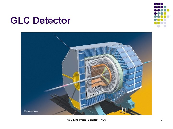
GLC Detector CCD based Vertex Detector for GLC 7
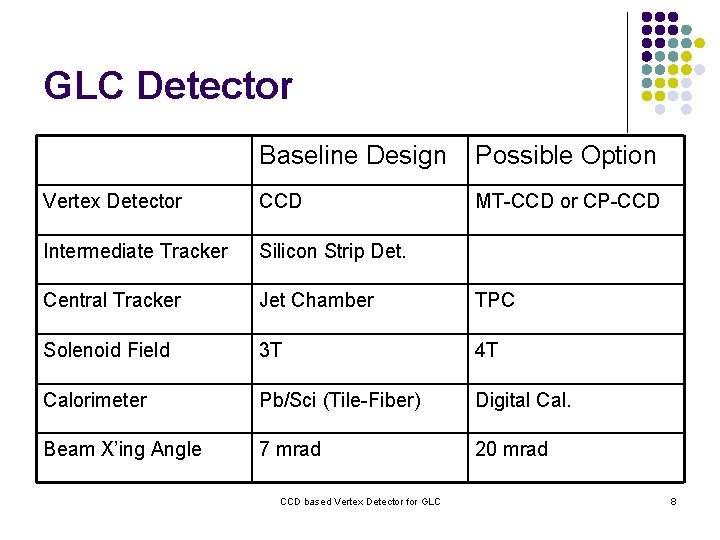
GLC Detector Baseline Design Possible Option Vertex Detector CCD MT-CCD or CP-CCD Intermediate Tracker Silicon Strip Det. Central Tracker Jet Chamber TPC Solenoid Field 3 T 4 T Calorimeter Pb/Sci (Tile-Fiber) Digital Cal. Beam X’ing Angle 7 mrad 20 mrad CCD based Vertex Detector for GLC 8
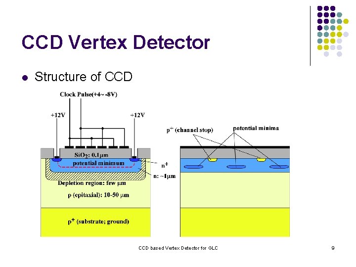
CCD Vertex Detector l Structure of CCD based Vertex Detector for GLC 9
CCD Vertex Detector l Structure of CCD (Cont. ) CCD based Vertex Detector for GLC 10
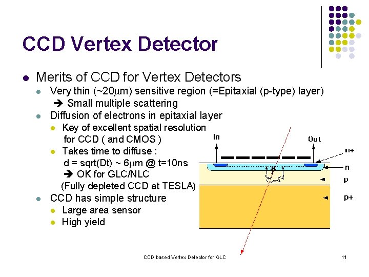
CCD Vertex Detector l Merits of CCD for Vertex Detectors l l Very thin (~20 mm) sensitive region (=Epitaxial (p-type) layer) Small multiple scattering Diffusion of electrons in epitaxial layer l l l Key of excellent spatial resolution for CCD ( and CMOS ) Takes time to diffuse : d = sqrt(Dt) ~ 6 mm @ t=10 ns OK for GLC/NLC (Fully depleted CCD at TESLA) CCD has simple structure l l Large area sensor High yield CCD based Vertex Detector for GLC 11
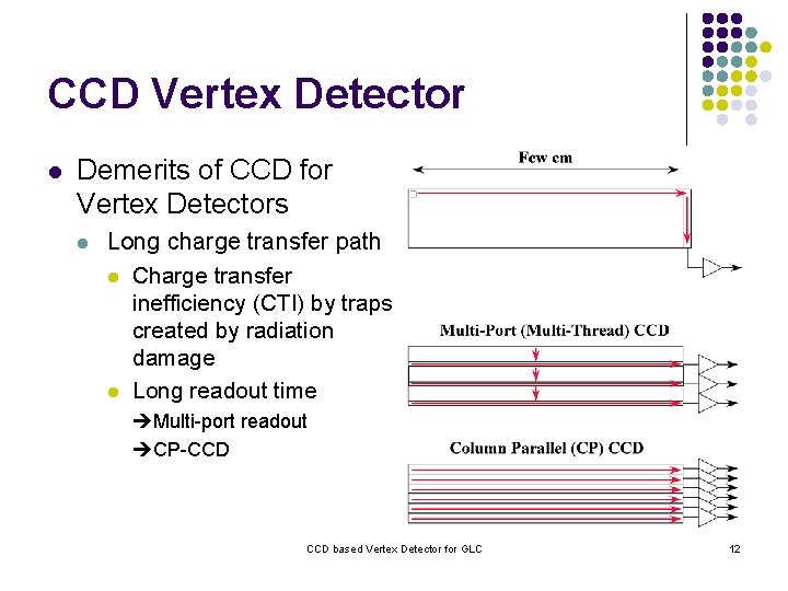
CCD Vertex Detector l Demerits of CCD for Vertex Detectors l Long charge transfer path l Charge transfer inefficiency (CTI) by traps created by radiation damage l Long readout time Multi-port readout CP-CCD based Vertex Detector for GLC 12
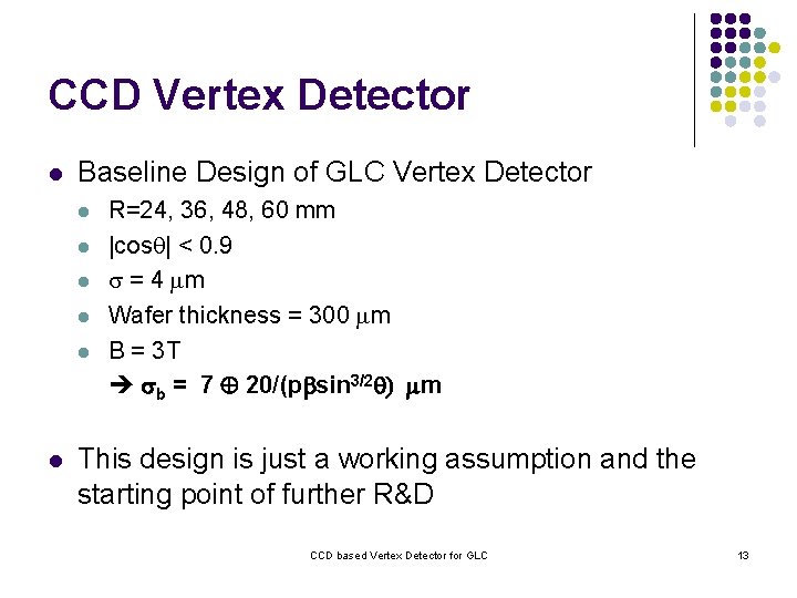
CCD Vertex Detector l Baseline Design of GLC Vertex Detector l l l R=24, 36, 48, 60 mm |cosq| < 0. 9 s = 4 mm Wafer thickness = 300 mm B = 3 T sb = 7 20/(pbsin 3/2 q) mm This design is just a working assumption and the starting point of further R&D CCD based Vertex Detector for GLC 13
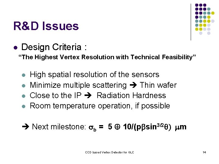
R&D Issues l Design Criteria : “The Highest Vertex Resolution with Technical Feasibility” l l High spatial resolution of the sensors Minimize multiple scattering Thin wafer Close to the IP Radiation Hardness Room temperature operation, if possible Next milestone: sb = 5 10/(pbsin 3/2 q) mm CCD based Vertex Detector for GLC 14
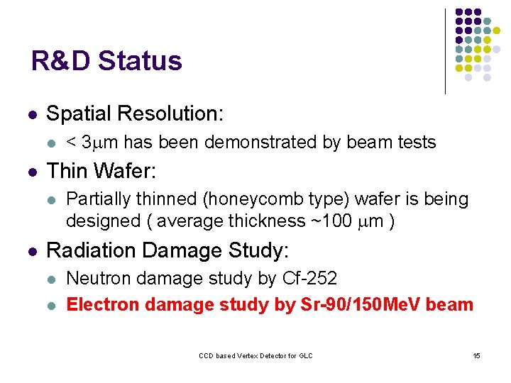
R&D Status l Spatial Resolution: l l Thin Wafer: l l < 3 mm has been demonstrated by beam tests Partially thinned (honeycomb type) wafer is being designed ( average thickness ~100 mm ) Radiation Damage Study: l l Neutron damage study by Cf-252 Electron damage study by Sr-90/150 Me. V beam CCD based Vertex Detector for GLC 15
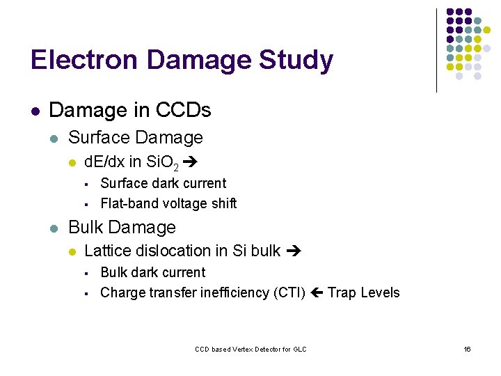
Electron Damage Study l Damage in CCDs l Surface Damage l d. E/dx in Si. O 2 § § l Surface dark current Flat-band voltage shift Bulk Damage l Lattice dislocation in Si bulk § § Bulk dark current Charge transfer inefficiency (CTI) Trap Levels CCD based Vertex Detector for GLC 16
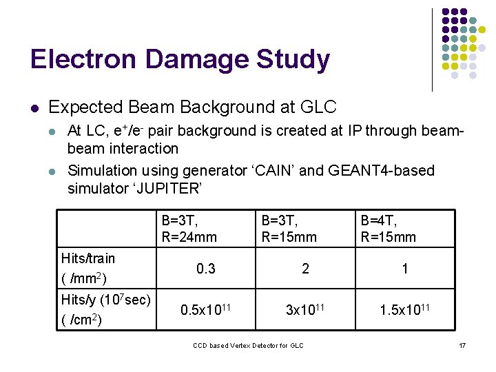
Electron Damage Study l Expected Beam Background at GLC l l At LC, e+/e- pair background is created at IP through beam interaction Simulation using generator ‘CAIN’ and GEANT 4 -based simulator ‘JUPITER’ B=3 T, R=24 mm Hits/train ( /mm 2) Hits/y (107 sec) ( /cm 2) B=3 T, R=15 mm B=4 T, R=15 mm 0. 3 2 1 0. 5 x 10¹¹ 3 x 10¹¹ 1. 5 x 10¹¹ CCD based Vertex Detector for GLC 17
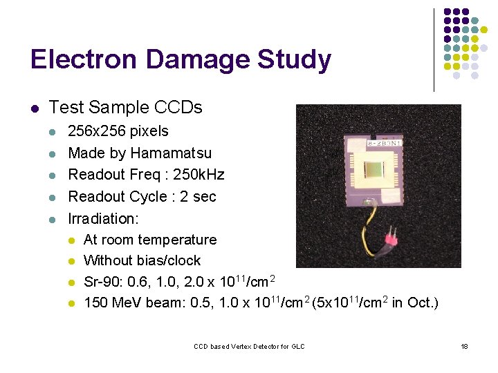
Electron Damage Study l Test Sample CCDs l l l 256 x 256 pixels Made by Hamamatsu Readout Freq : 250 k. Hz Readout Cycle : 2 sec Irradiation: l At room temperature l Without bias/clock l Sr-90: 0. 6, 1. 0, 2. 0 x 1011/cm 2 l 150 Me. V beam: 0. 5, 1. 0 x 1011/cm 2 (5 x 10¹¹/cm 2 in Oct. ) CCD based Vertex Detector for GLC 18
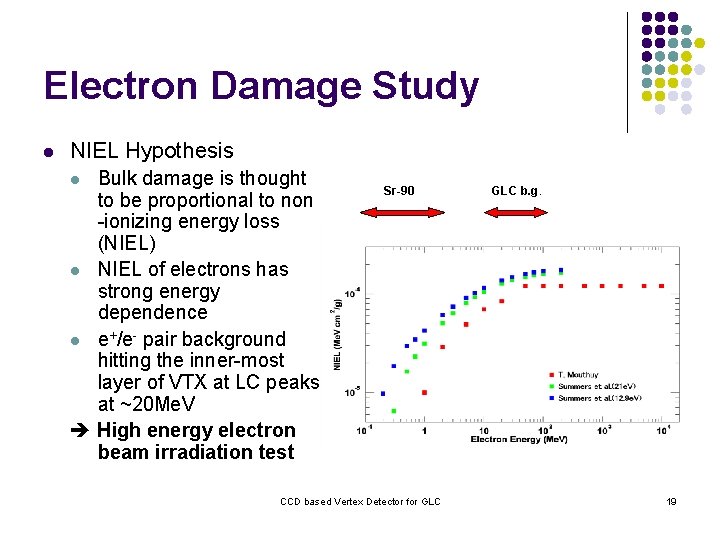
Electron Damage Study l NIEL Hypothesis Bulk damage is thought to be proportional to non -ionizing energy loss (NIEL) l NIEL of electrons has strong energy dependence l e+/e- pair background hitting the inner-most layer of VTX at LC peaks at ~20 Me. V High energy electron beam irradiation test l Sr-90 CCD based Vertex Detector for GLC b. g. 19
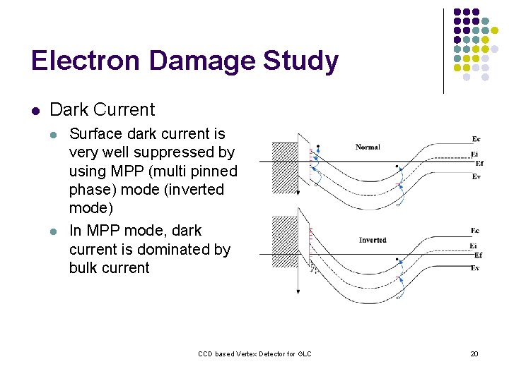
Electron Damage Study l Dark Current l l Surface dark current is very well suppressed by using MPP (multi pinned phase) mode (inverted mode) In MPP mode, dark current is dominated by bulk current CCD based Vertex Detector for GLC 20
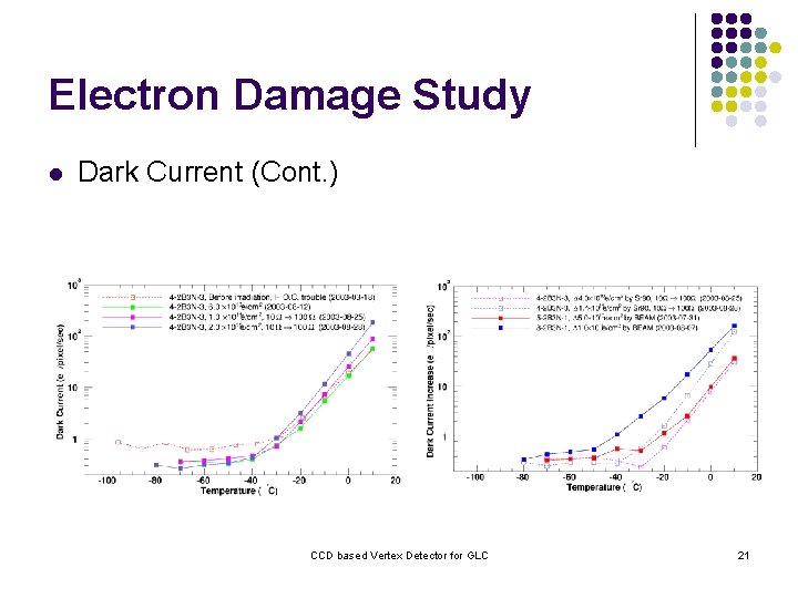
Electron Damage Study l Dark Current (Cont. ) CCD based Vertex Detector for GLC 21

Electron Damage Study l Flat-band Voltage Shift l l l Surface damage in Si. O 2 (positive charge build-up) causes shift of operation voltage FVS is observed as shift of MPP threshold No significant FVS is observed up to 2 x 10¹¹ e/cm 2 irradiation Amplitude of Negative Clock Voltage (V) CCD based Vertex Detector for GLC 22
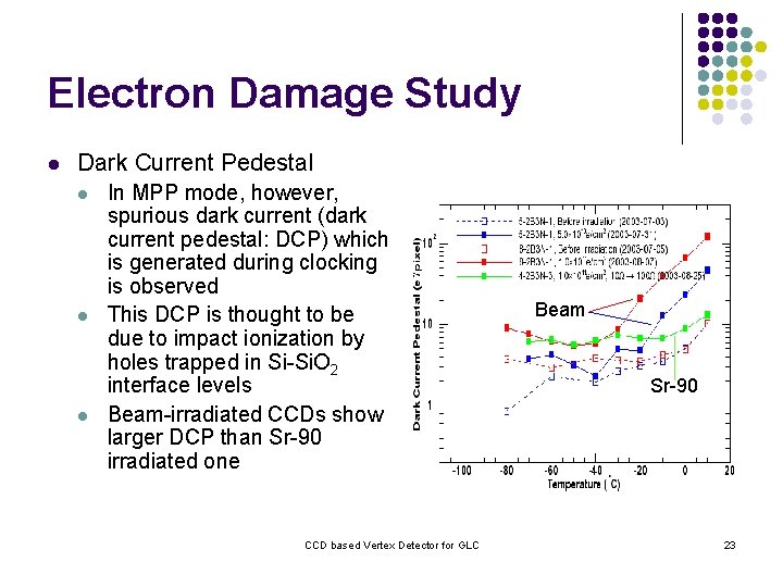
Electron Damage Study l Dark Current Pedestal l In MPP mode, however, spurious dark current (dark current pedestal: DCP) which is generated during clocking is observed This DCP is thought to be due to impact ionization by holes trapped in Si-Si. O 2 interface levels Beam-irradiated CCDs show larger DCP than Sr-90 irradiated one CCD based Vertex Detector for GLC Beam Sr-90 23
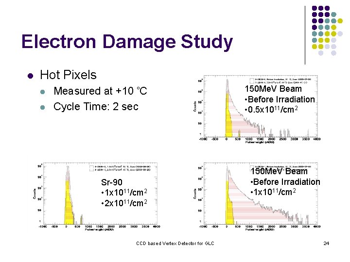
Electron Damage Study l Hot Pixels l l Measured at +10 C Cycle Time: 2 sec Sr-90 • 1 x 10¹¹/cm 2 • 2 x 10¹¹/cm 2 CCD based Vertex Detector for GLC 150 Me. V Beam • Before Irradiation • 0. 5 x 10¹¹/cm 2 150 Me. V Beam • Before Irradiation • 1 x 10¹¹/cm 2 24
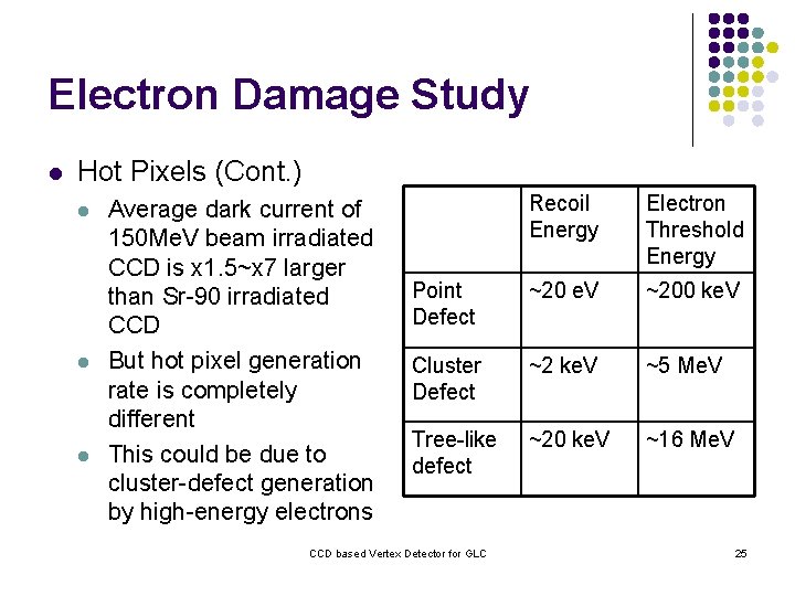
Electron Damage Study l Hot Pixels (Cont. ) l l l Average dark current of 150 Me. V beam irradiated CCD is x 1. 5~x 7 larger than Sr-90 irradiated CCD But hot pixel generation rate is completely different This could be due to cluster-defect generation by high-energy electrons Recoil Energy Electron Threshold Energy Point Defect ~20 e. V ~200 ke. V Cluster Defect ~2 ke. V ~5 Me. V Tree-like defect ~20 ke. V ~16 Me. V CCD based Vertex Detector for GLC 25
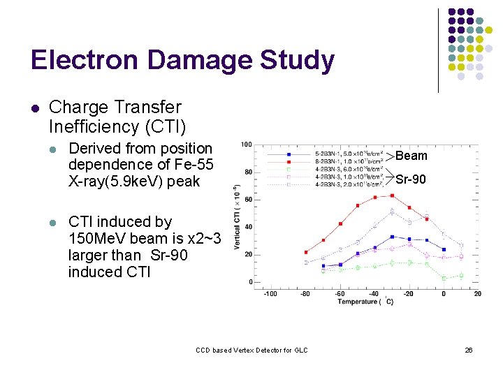
Electron Damage Study l Charge Transfer Inefficiency (CTI) l l Derived from position dependence of Fe-55 X-ray(5. 9 ke. V) peak Beam Sr-90 CTI induced by 150 Me. V beam is x 2~3 larger than Sr-90 induced CTI CCD based Vertex Detector for GLC 26
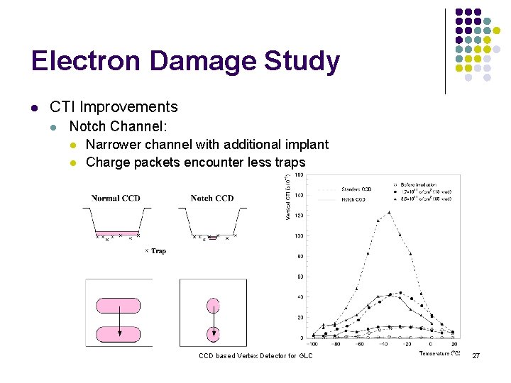
Electron Damage Study l CTI Improvements l Notch Channel: l l Narrower channel with additional implant Charge packets encounter less traps CCD based Vertex Detector for GLC 27
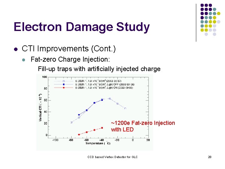
Electron Damage Study l CTI Improvements (Cont. ) l Fat-zero Charge Injection: Fill-up traps with artificially injected charge ~1200 e Fat-zero Injection with LED CCD based Vertex Detector for GLC 28
Electron Damage Study l CTI Improvements (Cont. ) l Wider Vertical Gate Clock & Faster Horizontal Clock CCD based Vertex Detector for GLC 29

Electron Damage Study l CTI Improvements (Cont. ) l l Reduction of number of transfer ( Increase number of output port) Multi Thread CCD (MT-CCD) Expected CTI l Notch channel, f=20 MHz, tw=40 ms, fat-zero=500 e VCTI=2 x 10 -5, HCTI=4 x 10 -6 / 1 x 10¹¹ e/cm 2 @27 C 32(V)x 2000(H) pixels 0. 06%(V), 0. 8%(H) signal loss R=24 mm, B=3 T ~20% signal loss after 50 years R=15 mm, B=4 T ~25% signal loss after 20 years CCD based Vertex Detector for GLC 30
Summary l l We are studying CCD-based vertex detector for GLC(/NLC) which has beam structure favorable for CCD (or any other) vertex detector In order to estimate radiation damage effect by e+/e- pair background at LC, electron damage effects on CCDs are studied for both Sr-90 b and 150 Me. V beam irradiated CCDs. We found : l 150 Me. V electrons cause l l l X 1. 5 ~ x 7 larger bulk dark current than Sr-90 x 2 ~ x 3 larger CTI larger dark current pedestal at higher temperature hot pixels, which cannot be found in Sr-90 irradiated CCD no significant flat-band voltage shift up to 2 x 10¹¹ e/cm 2 irradiation CTI suppression by notch channel and fat-zero injection CCD based Vertex Detector for GLC 31
Summary (cont. ) l l l Using a model calculation, CTI suppression by wider vertical clock and faster horizontal clock has been shown. Combining all the CTI improve methods, and comparing with background simulation, we expect life of CCD-based vertex detector is l ~50 years with R=24 mm, B=3 T (baseline design) l ~20 years with R=15 mm, B=4 T even at room temperature. If CCD is cooled ( < -70 C), CTI becomes still better. Dark current pedestal or hot pixels could put possible limitation for room temperature operation, rather than CTI If the design with R=15 mm is possible, and thinner (~100 mm) wafer is used, impact parameter resolution is improved from sb = 7 20/(pbsin 3/2 q) mm (baseline design) to sb = 5 10/(pbsin 3/2 q) mm, which is the milestone of our R&D. CCD based Vertex Detector for GLC 32
- Slides: 32