Hydro Europe 2012 Consideration of single weirs Consideration


")
 140 120 0, 034 100 0, 05 80 0, 1")
 140 120 Water level computed (TRY 1_HMS 1) weir")
 140 120 100 80 SWL=1 m SWL=2 m observed water")
 140 120 100 Initial. WL=0. 1 m 80 Initial.")


![Change in water level 140 120 Height of water [cm] 100 80 Manning 0.](https://slidetodoc.com/presentation_image_h/00ca41474be565b2381312ecf5727628/image-11.jpg "Change in water level 140 120 Height of water [cm] 100 80 Manning 0.")


: Simulation with initial condition fully dry,")


- Slides: 42
Hydro. Europe 2012
Consideration of single weirs Consideration of whole catchment The Mike 11 point of view concerning influence of factors
Discharges at Napoleon bridge 4500 4000 Manning coefficient Weir coefficient Sea Water Level (swl) Initial Water Level (Initial wl) ANALYSIS WITH TWO DIFFERENT HYDROGRAPHS 3500 3000 discharge in m 3/s 2500 2000 1500 1000 500 0 3/11/94 15: 36 4/11/94 3: 36 4/11/94 15: 36 5/11/94 3: 36 5/11/94 15: 36 6/11/94 3: 36 6/11/94 15: 36 7/11/94 3: 36 7/11/94 15: 36 date Q(observed) (m 3/s) computed TRY 1_HMS 1 computed TRY 1_HMS 2 computed TRY 1_SHE
Change of Manning (HEC-HMS) 140 120 0, 034 100 0, 05 80 0, 1 60 0, 025 40 0, 024 20 observed water level 0 16 10 9 8 7 6 5 4 1 Difference to observed values by changing Manning (HEC-HMS) 2. 5 2 1. 5 0, 034 0, 05 1 0, 025 0. 5 0, 024 0, 04 0 16 -0. 5 -1 10 9 8 7 6 5 4 1
Change of weir coeff (HEC-HMS) 140 120 Water level computed (TRY 1_HMS 1) weir coeff 1. 5<c<3 100 80 Water level computed (TRY 2_HMS 1)weir coeff =1. 7 60 40 observed water level 20 0 16 10 9 8 7 6 5 4 1 Difference to observed values by changing weir coeff (HEC-HMS) 2. 5 2 1. 5 Water level computed (TRY 1_HMS 1) weir coeff 1. 5<c<3 1 Water level computed (TRY 2_HMS 1)weir coeff =1. 7 0. 5 0 16 -0. 5 -1 10 9 8 7 6 5 4 1
Change of SWL (HEC-HMS) 140 120 100 80 SWL=1 m SWL=2 m observed water level 60 40 20 0 16 10 9 8 7 6 5 4 1
Change of Initial WL (HEC-HMS) 140 120 100 Initial. WL=0. 1 m 80 Initial. WL=0. 5 m observed water level 60 40 20 0 16 10 9 8 7 6 5 4 1
Change of Manning coefficient influences the waterlevel- but only small changes In our case there is no logical relation between change of Manning coefficient and waterlevel (in the long profile it probably is different) Sea Water Level and Initial Water Level don‘t cause changes Most changes are caused by weir coefficient Has the greatest influence on hydraulic simulation
Change in water level 140 120 Height of water [cm] 100 80 Manning 0. 024 Manning 0. 034 60 Manning 0. 04 Manning 0. 05 40 20 0 1000 3000 5000 7000 9000 11000 13000 Chainage [m] 15000 17000 19000 21000 23000
Zoom in into the Graph 50 45 40 Water level cm 35 30 Manning 0. 024 25 Manning 0. 034 20 Manning 0. 04 Manning 0. 05 15 10 5 0 12000 14000 16000 chainage m 18000 20000
Investigating a weir upstream
30 Maximum Water Level at Sea Boundary Condition 25 20 0. 1 m Tide Elevation (m)15 0. 3 m Tide 0. 5 m Tide 1. 0 m Tide 10 Channel Bed Bank 5 0 17000 17500 18000 18500 19000 19500 Chainage (m) 20000 20500 21000 21500
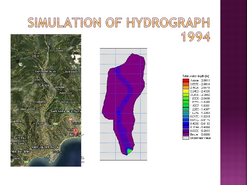
Bathymetry, grid and mesh…
First mesh: Using a coarse mesh and time steps of 30 s Modified mesh: Using finer mesh and time steps of 1 s This in order to keep CFL condition under 0. 8
Influence of: Type of BC Water level, discharge, fluxes, etc. Length Location How to define it?
Upstream Constant discharge tested ranging from 200 to 2000 m 3/s Downstream Constant water level from 0 to 15 meters
Upstream influence of boundary Simulation was initially unstable due to higher elevations that did not allow a proper flow into the domain Change of BC
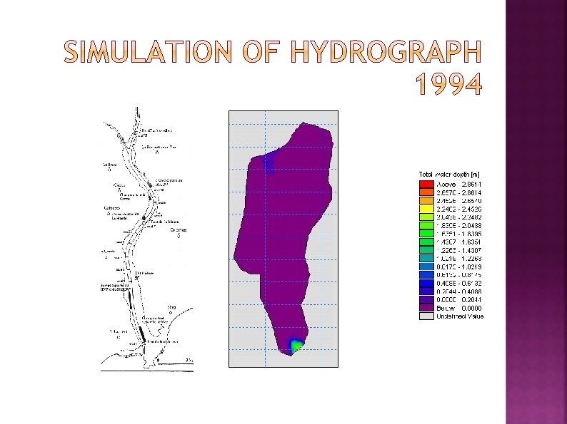
Downstream influence in the model (water elevation): Simulation with initial condition fully dry, BC downstream set to 10 and inlet discharge of 200 m 3/s. Unstable after 4, 4 hours of simulation.
Downstream boundary Below bathymetry: high gradients that produce unstabilities due to velocity At level: similar to case before Above bathymetry: physically reasonable and stable
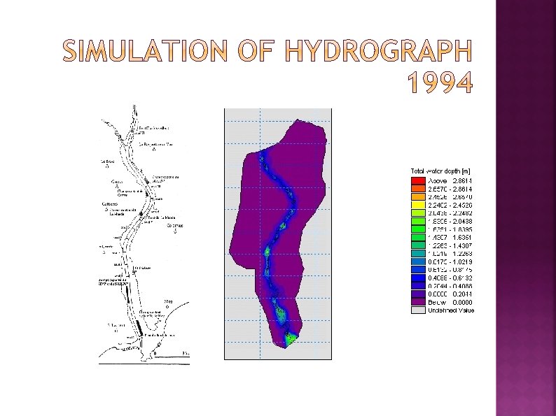
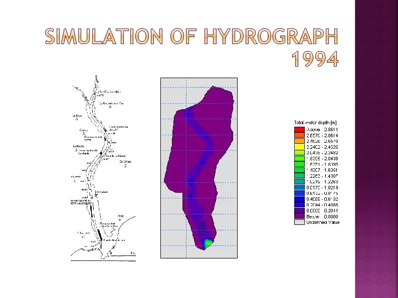
Weir No. 10 Weir No. 4 Weir No. 2 Why Weir No. 2 such small depth? Because it is main flooded area Compared Elevations Weir No. 10 Weir No. 4 1 -D Simulation 3. 05 3. 61 Observed water levels 2. 46 4. 3
Thank you for your attention Hydro. Europe 2012