GSM Security Overview Part 2 Max Stepanov 1

- Slides: 38
GSM Security Overview (Part 2) Max Stepanov 1
Agenda GSM Security Objectives n Concerns, Goals, Requirements GSM Security Mechanisms SIM Anatomy Algorithms and Attacks n n COMP 128 Partitioning Attack on COMP 128 (J. Rao, P. Rohantgi, H. Scherzer, S. Tunguely) 2
GSM Security Concerns Operators n n n Bills right people Avoid fraud Protect Services Customers n n Privacy Anonymity Make a system at least secure as PSTN 3
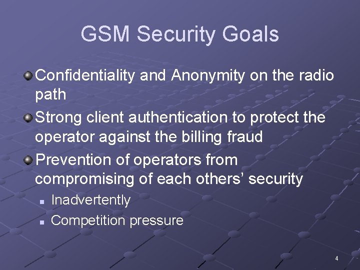
GSM Security Goals Confidentiality and Anonymity on the radio path Strong client authentication to protect the operator against the billing fraud Prevention of operators from compromising of each others’ security n n Inadvertently Competition pressure 4
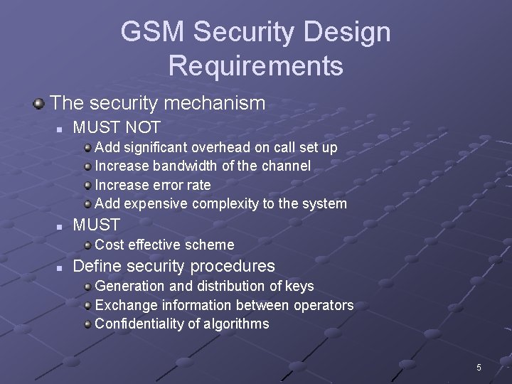
GSM Security Design Requirements The security mechanism n MUST NOT Add significant overhead on call set up Increase bandwidth of the channel Increase error rate Add expensive complexity to the system n MUST Cost effective scheme n Define security procedures Generation and distribution of keys Exchange information between operators Confidentiality of algorithms 5
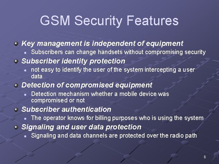
GSM Security Features Key management is independent of equipment n Subscribers can change handsets without compromising security Subscriber identity protection n not easy to identify the user of the system intercepting a user data Detection of compromised equipment n Detection mechanism whether a mobile device was compromised or not Subscriber authentication n The operator knows for billing purposes who is using the system Signaling and user data protection n Signaling and data channels are protected over the radio path 6
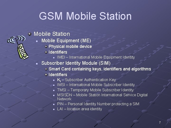
GSM Mobile Station n Mobile Equipment (ME) Physical mobile device Identifiers n n IMEI – International Mobile Equipment Identity Subscriber Identity Module (SIM) Smart Card containing keys, identifiers and algorithms Identifiers n n n Ki – Subscriber Authentication Key IMSI – International Mobile Subscriber Identity TMSI – Temporary Mobile Subscriber Identity MSISDN – Mobile Station International Service Digital Network PIN – Personal Identity Number protecting a SIM LAI – location area identity 7
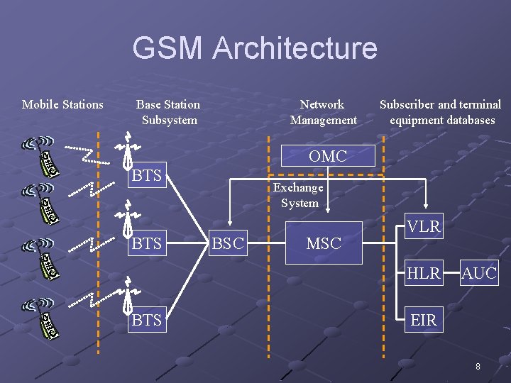
GSM Architecture Mobile Stations Base Station Subsystem Network Management Subscriber and terminal equipment databases OMC BTS Exchange System BSC MSC VLR HLR BTS AUC EIR 8
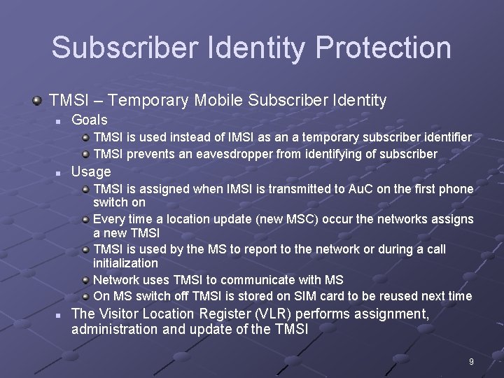
Subscriber Identity Protection TMSI – Temporary Mobile Subscriber Identity n Goals TMSI is used instead of IMSI as an a temporary subscriber identifier TMSI prevents an eavesdropper from identifying of subscriber n Usage TMSI is assigned when IMSI is transmitted to Au. C on the first phone switch on Every time a location update (new MSC) occur the networks assigns a new TMSI is used by the MS to report to the network or during a call initialization Network uses TMSI to communicate with MS On MS switch off TMSI is stored on SIM card to be reused next time n The Visitor Location Register (VLR) performs assignment, administration and update of the TMSI 9
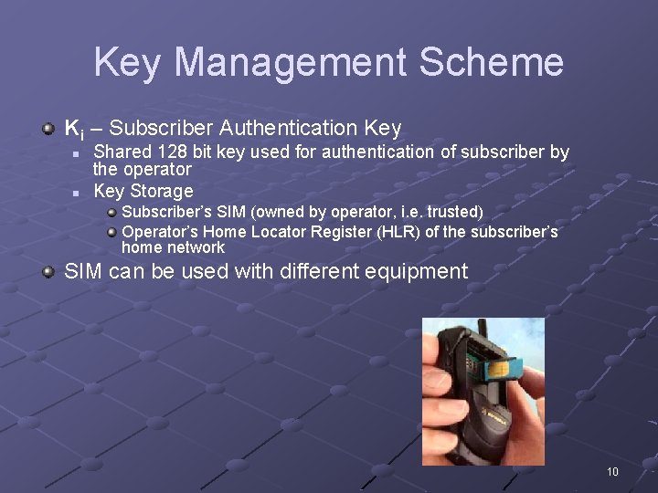
Key Management Scheme Ki – Subscriber Authentication Key n n Shared 128 bit key used for authentication of subscriber by the operator Key Storage Subscriber’s SIM (owned by operator, i. e. trusted) Operator’s Home Locator Register (HLR) of the subscriber’s home network SIM can be used with different equipment 10
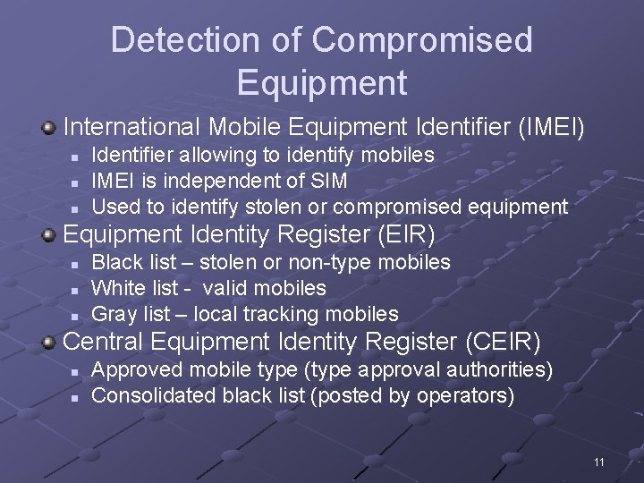
Detection of Compromised Equipment International Mobile Equipment Identifier (IMEI) n n n Identifier allowing to identify mobiles IMEI is independent of SIM Used to identify stolen or compromised equipment Equipment Identity Register (EIR) n n n Black list – stolen or non-type mobiles White list - valid mobiles Gray list – local tracking mobiles Central Equipment Identity Register (CEIR) n n Approved mobile type (type approval authorities) Consolidated black list (posted by operators) 11
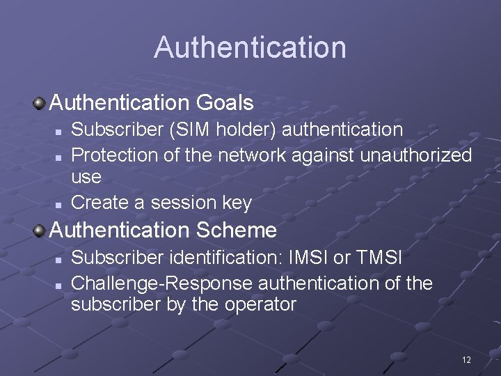
Authentication Goals n n n Subscriber (SIM holder) authentication Protection of the network against unauthorized use Create a session key Authentication Scheme n n Subscriber identification: IMSI or TMSI Challenge-Response authentication of the subscriber by the operator 12
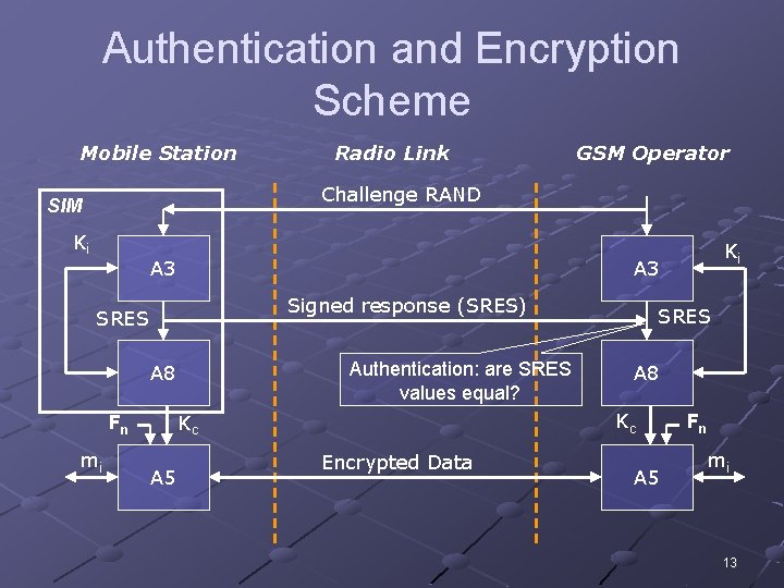
Authentication and Encryption Scheme Mobile Station Radio Link GSM Operator Challenge RAND SIM Ki A 3 Signed response (SRES) SRES Authentication: are SRES values equal? A 8 mi A 5 SRES A 8 Kc Kc Fn Ki Encrypted Data A 5 Fn mi 13
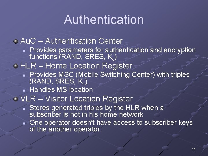
Authentication Au. C – Authentication Center n Provides parameters for authentication and encryption functions (RAND, SRES, Kc) HLR – Home Location Register n n Provides MSC (Mobile Switching Center) with triples (RAND, SRES, Kc) Handles MS location VLR – Visitor Location Register n n Stores generated triples by the HLR when a subscriber is not in his home network One operator doesn’t have access to subscriber keys of the another operator. 14
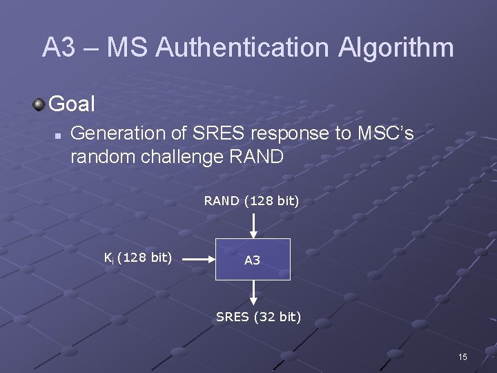
A 3 – MS Authentication Algorithm Goal n Generation of SRES response to MSC’s random challenge RAND (128 bit) Ki (128 bit) A 3 SRES (32 bit) 15
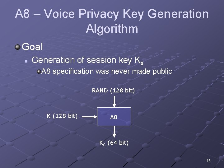
A 8 – Voice Privacy Key Generation Algorithm Goal n Generation of session key Ks A 8 specification was never made public RAND (128 bit) Ki (128 bit) A 8 KC (64 bit) 16
Logical Implementation of A 3 and A 8 Both A 3 and A 8 algorithms are implemented on the SIM n n Operator can decide, which algorithm to use. Algorithms implementation is independent of hardware manufacturers and network operators. 17
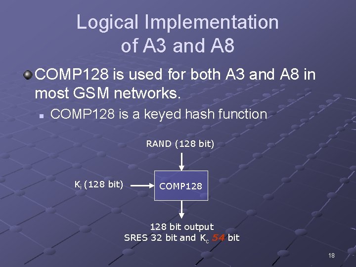
Logical Implementation of A 3 and A 8 COMP 128 is used for both A 3 and A 8 in most GSM networks. n COMP 128 is a keyed hash function RAND (128 bit) Ki (128 bit) COMP 128 bit output SRES 32 bit and Kc 54 bit 18
A 5 – Encryption Algorithm n A 5 is a stream cipher Implemented very efficiently on hardware Design was never made public Leaked to Ross Anderson and Bruce Schneier n Variants A 5/1 – the strong version A 5/2 – the weak version A 5/3 n n GSM Association Security Group and 3 GPP design Based on Kasumi algorithm used in 3 G mobile systems 19
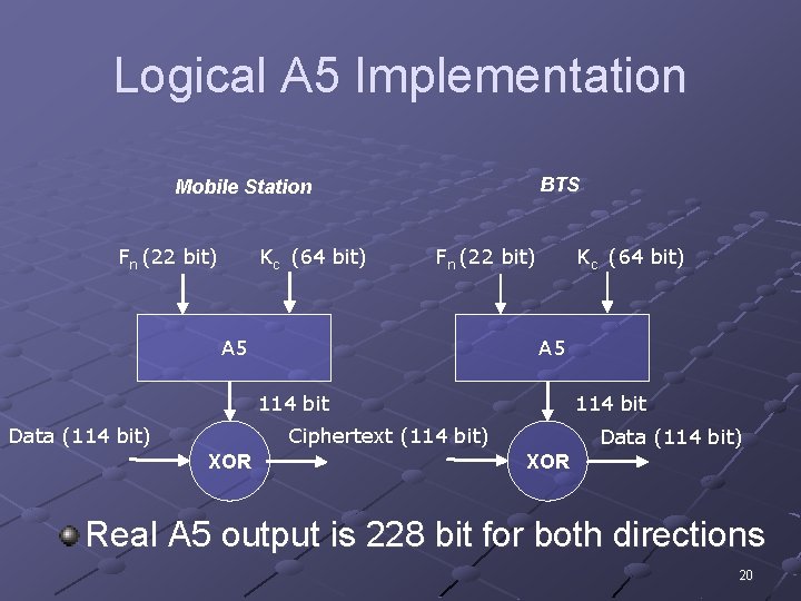
Logical A 5 Implementation BTS Mobile Station Fn (22 bit) Kc (64 bit) Fn (22 bit) A 5 Kc (64 bit) A 5 114 bit Data (114 bit) 114 bit Ciphertext (114 bit) XOR Data (114 bit) XOR Real A 5 output is 228 bit for both directions 20
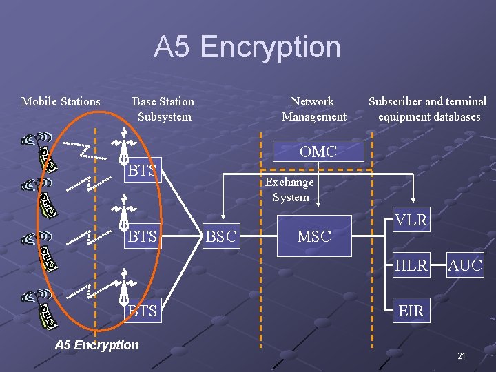
A 5 Encryption Mobile Stations Base Station Subsystem Network Management Subscriber and terminal equipment databases OMC BTS Exchange System BSC MSC VLR HLR BTS A 5 Encryption AUC EIR 21
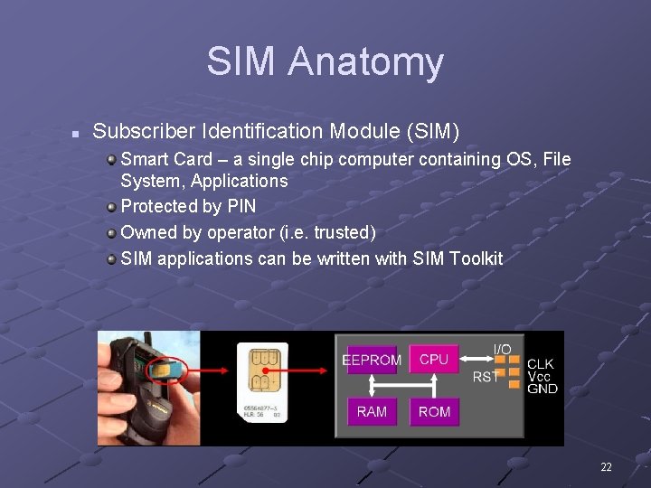
SIM Anatomy n Subscriber Identification Module (SIM) Smart Card – a single chip computer containing OS, File System, Applications Protected by PIN Owned by operator (i. e. trusted) SIM applications can be written with SIM Toolkit 22
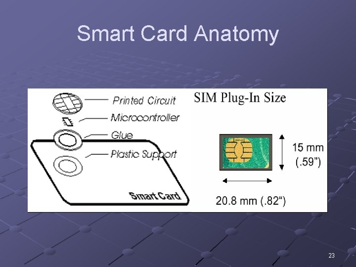
Smart Card Anatomy 23
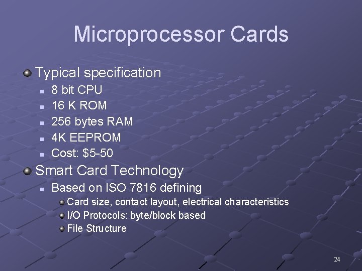
Microprocessor Cards Typical specification n n 8 bit CPU 16 K ROM 256 bytes RAM 4 K EEPROM Cost: $5 -50 Smart Card Technology n Based on ISO 7816 defining Card size, contact layout, electrical characteristics I/O Protocols: byte/block based File Structure 24
Algorithm Implementations and Attacks 25
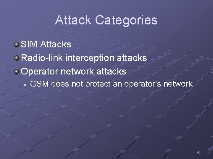
Attack Categories SIM Attacks Radio-link interception attacks Operator network attacks n GSM does not protect an operator’s network 26
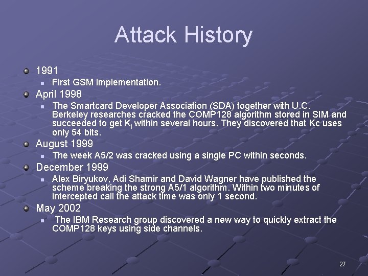
Attack History 1991 n First GSM implementation. April 1998 n The Smartcard Developer Association (SDA) together with U. C. Berkeley researches cracked the COMP 128 algorithm stored in SIM and succeeded to get Ki within several hours. They discovered that Kc uses only 54 bits. August 1999 n The week A 5/2 was cracked using a single PC within seconds. December 1999 n Alex Biryukov, Adi Shamir and David Wagner have published the scheme breaking the strong A 5/1 algorithm. Within two minutes of intercepted call the attack time was only 1 second. May 2002 n The IBM Research group discovered a new way to quickly extract the COMP 128 keys using side channels. 27
COMP 128 Keyed hash function 28
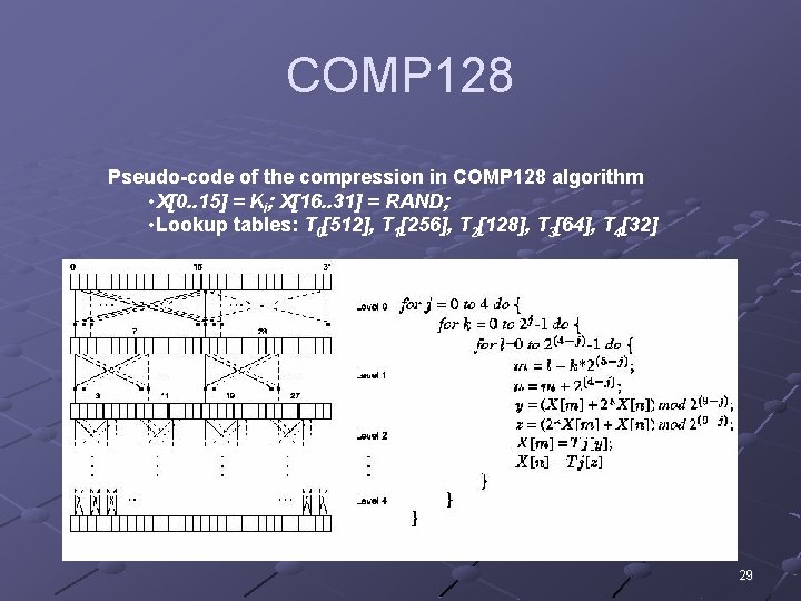
COMP 128 Pseudo-code of the compression in COMP 128 algorithm • X[0. . 15] = Ki; X[16. . 31] = RAND; • Lookup tables: T 0[512], T 1[256], T 2[128], T 3[64], T 4[32] 29
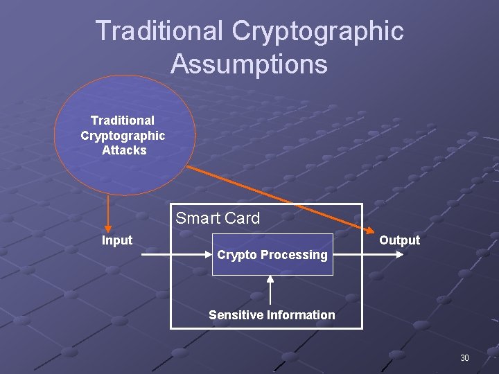
Traditional Cryptographic Assumptions Traditional Cryptographic Attacks Smart Card Input Output Crypto Processing Sensitive Information 30
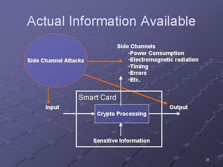
Actual Information Available Side Channels • Power Consumption • Electromagnetic radiation • Timing • Errors • Etc. Side Channel Attacks Smart Card Input Output Crypto Processing Sensitive Information 31
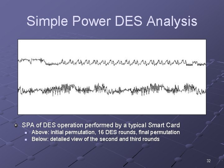
Simple Power DES Analysis SPA of DES operation performed by a typical Smart Card n n Above: initial permutation, 16 DES rounds, final permutation Below: detailed view of the second and third rounds 32
Partitioning Attack on COMP 128 Attack Goal n n Ki stored on SIM card Knowing Ki it’s possible to clone SIM Cardinal Principle n Relevant bits of all intermediate cycles and their values should be statistically independent of the inputs, outputs, and sensitive information. Attack Idea n n Find a violation of the Cardinal Principle, i. e. side channels with signals does depend on input, outputs and sensitive information Try to exploit the statistical dependency in signals to extract a sensitive information 33
Partitioning Attack on COMP 128 How to implement 512 element T 0 table on 8 bit Smart Card (i. e. index is 0. . 255)? Split 512 element table into two 256 element tables It’s possible to detect access of different tables via side channels! n n Power Consumption Electromagnetic radiation 34
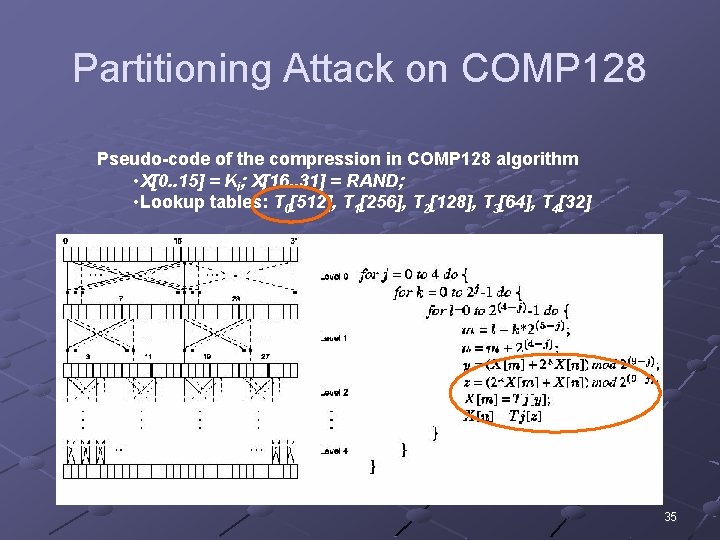
Partitioning Attack on COMP 128 Pseudo-code of the compression in COMP 128 algorithm • X[0. . 15] = Ki; X[16. . 31] = RAND; • Lookup tables: T 0[512], T 1[256], T 2[128], T 3[64], T 4[32] 35
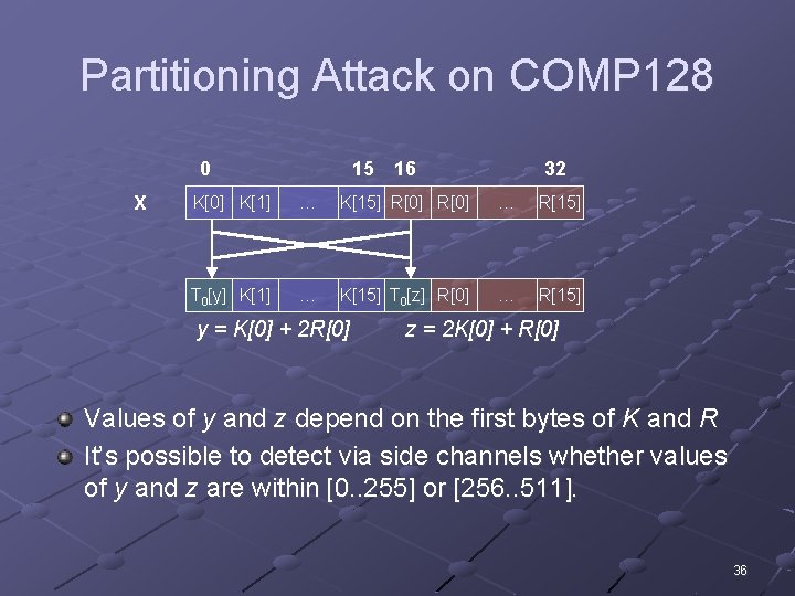
Partitioning Attack on COMP 128 0 X 15 16 32 K[0] K[1] … K[15] R[0] … R[15] T 0[y] K[1] … K[15] T 0[z] R[0] … R[15] y = K[0] + 2 R[0] z = 2 K[0] + R[0] Values of y and z depend on the first bytes of K and R It’s possible to detect via side channels whether values of y and z are within [0. . 255] or [256. . 511]. 36
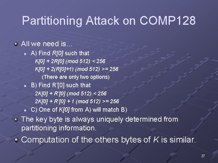
Partitioning Attack on COMP 128 All we need is… n A) Find R[0] such that K[0] + 2 R[0] (mod 512) < 256 K[0] + 2(R[0]+1) (mod 512) >= 256 (There are only two options) n B) Find R’[0] such that 2 K[0] + R’[0] (mod 512) < 256 2 K[0] + R’[0] + 1 (mod 512) >= 256 n C) One of K[0] from A) will match B) The key byte is always uniquely determined from partitioning information. Computation of the others bytes of K is similar. 37
Summary GSM Security Objectives n Concerns, Goals, Requirements GSM Security Mechanisms SIM Anatomy Algorithms and Attacks n n COMP 128 Partitioning Attack on COMP 128 38