GNITC GURU NANAK INSTITUTIONS TECHNICAL CAMPUS DEPARTMENT OF

 WATER RESOURCES ENGINEERING -")

 2. Connate water or")


")


 hydrochloric")


- Slides: 85
GNITC GURU NANAK INSTITUTIONS TECHNICAL CAMPUS DEPARTMENT OF CIVIL ENGINEERING WATER RESOURCES ENGINEERING-I CLASS ROOM LECTURES By Dr. M. K. Mohan B. E, M. E, Ph. D, MISTE, MISCA, Professor of Civil Engineering & Member of Illuminati of IBC, Cambridge, England WRE I – Unit III - Ground Water September, 2015
JAWAHARLAL NEHRU TECHNOLOGICAL UNIVERSITY HYDERABAD R 13 Syllabus (A 50122) WATER RESOURCES ENGINEERING - I UNIT III Ground water Occurrence, types of aquifers, aquifer parameters, porosity, specific yield, permeability, transmissibility and storage coefficient, Darcy’s law, radial flow to wells in confined and unconfined aquifers. Types of wells – Well Construction – Well Development
GROUND WATER 1. Ground water may be defined as water that occurs below the surface of earth. 2. Ground water hydrology is defined as the science of study of the occurrence, distribution and movement of water below the surface of earth. 3. Ground water levels may be found in major metropolitan areas at a depth ranging from 7 m to 12 m (20 ft to 40 ft)
GROUND WATER OCCURRENCE Sources of Ground Water 1. Precipitation (major) 2. Connate water or fossil water or primitive water (minor) 3. Juvenile water (minor) Precipitation: Part of the water falling on the earth surface is infiltrated into earth surface, percolates down and reaches the Ground water table. Connate water or fossil water or interstitial water : Water present in the rock at the time of its formation is known as connate water. It is highly saline. It is also known as fossil water or interstitial water. Juvenile water or primitive water : is formed chemically within the earth. It is present in a very small quantity and is also known as primitive water.
Ways of Ground water Extraction 1. Natural way: Natural discharge occurs as flow in lakes, reservoirs, rivers, oceans and springs. 2. Artificial way: By pumping from wells
CLASSIFICATION OF ROCKS BASED ON POROSITY AND PERMEABILITY Based on porosity and permeability characteristics, rocks are classified into 4 types. 1. Aquifer 2. Aquifuge 3. Aquiclude 4. Aquitard
CLASSIFICATION OF ROCKS BASED ON POROSITY AND PERMEABILITY 1. Aquifers are those geological formations which are porous and permeable. They contain water and transmit water to pass through them. 2. Aquifuges are those geological formations which are non-porous and impermeable. They neither contain water nor transmit water to pass through them. 3. Aquicludes are those geological formations which are porous but not permeable. They contain water but not transmit water to pass through them. 4. Aquitards are special type of aquifuges and aquicludes in which they transmit water due to
Zones of Ground Water There are two major zones of Ground water 1. Zone of aeration (unsaturated zone): The area lying above ground water table is known as zone of aeration. This is unsaturated zone. This includes soil water zone and intermediate zone. 2. Zone of saturation: Ground water fills all the interstices in the saturated zone. The top surface of zone of saturation is called Ground water table: The interface between zone of aeration and zone of saturation is called ground water table.
Zone of aeration is further sub-divided into 3 zones. 1. Soil water zone : It contains soil moisture. 2. Intermediate zone : It contains pellicular and gravitational water. 3. Capillary zone : It contains capillary water.
TYPES OF Aquifers are classified into 3 types AQUIFERS 1. Unconfined aquifer 2. Confined aquifer 3. Perched aquifer Unconfined aquifer: An aquifer where the water table is the upper surface limit and extends below till the impermeable rock strata is called unconfined aquifer. Confined aquifer: When an aquifer is sandwiched between two impermeable layers, it is known as confined aquifer. It will not have a free water table and the aquifer will be under pressure. Perched aquifer: Perched aquifer is a special type of unconfined aquifer, and occurs where a ground water body is separated from the
UNCONFINED AQUIFER An aquifer, where the water table is the upper surface limit and extends below till the impermeable rock strata is called unconfined aquifer.
CONFINED AQUIFER an aquifer is sandwiched between two impermeable When layers, it is known as confined aquifer. It will not have a free water table and the aquifer will be under pressure.
Perched aquifer and Perched water table is a special type of unconfined aquifer, and Perched aquifer occurs where a ground water body is separated from the main ground water by a relatively impermeable stratum of small areal extent and by the zone of aeration above the main body of the ground water.
WATER TABLE WELL AND ARTESIAN WELL Water table well: When well is dug into the unconfined aquifer, it is known as water table well. Artesian Well: When a well is dug into the confined aquifer, it is known as artesian well. Artesian spring well or Artesian flowing well: When a well penetrates a confined aquifer, water rises in the well to the level of its piezometric head and if this piezometric level lies above the ground surface, water shoots on to the surface of earth and this type of well is called as Artesian spring well. Artesian non-flowing well: When a well penetrates a confined aquifer, water rises in the well to the level of its piezometric head and if this piezometric level lies below the ground surface, then this type of well is called as Artesian spring well.
WATER TABLE WELL AND ARTESIAN WELL
AQUIFER PARAMETERS SPECIFIC YIELD
AQUIFER PARAMETERS SPECIFIC RETENTION
AQUIFER PARAMETERS POROSITY
RELATIONSHIP BETWEEN POROSITY, SPECIFIC YIELD AND SPECIFIC RETENTION
AQUIFER PARAMETERS Coefficient of Transmissibility “T” It is defined as the rate of flow of water (in m 3/day) through a vertical strip of aquifer of unit width (1 m or 1 ft) and extending the full saturation height under unit hydraulic gradient, at a temperature of 60 OF. T= kb Where T = Coefficient of Transmissibility k = Coefficient of Permeability b = Width of confined aquifer
AQUIFER Storage. PARAMETERS coefficient The water yielding capacity of a confined aquifer can be expressed in terms of its storage coefficient. Storage coefficient is defined as the volume of water that an aquifer releases from or takes into storage per unit surface area of aquifer per unit change in the component of head normal to that surface. Storage coefficient = Volume of water released by an aquifer / Unit surface area of aquifer per unit change in component of head normal to it
Well Hydraulics For laminar flow conditions a saturated soil, the rate DARCY’Sin. LAW of flow or discharge per unit area is proportional to hydraulic gradient q α i q = ki or Q=ki. A or V = ki Where Q = discharge in cumecs q = Q/A = discharge per unit area k = coefficient of permeability i = hydraulic gradient
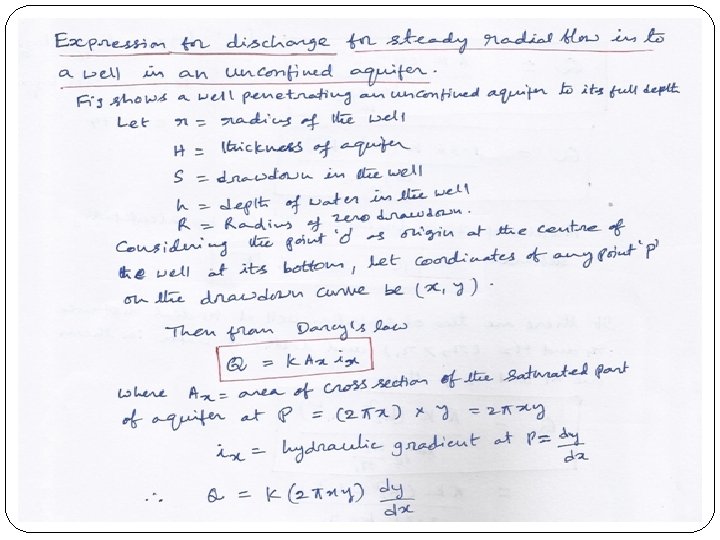
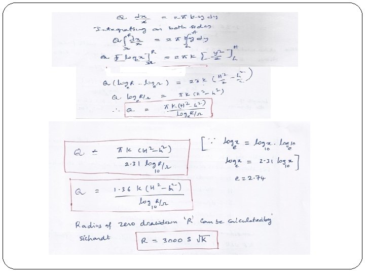
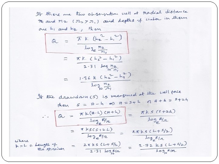
STEADY RADIAL FLOW TO A WELL IN AN UNCONFINED AQUIFER: DUPUIT’S THEORY
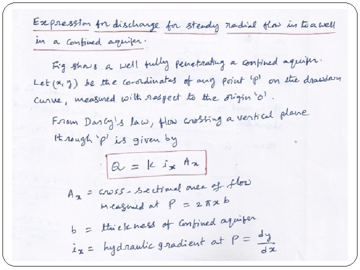
STEADY RADIAL FLOW TO A WELL IN A CONFINED AQUIFER: DUPUIT’S THEORY
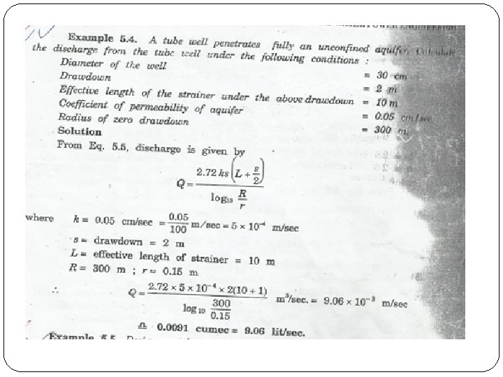
ASSUMPTIONS IN DUPUIT’S THEORY 1. The flow is steady, laminar and Darcy’s law is applicable. 2. The flow is horizontal and uniform every where in the vertical section. 3. Aquifer is homogeneous, isotropic and of infinite areal extent. 4. The well penetrates and receives water from the entire thickness of the aquifer. 5. The coefficient of Transmissibility is constant at all places and at all times. 6. Natural ground water regime affecting an aquifer remains constant with time
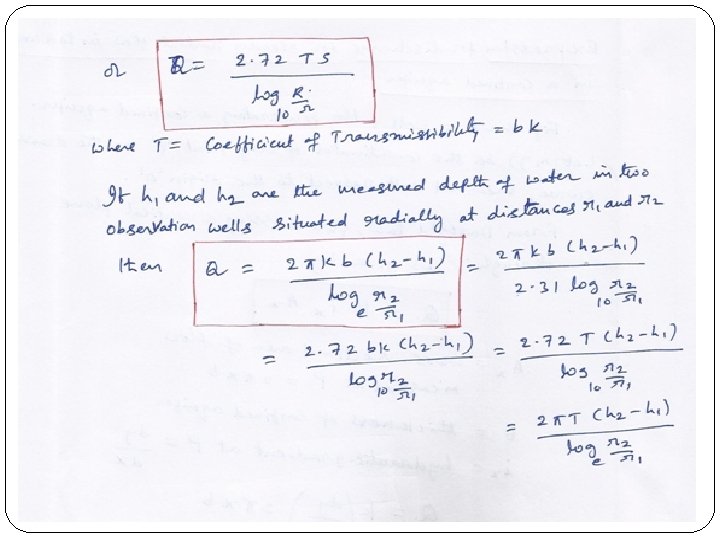
Determination of Aquifer Constant for Confined Aquifer
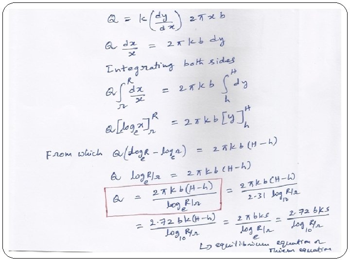
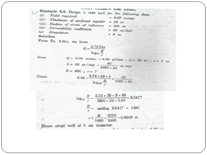
Determination of Aquifer Constant for Unconfined Aquifer
CHARACTERISTIC WELL LOSSES Well Loss: When water is pumped out of a well, the total drawdown caused includes not only that of the logarithmic drawdown curve at the well face, but also drawdown caused by flow through well screen and axial movement within the well. The drawdown caused by flow through well screen and axial movement within the well is called Well Loss. Since turbulent flow generally occur near the well face, this loss may be taken to be proportional to Qn. Adding well loss to the drawdown, s can be written as
SPECIFIC CAPACITY OF A WELL The specific capacity of a well is the measure of the effectiveness of the well, and is defined as the yield of the well per unit drawdown. If s = drawdown and Q = well discharge or the yield
INTERFERENCE AMONG Topic outside syllabus WELLS If the two wells are a distance B apart, and have the same diameter and drawdown and discharge over the same period of time, it can be shown with the help of method of complex variables, that the discharge through each well is given by If there are 3 wells forming an equilateral triangle a distance B on a side, and if all the three wells have the same characteristics If there were only one well , then the discharge under the same drawdown, would have been
Combined Artesian Gravity Well In an artesian well, due to high pumping, some times the water level at well face may go down below the top of confined aquifer. In such case, the flow pattern close to the well is similar to that for a gravity well whereas at distances farther from This type of well is known as a combined artesian gravity well, the flow pattern is The flow from such a well can be computed from the following artesian. expression developed by Muskat.
Partially Penetrating Artesian Well Topic outside syllabus A partially penetrating artesian well is the one in which the well screen does not penetrate to the full depth of the confined aquifer. The discharge Qp from such a well is computed from the following formula Where Qp = discharge for partially penetrating well, Q = discharge for a fully penetrating well for the same drawdown (H-h), G = correction factor for partial penetration = QP/Q Correction factor G can be obtained from the following expression developed by Kozeny.
WELL S Well : A well is a structure constructed for the purpose of drawing ground water from the surface. It is a hole or a shaft usually vertical excavated in ground for bringing ground water to the surface. (Shaft here means a narrow vertical passage. )
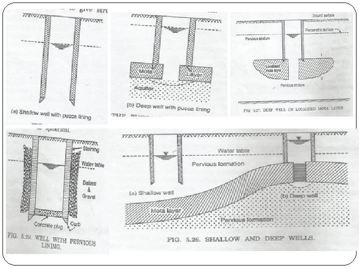
TYPES OF WELLS Wells are of 2 types. 1. Open wells (or Dug wells) i. Shallow well ii. Deep well 2. Tube wells (or Bore wells or Drilled wells. ) i. Strainer well ii. Cavity well iii. Slotted well
OPEN WELLS Open well is essentially of bigger diameter than that of tube well and derives its water from one pervious stratum only. It is 2 -13 m in diameter and generally less than 20 m depth. It is dug into the ground to tap water from one pervious stratum only. The walls of open wells are generally are built of precast concrete rings or in brick or stone masonry. It is suitable for discharge up to 0. 005 cumecs. The thickness of walls will be around 0. 45 to 0. 75 m. They have uniform cross section of circular or square. Water can be withdrawn safely only at or below the critical velocity of soil. Higher velocities cannot be permitted as that may lead to disturbance of soil grains and
TYPES OF OPEN WELLS 1. Shallow well is one which rests in a pervious stratum and draws its supply from the surrounding material. 2. Deep well is the one which rests on an impervious layer and draws its supply from the pervious formation below it (confined aquifer). The water level in a deep well is equal to the piezometric head in the water bearing strata. Normally deep wells are located at a greater depth compared to shallow wells. However, some times a deep well may be located at a shallow depth compared to shallow well depending on the structure of underlying geological formation.
Tube well is a long pipe sunk into the groundwhich allows water to pass through it intercepting more than one stratum. They are also called as Bore wells or drilled wells. The bore wells diameter will be in the range of 8 to 10 cm. The depth of excavation will be up to 75 m or even beyond. Because of the strainer, high velocity of flow can be permitted without danger of soil particles being carried away with water. Also because of radial flow towards the well, the c/s area of flow is more. Due to increased velocity and more c/s area of flow, a tube well though much less in diameter than open well, gives discharge many times more than the open well.
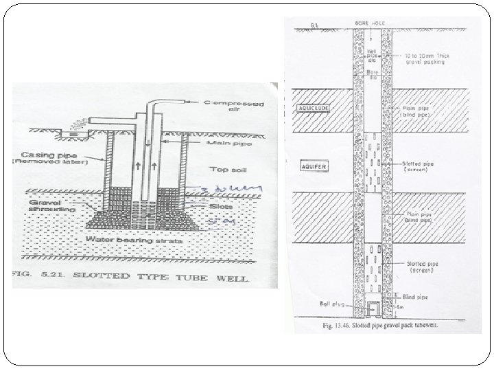
TYPES OF TUBE WELLS There are 3 types of tube wells. i. Strainer well ii. Cavity well iii. Slotted well
Strainer well is a most common and widely used drilled well which derives water from several aquifer formations. A tube with a number of openings is sunk into the ground to which a wire mesh is wrapped round the tube. The area of openings of wire mesh will be equal to the area of openings of tube. The flow is radial. A strainer, which is a special type of wire mesh, is wrapped round the main tube of the well. The main pipe contains bigger holes than the openings of the strainer. Total area of the openings of the tube is kept equal to the openings of the strainer so that the velocity of flow does not change. The mesh size of strainer is generally kept equal to D 60 to D 70 of the surrounding soil. Sufficient space is left between wire mesh and pipe so that the effective area of pipe is not reduced. At the bottom a short pipe is provided to permit settlement of any sand if passed through the strainer.
Strainer well
Cavity well 1. This is a special type of tube well in which water is not drawn through the strainer but it is drawn through the bottom of the well where a cavity is formed and the flow is spherical. 2. The tube well pipe penetrates a strong clay layer which acts as a strong roof. 3. Water can be withdrawn from one aquifer layer only. 4. The cavity tube well is more or less similar to a deep well. 5. The essential condition for a cavity tube well to function efficiently is to have confined aquifer of good specific yield, and the aquifer should have a strong impervious material above it. 6. In the initial stage of pumping with the help of a centrifugal pump, fine sand comes with water and consequently a hollow cavity is formed. 7. As the spherical area of cavity increases outwards, the
Cavity well
Slotted well It is a type of well in which slotted tube is penetrated into the water bearing stratum up to some depth penetrating in to the confined aquifer. If water bearing stratum is available at a depth greater than 100 m then this kind of well is used. A slotted tube well consists of a slotted tube penetrating the confined aquifer. The size of slots is 25 mm x 3 mm and are provided at 10 to 12 mm spacing. Slots are provided up to a height of 5 m. The adjoining area of the pipe should be shrouded up to a height of 3 to 4 m above top of slot to prevent the fine particles entering the pipe. Water can be drawn from more than one aquifer formations. A casing pipe of 36 cm dia is lowered and soil is excavated out. The main pipe is of 15 cm dia is then lowered, the slotted portion being only 5 m long and the rest of the length being plain pipe.
WELL CONSTRUCTION Methods of Drilling Tube Wells: 1. 2. 3. 4. Wash boring or water jet boring method Cable tool method Hydraulic rotary method Reverse rotary method
Wash boring or water jet boring method 1. This method is suitable for soft foundations consisting of gravel, sand, clay or other soft deposits. 2. The boring is done by cutting action of downward directed stream of water. 3. The outer casing is first erected in position in a suitable pit dug at the surface. 4. A jet pipe with a nozzle is then lowered in the casing tube, and water under pressure is forced through it. 5. The dislodged soil particles and broken pieces form slurry with water and are lifted up through annular space between the casing and jet pipe by the returning water in the upward direction.
Wash boring or water jet boring method
Cable tool method or Percussion drilling method 1. This method is used for drilling through consolidated rock formations. 2. In this method, a standard well drilling rig consists of 1) a multi-line hoist 2) a walking beam 3) and an engine all the above assembled and mounted on a truck 3. A string of percussion tools consisting of 1) a rope socket 2) a set of jars 3) a drill stem 4) a drilling bit total weight of the above several thousand kilograms drilling bit alone weighs 1500 kg and 1 to 3 m length.
Cable tool method or Percussion drilling method Procedure: 1. A pit is dug at the site where well is to be drilled. 2. A casing pipe, with a drive shoe is inserted in the pit. 3. The string of drilling tools is inserted in the first length of the casing pipe. 4. Drilling is then accomplished by regular lifting and dropping of the string of tools mechanically. 5. During drilling, the tools make 40 to 60 strokes per minute, ranging from 40 cm to 1 m in length. 6. The drilling is kept continuously rotated so that the drilling bit will form a round hole. 7. After the bit has cut 1 to 1. 5 m through the formation, the string of tools are taken out and a bailer is inserted in the hole to remove the drill cutting. 8. Bailer consists of pipe like section with a valve at the bottom.
Cable tool method or Percussion drilling method
Hydraulic rotary method or Rotary boring method 1. This method is used for drilling large bores in unconsolidated strata. 2. This is fastest method and has been used for wells of 45 cm dia and for depth over 163 m. Oil wells over 7000 m deep have been drilled by this method. 3. In this method, the boring is done with the help of a drilling bit attached at the end of a string of hollow pipe. 4. A mixture of clay and water, known as drilling mud, is continuously circulated through drill shaft in the hole. 5. Material loosened by the bit is carried upward in the hole by the rising mud. 6. Ordinarily no casing is required since the drilling mud forms a clay lining and supports the walls of hole.
Hydraulic rotary method
Reverse rotary 1. A modification method of the hydraulic rotary method is known as the reverse rotary method. 2. It is used in Europe and is gaining popularity now a days. 3. It is quite useful for making large wells of diameter up to 1. 2 m in unconsolidated formations. 4. The tools consist of a hollow drill, a drill pipe and water swivel. 5. In this method, the cuttings are removed by water through a suction pipe called drill pipe. 6. The equipment consists of a mast or a derrick, a centrifugal pump, necessary water and power arrangement and the requisite casing pipe. 7. The hole is driven by pumping water under pressure through the drilling bit. 8. A large capacity suction pipe is used for this method. 9. A large capacity centrifugal pump is used to pump out the
Reverse rotary method
WELL DEVELOPMENT Well development is the process of removing fine material from the aquifer formation surrounding the strainer pipe. The main objectives of well development are: 1. To increase the specific capacity of well 2. Preventing sand flowing in 3. Obtaining maximum economic life 4. To unclog the water bearing formation 5. To increase the porosity and permeability of formation 6. To stabilised the sand formation around a screened well, so that the well may yield sand free water. 7. Actual yield of well can be known only after well development 8. It also helps in determining the requiring characteristics of the pump and power units to be installed.
Methods of Well Development There are 5 methods of well development 1. 2. 3. 4. 5. Development by pumping Development by surging Development by compressed air Development by back washing Development by dry ice.
Development by pumping 1. In this method, a variable speed pump is used. 2. The method is based on the principle that irregular and non -continuous pumping agitates the fine material surrounding the well so that it can be carried into the well and pumped out. 3. Initially the pump is started with a very low discharge. The fine particles start coming. 4. This low speed is maintained till clear water comes. 5. The discharge is then increased in steps until maximum discharge or well capacity is reached. 6. The pump is then stopped and levels permitted to increase till it comes to normal. 7. The pump is then again started and the procedure repeated, till no fine particles come.
Development by surging 1. In this method, surging effect is created by up and down movement of a hollow surge block or a bailer. 2. Calgon (Sodium hexametaphosphate) is added to water so that it acts as a dispersing agent for fine grained particles. 3. When the surge block is moved up it sucks water in 4. When it is moved down, it forces water-calgon solution back in the formation. 5. Further upward motion brings with it fine material. 6. The surge block is connected to a string of hollow pipe from which the water charged with fine particles is pumped out continuously. 7. The procedure is repeated by increasing the speed of surging till clear water comes out.
Development by compressed air 1. In this method, the development is done with the help of an air compressor, a discharge pipe and air pipe. 2. The air pipe is put into the discharge pipe and is lowered into the well tube, till the assembly reaches near the bottom of the strainer-pipe section. 3. The lower end of the air pipe is kept emerging out of the discharge pipe by a small length. 4. The air entry to the air pipe is first closed and the compressor is then started till a pressure of 6 to 10 kg/cm 2 is built up. 5. The air is then suddenly made to enter the pipe, at this pressure, with the help of a suitable quick opening valve. 6. This sudden entry of air into well creates a powerful surge with in the well causing loosening of fine material surrounding the perforations.
Development by compressed air 7. When pressure decreases, water enters the well bringing the loosened particles with it. 8. The continuous air injection creates an air lift pump, and the water carrying fine particles is pumped out. 9. The process is repeated till clear water comes. 10. The pipe assembly is then lifted up, and the surging is again created. 11. This operation is repeated at interval along the screen section till the well is fully developed.
Development by back washing 1. In this method in addition to i. the compressor ii. the discharge pipe iii. Long air pipe and in addition to the above, a small air pipe is used. 2. The well is sealed at its top so that it becomes air tight. 3. The discharge and air pipe assembly is lowered in the well. 4. A small air pipe is fitted at the top of the air-tight cover, and is provided with a 3 way cock. 5. With the help of a 3 way cock, air can be admitted to well either through the long air pipe or through the small air pipe fitted at the top. 6. Air is first made to enter the long air pipe. 7. This forces air and water out of the well through the discharge pipe. 8. When clear water comes, the valve is closed, and water
Development by back washing 9. The valve is then turned to the other side so that air enters through the small air pipe. 10. This back washes the water from the well through the discharge pipe and at the same time agitates the fine particles surrounding the well. 11. Calgon is often added to the water. 12. When air starts escaping from the discharge pipe, the valve is turned so that air enters the long air pipe, so that assembly works out an air-lift pump and the water is pumped out. 13. The procedure is repeated till clear water comes and the well is finely developed.
Development by dry ice 1. In this method, two chemicals are used 1) hydrochloric acid 2) Solid carbon dioxide (dry ice) 2. First of all, hydrochloric acid is poured into the well. 3. The well is capped at the top and compressed air is forced into the well. 4. The pressure of compressed air forces the chemical into the formation. 5. The cap is then removed and blocks of dry ice are dropped into the well. 6. Sublimation releases gaseous carbon dioxide and a high pressure of this gas is built up in the well. 7. On releasing the pressure, the muddy water is forced up in the form of a jet and is automatically thrown out of the well.
WELL SHROUDING shrouding is a process Topic outside syllabus 1. Well of interposing coarse material such as gravel and coarse sand between the well pipe (strainer pipe) and the aquifer soil to prevent finer particles of soil coming in contact with the strainer and chocking it. 2. This is essential in sandy and unconsolidated formations of aquifer. 3. This is also essential in slotted type of tube well where a strainer is not used. 4. A minimum thickness of 40 cm gravel pack is necessary to make it effective. 5. Slotted type well some times is also known as gravelpacked well. 6. The shrouding increases the effective well diameter 7. The shrouding acts as a strainer 8. It increases the specific capacity of well.
INFLUENT AND EFFLUENT STREAM CONDITIONS Influent Stream: When a stream supplies water to the Ground water table, it is called Influent stream. Effluent Stream: When a stream receives water from the Ground water table, it is called Effluent stream.
Yield of an Open well Topic outside syllabus The yield of a open well can be found out experimentally by conducting following tests. 1. Constant level pumping test 2. Recuperation test
1. 2. 3. 4. 5. Topic outside CONSTANT LEVEL PUMPING syllabus TEST In this test, a pump with suitable regulating arrangement is used. The water level is depressed by an amount ‘h’ known as depression head. The speed of the pump is so adjusted that whatever enters the well under this depression head is pumped out and a constant water level is maintained in the well. The amount of water pumped out is measured with the help of a V-notch or any other arrangement, in a given amount of time for which the pump speed was regulated to a constant value. The quantity of water pumped out in one hour gives the yield of the well per hour.
CONSTANT LEVEL PUMPING TEST Topic outside syllabus
RECUPERATION TEST Topic outside syllabus 1. In recuperation test, water level is depressed to any level below the normal and the pumping is stopped. 2. The time taken for the water to recuperate to the normal level is noted. 3. The discharge from the well is calculated using the formula
RECUPERATION TEST Topic outside syllabus
ASSIGNMENT QUESTIONS
ASSIGNMENT QUESTIONS
ASSIGNMENT QUESTIONS
TEXT BOOKS 1. Engineering Hydrology by Jayaram Reddy, Laxmi publications pvt. Ltd. , New Delhi 2. Irrigation and water power engineering by Punmia & Lal, Laxmi publications pvt. Ltd. , New Delhi
REFERENCE BOOKS 1. Elementary hydrology by V. P. Singh, PHI publications. 2. Irrigation and Water Resources & Water Power by P. N. Modi, Standard Book House. 3. Water resources engineering –I by Dr. G. Venkata Ramana, academic publishing company. 4. Irrigation Water Management by D. K. Majundar, Printice Hall of India. 5. Irrigation and hydraulic structures by S. K. Garg 6. Applied hydrology by Ven Te Chow, David R. Maidment larry W. Mays Tata Mc. Graw Hill 7. Introduction to hydrology by Warren Viessvann, Jr, Garyl. Lewis, PHI.
Have a Good Luck. THANK YOU.